Manual Install Slimline P374-1900 Rev. 1
Manual Install Slimline P374-1900 Rev. 1
Manual Install Slimline P374-1900 Rev. 1

Create successful ePaper yourself
Turn your PDF publications into a flip-book with our unique Google optimized e-Paper software.
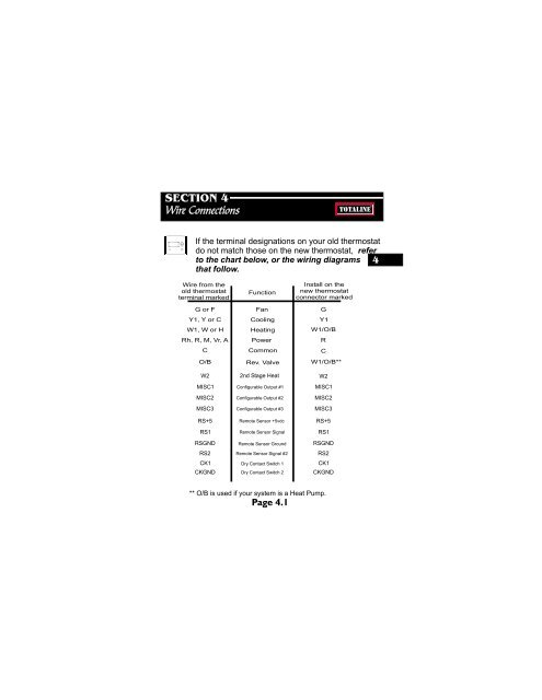
SECTION 4Wire ConnectionsTOTALINEIf the terminal designations on your old thermostatdo not match those on the new thermostat, referto the chart below, or the wiring diagrams 4that follow.Wire from theold thermostatterminal markedFunction<strong>Install</strong> on thenew thermostatconnector markedG or F Fan GY1, Y or C Cooling Y1W1, W or H Heating W1/O/BRh, R, M, Vr, A PowerRCO/BCommon<strong>Rev</strong>. ValveCW1/O/B**W2MISC1MISC2MISC32nd Stage HeatConfigurable Output #1Configurable Output #2Configurable Output #3W2MISC1MISC2MISC3RS+5 Remote Sensor +5vdcRS+5RS1Remote Sensor SignalRS1RSGND Remote Sensor Ground RSGNDRS2Remote Sensor Signal #2RS2CK1 Dry Contact Switch 1 CK1CKGND Dry Contact Switch 2CKGND** O/B is used if your system is a Heat Pump.Page 4.1