SIMOVERT MASTERDRIVES Vector Control - Industry
SIMOVERT MASTERDRIVES Vector Control - Industry
SIMOVERT MASTERDRIVES Vector Control - Industry

Create successful ePaper yourself
Turn your PDF publications into a flip-book with our unique Google optimized e-Paper software.
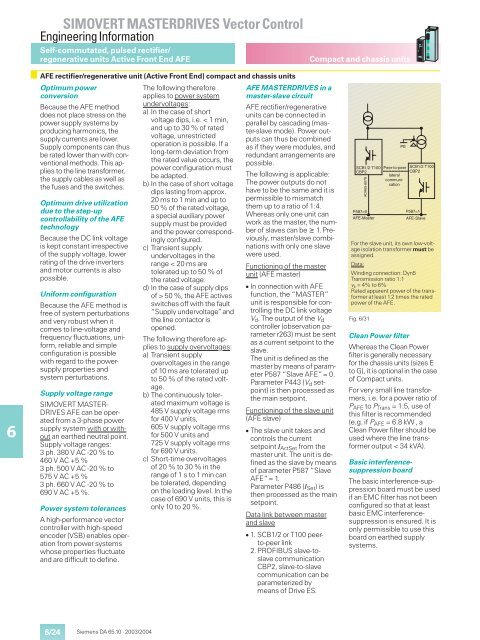
<strong>SIMOVERT</strong> <strong>MASTERDRIVES</strong> <strong>Vector</strong> <strong>Control</strong>Engineering InformationSelf-commutated, pulsed rectifier/regenerative units Active Front End AFECompact and chassis units6AFE rectifier/regenerative unit (Active Front End) compact and chassis unitsOptimum powerconversionBecause the AFE methoddoes not place stress on thepower supply systems byproducing harmonics, thesupply currents are lower.Supply components can thusbe rated lower than with conventionalmethods. This appliesto the line transformer,the supply cables as well asthe fuses and the switches.Optimum drive utilizationdue to the step-upcontrollability of the AFEtechnologyBecause the DC link voltageis kept constant irrespectiveof the supply voltage, lowerrating of the drive invertersand motor currents is alsopossible.Uniform configurationBecause the AFE method isfree of system perturbationsand very robust when itcomes to line-voltage andfrequency fluctuations, uniform,reliable and simpleconfiguration is possiblewith regard to the powersupplyproperties andsystem perturbations.Supply voltage range<strong>SIMOVERT</strong> MASTER-DRIVES AFE can be operatedfrom a 3-phase powersupply system with or withoutan earthed neutral point.Supply voltage ranges:3ph.380VAC-20%to460VAC+5%3ph.500VAC-20%to575VAC+5%3ph.660VAC-20%to690VAC+5%.Power system tolerancesA high-performance vectorcontroller with high-speedencoder (VSB) enables operationfrom power systemswhose properties fluctuateand are difficult to define.The following thereforeapplies to power systemundervoltages:a) In the case of shortvoltage dips, i.e. < 1 min,and up to 30 % of ratedvoltage, unrestrictedoperation is possible. If along-term deviation fromthe rated value occurs, thepower configuration mustbe adapted.b) In the case of short voltagedips lasting from approx.20 ms to 1 min and up to50 % of the rated voltage,a special auxiliary powersupply must be providedand the power correspondinglyconfigured.c) Transient supplyundervoltages in therange 50 %, the AFE activesswitches off with the fault“Supply undervoltage”andthe line contactor isopened.The following therefore appliesto supply overvoltages:a) Transient supplyovervoltages in the rangeof 10 ms are tolerated upto 50 % of the rated voltage.b) The continuously toleratedmaximum voltage is485 V supply voltage rmsfor 400 V units,605 V supply voltage rmsfor 500 V units and725 V supply voltage rmsfor 690 V units.c) Short-time overvoltagesof20%to30%intherange of1sto1mincanbe tolerated, dependingon the loading level. In thecase of 690 V units, this isonly 10 to 20 %.AFE <strong>MASTERDRIVES</strong> in amaster-slave circuitAFE rectifier/regenerativeunits can be connected inparallel by cascading (master-slavemode). Power outputscan thus be combinedas if they were modules, andredundant arrangements arepossible.The following is applicable:The power outputs do nothave to be the same and it ispermissible to mismatchthem up to a ratio of 1:4.Whereas only one unit canwork as the master, the numberof slaves can be 1. Previously,master/slave combinationswith only one slavewere used.Functioning of the masterunit (AFE master) In connection with AFEfunction, the “MASTER”unit is responsible for controllingthe DC link voltageV d . The output of the V dcontroller (observation parameterr263) must be sentas a current setpoint to theslave.The unit is defined as themaster by means of parameterP587 “Slave AFE“= 0.Parameter P443 (V d setpoint)is then processed asthe main setpoint.Functioning of the slave unit(AFE slave) The slave unit takes andcontrols the currentsetpoint I ActSet from themaster unit. The unit is definedas the slave by meansof parameter P587 “SlaveAFE“= 1.Parameter P486 (I Set )isthen processed as the mainsetpoint.Data link between masterand slave 1. SCB1/2 or T100 peerto-peerlink2.PROFIBUS slave-toslavecommunicationCBP2, slave-to-slavecommunication can beparameterized bymeans of Drive ES.For the slave unit, its own low-voltageisolation transformer must beassigned.Data:Winding connection: Dyn5Transmission ratio 1:1v k =4%to6%Rated apparent power of the transformerat least 1.2 times the ratedpower of the AFE.Fig. 6/31PESCB1/2 T100 Peer-to-peerCBP2lateralcommunicationDA65-6079AP587=0AFE-MasterSCB1/2 T100CBP2P587=1AFE-SlaveClean Power filterWhereas the Clean Powerfilter is generally necessaryfor the chassis units (sizes Eto G), it is optional in the caseof Compact units.For very small line transformers,i.e. for a power ratio ofP AFE to P Trans = 1:5, use ofthis filter is recommended(e.g. if P AFE = 6.8 kW , aClean Power filter should beused where the line transformeroutput < 34 kVA).Basic interferencesuppressionboardThe basic interference-suppressionboard must be usedif an EMC filter has not beenconfigured so that at leastbasic EMC interferencesuppressionis ensured. It isonly permissible to use thisboard on earthed supplysystems.6/24Siemens DA 65.10 · 2003/2004