SIMOVERT MASTERDRIVES Vector Control - Industry
SIMOVERT MASTERDRIVES Vector Control - Industry
SIMOVERT MASTERDRIVES Vector Control - Industry

You also want an ePaper? Increase the reach of your titles
YUMPU automatically turns print PDFs into web optimized ePapers that Google loves.
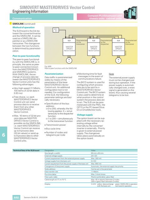
<strong>SIMOVERT</strong> <strong>MASTERDRIVES</strong> <strong>Vector</strong> <strong>Control</strong>Engineering InformationCommunicationCompact PLUS/compact andchassis units · cabinet units6SIMOLINK (continued)Method of operationThe SLB board is the link betweenthe converter/inverterand the SIMOLINK. It can beused as a SIMOLINK dispatcheror as a SIMOLINKtransceiver. The changeoverbetween the two functionsis determined by parameterization.Peer-to-peer functionalityThe peer-to-peer functionalitywith the SIMOLINK is, inprinciple, the same as peerto-peerconnection knownfrom the <strong>MASTERDRIVES</strong>and SIMOREG systems.With SIMOLINK, the exchangeof process data betweenthe <strong>MASTERDRIVES</strong><strong>Vector</strong> <strong>Control</strong> units has thefollowing advantages: Very high speed (11 Mbit/s;100 items of 32-bit data in0.63 ms) Free choice, i.e. each<strong>MASTERDRIVES</strong> <strong>Vector</strong><strong>Control</strong> unit can sendprocess data to or receivethem from any other<strong>MASTERDRIVES</strong><strong>Vector</strong> <strong>Control</strong>. Max. 16 items of 32-bit processdata per MASTER-DRIVES <strong>Vector</strong> <strong>Control</strong> ispossible via the SIMOLINK;i.e. each <strong>MASTERDRIVES</strong><strong>Vector</strong> <strong>Control</strong> can receiveup to 8 process data(32-bit values) or send upto 8 process data to other<strong>MASTERDRIVES</strong> <strong>Vector</strong><strong>Control</strong> units.Fig. 6/69Peer-to-peer functions with the SIMOLINKParameterization Parameterized Parameterized as theas thetransceiverdispatcher<strong>MASTERDRIVES</strong><strong>Vector</strong> <strong>Control</strong>Data traffic is parameterizedsolely by means of theparameters of the base<strong>MASTERDRIVES</strong> <strong>Vector</strong><strong>Control</strong> unit. An additionalconfiguration tool is notneeded. For configurationof the SLB, the followingparameter settings are basicallynecessary: Specification of the busaddress:@ 0 to 200, whereby the followingapplies: 0 = simultaneouslyto the dispatcherfunction@ 1 to 200 = simultaneouslyto the transceiver function Transmission power Bus cycle time Number of nodes andtelegrams per node<strong>MASTERDRIVES</strong><strong>Vector</strong> <strong>Control</strong> Monitoring time for faultmessages in the event ofcommunications failure.The BICO system is used forconfiguring which processdata are to be sent by a<strong>MASTERDRIVES</strong> <strong>Vector</strong><strong>Control</strong> unit. The BICO systemis also used to determine atwhat position in the controlsystem the process data areto act. The SLB can be parameterizedwith the PMU, theOP1S or the PC-based DriveES or DriveMonitor tools.Voltage supplyThe option board can be suppliedwith the necessary operatingvoltage eitherinternally by the converter/inverter or externally. Priorityis given to external powersupply. The changeovertakes place automatically onthe option board.<strong>MASTERDRIVES</strong><strong>Vector</strong> <strong>Control</strong>Parameterizedas thetransceiverNoteThe external power supplymust not be changed overduring bus operation. If thepower supply is automaticallychanged over, a resetsignal is generated on theboard, thus causing severaltelegrams to be lost.Technical Data of the SLB boardDesignationSize (length x width)External voltage supplyCurrent requirement from the external power supplyVoltage supply from the basic unitCurrent requirement from the power supply of the base unitChangeover of the power supplyNode addressData transfer rateRun-time delayFiber-optic cableValue90 mm x 83 mm24 V DCMax. 200 mA5 V DCMax. 600 mAAutomatic; the external supply has priorityCan be set in the parameter11 Mbit/sMax. 3 clock timesPlastic (preferable); glass fiberCable length at 0 °C to 70 °CMax. 40 m (plastic) between 2 nodes300 m (glass fiber) between 2 nodesDisplay 3 LED: yellow: data exchange green: SIMOLINK in operationwith the basic unit red: board in operation6/62Siemens DA 65.10 · 2003/2004