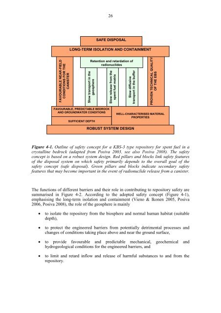
254 LONG-TERM SAFETY RELATED REQUIREMENTS ON HOST ROCKThe definition of per<strong>for</strong>mance targets is realised from a long-term safety point of view.Parallel design-related requirements are discussed in Chapter 6. The starting points indefining host rock per<strong>for</strong>mance targets are safety functions of the host rock <strong>and</strong>requirements arising from the per<strong>for</strong>mance targets set <strong>for</strong> the engineered barriers. Whendefining the per<strong>for</strong>mance targets <strong>for</strong> the host rock, it is necessary to take into accountsite evolution, possible detrimental impacts on safety due to disturbances caused byexcavation <strong>and</strong> operation (including the introduction of <strong>for</strong>eign materials, such ascement <strong>and</strong> metal structures) <strong>and</strong> finally the host rock properties affecting transport. Inaddition, properties considered to be favourable, though not required, <strong>for</strong> long-termsafety are mentioned.4.1 Safety concept <strong>and</strong> safety functions<strong>Posiva</strong>'s concept of spent fuel disposal is based on the KBS-3 design of a geologicrepository <strong>and</strong> the characteristics of Olkiluoto site (see e.g. <strong>Posiva</strong> 2008). <strong>Posiva</strong>’ssafety concept is illustrated in Figure 4-1. According to this concept, safety rests first<strong>and</strong> <strong>for</strong>emost on the long-term isolation <strong>and</strong> containment of radionuclides within thecopper-iron canisters. A clay buffer protects the canisters from rock movements <strong>and</strong>potential detrimental substances, limits groundwater flow around the canisters, alsolimiting <strong>and</strong> retarding radionuclide releases in the event of canister failure. Long-termcontainment within the canisters in turn depends primarily on proven technical qualityof the engineered barrier system (EBS) <strong>and</strong> favourable near-field conditions <strong>for</strong> thecanisters. The technical quality of the EBS is favoured by the use of components withwell-characterised material properties <strong>and</strong> by the development of appropriateacceptance specifications <strong>and</strong> design criteria. Favourable <strong>and</strong> predictable bedrock <strong>and</strong>groundwater conditions are requirements <strong>for</strong> selecting a waste disposal site.The EBS includes the canisters <strong>and</strong> a surrounding clay buffer that protects the canistersfrom rock movements <strong>and</strong> from potential detrimental substances in the groundwater.The EBS also includes other components, such as the backfill of the deposition tunnelas well as the backfill, plugs <strong>and</strong> seals of other cavities (central tunnels, shafts, accesstunnel, research boreholes). These are designed to be compatible with, <strong>and</strong> support thesafety functions of, the canister, the buffer <strong>and</strong> the host rock. For example, backfilling<strong>and</strong> sealing of the repository cavities (including tunnels, shafts <strong>and</strong> boreholes) supportthe safety functions of the host rock by giving mechanical support to the rock <strong>and</strong>preventing the <strong>for</strong>mation of transport pathways (water conductive flow paths). Theycontribute also to discourage inadvertent human intrusion into the repository. Thesurface environment does not have any barrier role <strong>and</strong> is thus not assigned any safetyfunctions or targets.Besides providing a protective environment <strong>for</strong> the canisters, situation <strong>and</strong> design of thedisposal system ensure that the transport of radionuclides released from an initiallydefective or subsequently failed canister will be effectively retained <strong>and</strong> retarded byother barriers. These are illustrated by the secondary set of safety pillars in Figure 4-1,spanning slow release from the spent fuel matrix, slow diffusive transport in thebuffer, <strong>and</strong> slow radionuclide transport in the geosphere.
FAVOURABLE NEAR-FIELDCONDITIONS FOR THECANISTERSlow transport in thegeosphereSlow release from thespent fuel matrixSlow diffusivetransport in the bufferPROVEN TECHNICAL QUALITYOF THE EBS26SAFE DISPOSALLONG-TERM ISOLATION AND CONTAINMENTRetention <strong>and</strong> retardation ofradionuclidesFAVOURABLE, PREDICTABLE BEDROCKAND GROUNDWATER CONDITIONSSUFFICIENT DEPTHWELL-CHARACTERISED MATERIALPROPERTIESROBUST SYSTEM DESIGNOutline of safety concept <strong>for</strong> a KBS-3 type repository <strong>for</strong> spent fuel in acrystalline bedrock (adapted from <strong>Posiva</strong> 2003). The safetyconcept is based on a robust system design. Red pillars <strong>and</strong> blocks link safety featuresof the disposal system on which safety primarily depends to the overall goal of thesafety concept (safe disposal). Green pillars <strong>and</strong> blocks indicate secondary safetyfeatures that may become important in the event of radionuclide release from a canister.The functions of different barriers <strong>and</strong> their role in contributing to repository safety aresummarised in Figure 4-2. According to the adopted safety concept (Figure 4-1),emphasising the long-term isolation <strong>and</strong> containment (Vieno & Ikonen 2005, <strong>Posiva</strong>2006, <strong>Posiva</strong> 2008), the role of the geosphere is mainlyto isolate the repository from the biosphere <strong>and</strong> normal human habitat (suitabledepth),to protect the engineered barriers from potentially detrimental processes <strong>and</strong>changes of conditions taking place above <strong>and</strong> near the ground surface,to provide favourable <strong>and</strong> predictable mechanical, geochemical <strong>and</strong>hydrogeological conditions <strong>for</strong> the engineered barriers, <strong>and</strong>to limit <strong>and</strong> retard inflow <strong>and</strong> release of harmful substances to <strong>and</strong> from therepository.
- Page 1 and 2: Working Report 2009-29RSC-Programme
- Page 3 and 4: ABSTRACTPosiva Oy, jointly owned by
- Page 5 and 6: PREFACEThis report presents the out
- Page 7 and 8: 26 ENGINEERING TARGETS ON HOST ROCK
- Page 9 and 10: 4Reference DesignThe discussion in
- Page 11 and 12: 6approach is presented in (Chapter
- Page 13 and 14: 8shall be estimable and be consider
- Page 15 and 16: 10ScaleParametersRepository scaleLa
- Page 17 and 18: 12Pilot hole dataThe logging of pil
- Page 19 and 20: 14determined on the basis of hydrau
- Page 21 and 22: 16understanding of site hydrogeolog
- Page 23 and 24: 18ensured to have by design at the
- Page 25 and 26: 20SafetyconceptSiteReferenceDesignT
- Page 27 and 28: 22Safety functionsPerformancetarget
- Page 32 and 33: 27The above are referred to as the
- Page 34 and 35: 29A summary of safety function indi
- Page 36 and 37: 31The results by Börgesson and Her
- Page 38 and 39: 33Performance target Target value R
- Page 40 and 41: 35Even this inflow would need to co
- Page 42 and 43: 37form a continuous path along the
- Page 44 and 45: 39Performance targets related to ch
- Page 46 and 47: 415 DEVELOPMENT OF THE ROCK SUITABI
- Page 48 and 49: 43The objectives and the scope of t
- Page 50 and 51: 45not only should high transmissive
- Page 52 and 53: 47next stage of the project, though
- Page 54 and 55: cumulative percent49100908070Tsum0-
- Page 56 and 57: 51Based on the reasoning above, the
- Page 58 and 59: 53averagely fractured rock are avoi
- Page 60 and 61: 55The utilised borehole data consis
- Page 62 and 63: 575.2.4 ResultsLayout determining f
- Page 64 and 65: 59The brittle deformation zones BFZ
- Page 66 and 67: 61In the future, after increased in
- Page 68 and 69: 63Widths of the deterministic influ
- Page 70 and 71: 65Determining the influence zone of
- Page 73: 68Respect distance volumeFault pair
- Page 78 and 79: 735.2.5 Uncertainties in layout det
- Page 80 and 81:
75Hydrogeological propertiesPerform
- Page 82 and 83:
77Performance target: Limited conce
- Page 84 and 85:
79any influence on the behaviour of
- Page 86 and 87:
81~ 350 m30252425262320FPIs/100 m15
- Page 88 and 89:
83In the post-closure and glacial p
- Page 90 and 91:
85the cores of the zones, the T-val
- Page 92 and 93:
87example, 100 metres would have an
- Page 94 and 95:
89proposed criteria and to the eval
- Page 96 and 97:
91needed in order to assess effects
- Page 98 and 99:
93The classification process and th
- Page 100:
95was based on the latest DFN descr
- Page 103 and 104:
98described above. After a discussi
- Page 105 and 106:
100and shafts can pass through (as
- Page 107 and 108:
102orientation in terms of principa
- Page 109 and 110:
104influence zone of the structure.
- Page 111 and 112:
106Requirement in the E.5 (Draft 3)
- Page 113 and 114:
108be carried out at repository lev
- Page 115 and 116:
110hydraulical importance that shou
- Page 117 and 118:
112
- Page 119 and 120:
114Degueldre, C., Triay, I., Kim, J
- Page 121 and 122:
116Milnes, A.G., Aaltonen, I., Kemp
- Page 123:
118STUK. 2001. Long-Term Safety of