
Create successful ePaper yourself
Turn your PDF publications into a flip-book with our unique Google optimized e-Paper software.
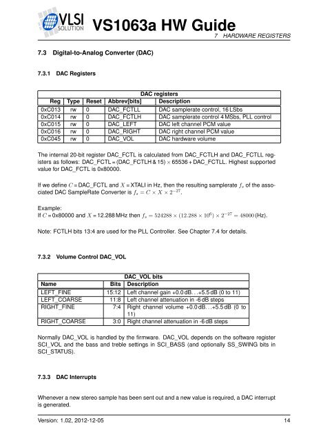
<strong>VS1063</strong>a HW <strong>Guide</strong>7 HARDWARE REGISTERS7.3 Digital-to-Analog Converter (DAC)7.3.1 DAC RegistersDAC registersReg Type Reset Abbrev[bits] Description0xC013 rw 0 DAC_FCTLL DAC samplerate control, 16 LSbs0xC014 rw 0 DAC_FCTLH DAC samplerate control 4 MSbs, PLL control0xC015 rw 0 DAC_LEFT DAC left channel PCM value0xC016 rw 0 DAC_RIGHT DAC right channel PCM value0xC045 rw 0 DAC_VOL DAC hardware volumeThe internal 20-bit register DAC_FCTL is calculated from DAC_FCTLH and DAC_FCTLL registersas follows: DAC_FCTL = (DAC_FCTLH & 15) × 65536 + DAC_FCTLL. Highest supportedvalue for DAC_FCTL is 0x80000.If we define C = DAC_FCTL and X = XTALI in Hz, then the resulting samplerate f s of the associatedDAC SampleRate Converter is f s = C × X × 2 −27 .Example:If C = 0x80000 and X = 12.288 MHz then f s = 524288 × (12.288 × 10 6 ) × 2 −27 = 48000 (Hz).Note: FCTLH bits 13:4 are used for the PLL Controller. See Chapter 7.4 for details.7.3.2 Volume Control DAC_VOLDAC_VOL bitsName Bits DescriptionLEFT_FINE 15:12 Left channel gain +0.0 dB. . .+5.5 dB (0 to 11)LEFT_COARSE 11:8 Left channel attenuation in -6 dB stepsRIGHT_FINE 7:4 Right channel volume +0.0 dB. . .+5.5 dB (0 to11)RIGHT_COARSE 3:0 Right channel attenuation in -6 dB stepsNormally DAC_VOL is handled by the firmware. DAC_VOL depends on the software registerSCI_VOL and the bass and treble settings in SCI_BASS (and optionally SS_SWING bits inSCI_STATUS).7.3.3 DAC InterruptsWhenever a new stereo sample has been sent out and a new value is required, a DAC interruptis generated.Version: 1.02, 2012-12-05 14