

Texture Sprayers Electrical & Mechinical Troubleshooting Manual
Texture Sprayers Electrical & Mechinical Troubleshooting Manual
Texture Sprayers Electrical & Mechinical Troubleshooting Manual

Create successful ePaper yourself
Turn your PDF publications into a flip-book with our unique Google optimized e-Paper software.
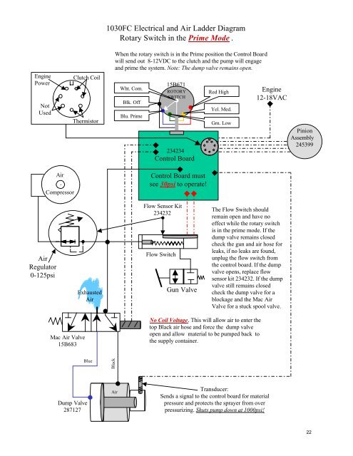
EnginePowerNotUsedClutch CoilThermistor1030FC <strong>Electrical</strong> and Air Ladder DiagramRotary Switch in the Prime Mode .When the rotary switch is in the Prime position the Control Boardwill send out 8-12VDC to the clutch and the pump will engageand prime the system. Note: The dump valve remains open.Wht. Com.Blk. OffBlu. Prime15B671ROTORYSWITCH234234Control BoardRed HighYel. Med.Grn. LowEngine12-18VACPinionAssembly245399AirCompressorControl Board mustsee 30psi to operate!AirRegulator0-125psiExhaustedAirFlow Sensor Kit234232Flow SwitchGun ValveThe Flow Switch shouldremain open and have noeffect while the rotary switchis in the prime mode. If thedump valve remains closedcheck the gun and air hose forleaks, if no leaks are found,unplug the flow switch fromthe control board. If the dumpvalve opens, replace flowsensor kit 234232. If the dumpvalve still remains closedcheck the dump valve for ablockage and the Mac AirValve for a stuck spool valve.Mac Air Valve15B683No Coil Voltage. This will allow air to enter thetop Black air hose and force the dump valveopen and allow material to be pumped back tothe supply container.BlueBlackDump Valve287127AirTransducer:Sends a signal to the control board for materialpressure and protects the sprayer from overpressurizing. Shuts pump down at 1000psi!22


