

309029D Automatic Delta Spray Air Spray Gun ... - Graco Inc.
309029D Automatic Delta Spray Air Spray Gun ... - Graco Inc.
309029D Automatic Delta Spray Air Spray Gun ... - Graco Inc.

Create successful ePaper yourself
Turn your PDF publications into a flip-book with our unique Google optimized e-Paper software.
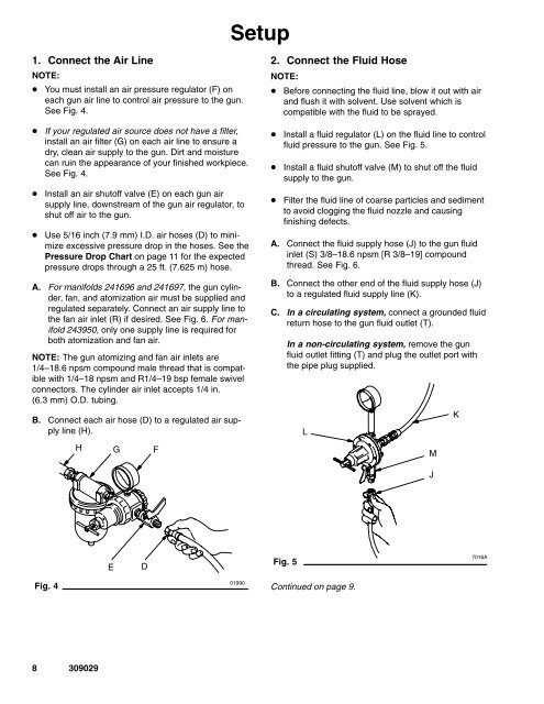
Setup1. Connect the <strong>Air</strong> LineNOTE: You must install an air pressure regulator (F) oneach gun air line to control air pressure to the gun.See Fig. 4.If your regulated air source does not have a filter,install an air filter (G) on each air line to ensure adry, clean air supply to the gun. Dirt and moisturecan ruin the appearance of your finished workpiece.See Fig. 4.Install an air shutoff valve (E) on each gun airsupply line, downstream of the gun air regulator, toshut off air to the gun.Use 5/16 inch (7.9 mm) I.D. air hoses (D) to minimizeexcessive pressure drop in the hoses. See thePressure Drop Chart on page 11 for the expectedpressure drops through a 25 ft. (7.625 m) hose.A. For manifolds 241696 and 241697, the gun cylinder,fan, and atomization air must be supplied andregulated separately. Connect an air supply line tothe fan air inlet (R) if desired. See Fig. 6. For manifold243950, only one supply line is required forboth atomization and fan air.NOTE: The gun atomizing and fan air inlets are1/4–18.6 npsm compound male thread that is compatiblewith 1/4–18 npsm and R1/4–19 bsp female swivelconnectors. The cylinder air inlet accepts 1/4 in.(6.3 mm) O.D. tubing.B. Connect each air hose (D) to a regulated air supplyline (H).HGF2. Connect the Fluid HoseNOTE: Before connecting the fluid line, blow it out with airand flush it with solvent. Use solvent which iscompatible with the fluid to be sprayed.Install a fluid regulator (L) on the fluid line to controlfluid pressure to the gun. See Fig. 5.Install a fluid shutoff valve (M) to shut off the fluidsupply to the gun.Filter the fluid line of coarse particles and sedimentto avoid clogging the fluid nozzle and causingfinishing defects.A. Connect the fluid supply hose (J) to the gun fluidinlet (S) 3/8–18.6 npsm [R 3/8–19] compoundthread. See Fig. 6.B. Connect the other end of the fluid supply hose (J)to a regulated fluid supply line (K).C. In a circulating system, connect a grounded fluidreturn hose to the gun fluid outlet (T).In a non-circulating system, remove the gunfluid outlet fitting (T) and plug the outlet port withthe pipe plug supplied.LMKJEDFig. 57016AFig. 401990Continued on page 9.8 309029


