

320386-001 - AO Smith Water Heaters
320386-001 - AO Smith Water Heaters
320386-001 - AO Smith Water Heaters

You also want an ePaper? Increase the reach of your titles
YUMPU automatically turns print PDFs into web optimized ePapers that Google loves.
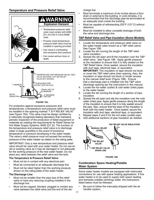
Temperature and Pressure Relief Valve1” MINIMUMMETALDRAIN PANDRAINExplosion Harzard• Temperature-pressure reliefvalve must comply with ANSIZ21.22-CSA 4.4 and ASMEcode.• Properly sized temperaturepressurerelief valve must beinstalled in opening provided.• Can result in overheatingand excessive tank pressure.• Can cause serious injury ordeath.TEMPERATURE AND PRESSURE RELIEF (T&P)VALVE (OPTIONAL TOP T&P RELIEFVALVE NOT SHOWN)DISCHARGE PIPEDO NOT CAP OR PLUGDRAIN LINE 3/4”ID MINIMUMFIGURE 15A.6” MAXIMUMAIR GAPFor protection against excessive pressures andtemperatures, a temperature and pressure relief valve mustbe installed in the opening marked “T & P RELIEF VALVE”(see Figure 15A). This valve must be design certified bya nationally recognized testing laboratory that maintainsperiodic inspection of the production of listed equipment ormaterials as meeting the requirements for Relief Valves forHot <strong>Water</strong> Supply Systems, ANSI Z21.22. The function ofthe temperature and pressure relief valve is to dischargewater in large quantities in the event of excessivetemperature or pressure developing in the water heater.The valve’s relief pressure must not exceed the workingpressure of the water heater as stated on the rating plate.IMPORTANT: Only a new temperature and pressure reliefvalve should be used with your water heater. Do not use anold or existing valve as it may be damaged or not adequatefor the working pressure of the new water heater. Do notplace any valve between the relief valve and the tank.The Temperature & Pressure Relief Valve:• Must not be in contact with any electrical part.• Must be connected to an adequate discharge line.• Must not be rated higher than the working pressureshown on the rating plate of the water heater.The Discharge Line:• Must not be smaller than the pipe size of the reliefvalve or have any reducing coupling installed in thedischarge line.• Must not be capped, blocked, plugged or contain anyvalve between the relief valve and the end of the dis-17charge line.• Must terminate a maximum of six inches above a floordrain or external to the building. In cold climates, it isrecommended that the discharge pipe be terminated atan adequate drain inside the building.• Must be capable of withstanding 250°F (121°C) withoutdistortion.• Must be installed to allow complete drainage of boththe valve and discharge line.T&P Relief Valve and Pipe Insulation (Some Models)1. Locate the temperature and pressure relief valve onthe water heater (also known as a T&P relief valve).See Figure 15B.2. Locate the slit running the length of the T&P reliefvalve insulation.3. Spread the slit open and fit the insulation over the T&Prelief valve. See Figure 15B. Apply gentle pressureto the insulation to ensure that it is fully seated on theT&P Relief Valve. Once seated, secure the insulationwith duct tape, electrical tape, or equivalent.IMPORTANT: The insulation or tape should not blockor cover the T&P relief valve drain opening. Also, theinsulation or tape should not block or hinder accessto the manual relief lever (Figure 15B). Ensurethat a discharge pipe is installed into the T&P valvedischarge opening per the instructions in this manual.4. Locate the hot water (outlet) & cold water (inlet) pipesto the water heater.5. Locate the slit running the length of a section of pipeinsulation.6. Spread the slit open and slip the insulation over the coldwater (inlet) pipe. Apply gentle pressure along the lengthof the insulation to ensure that it is fully seated aroundthe pipe. Also, ensure that the base of the insulation isflush with the water heater. Once seated, secure theinsulation with duct tape, electrical tape, or equivalent.7. Repeat steps 5 and 6 for the hot water (outlet) pipe.8. Add additional sections of pipe insulation as needed.MANUAL RELIEFLEVERT&P RELIEFVALVET&P RELIEF VALVEDRAIN LINET&P RELIEF VALVE INSULATIONFIGURE 15B.Combination Space Heating/Potable<strong>Water</strong> SystemSome water heater models are equipped with inlet/outletconnections for use with space heating applications. If thiswater heater is to be used to supply both space heatingand domestic potable (drinking) water, the instructionslisted below must be followed.• Be sure to follow the manual(s) shipped with the airhandler system.


