

320386-001 - AO Smith Water Heaters
320386-001 - AO Smith Water Heaters
320386-001 - AO Smith Water Heaters

You also want an ePaper? Increase the reach of your titles
YUMPU automatically turns print PDFs into web optimized ePapers that Google loves.
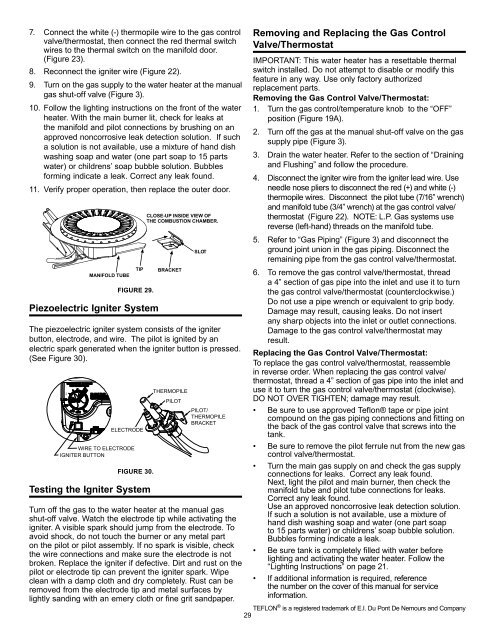
7. Connect the white (-) thermopile wire to the gas controlvalve/thermostat, then connect the red thermal switchwires to the thermal switch on the manifold door.(Figure 23).8. Reconnect the igniter wire (Figure 22).9. Turn on the gas supply to the water heater at the manualgas shut-off valve (Figure 3).10. Follow the lighting instructions on the front of the waterheater. With the main burner lit, check for leaks atthe manifold and pilot connections by brushing on anapproved noncorrosive leak detection solution. If sucha solution is not available, use a mixture of hand dishwashing soap and water (one part soap to 15 partswater) or childrens’ soap bubble solution. Bubblesforming indicate a leak. Correct any leak found.11. Verify proper operation, then replace the outer door.MANIFOLD TUBETIPFIGURE 29.Piezoelectric Igniter SystemCLOSE-UP INSIDE VIEW OFTHE COMBUSTION CHAMBER.BRACKETSLOTThe piezoelectric igniter system consists of the igniterbutton, electrode, and wire. The pilot is ignited by anelectric spark generated when the igniter button is pressed.(See Figure 30).VACELECTRODEWIRE TO ELECTRODEIGNITER BUTTONFIGURE 30.Testing the Igniter SystemTHERMOPILEPILOTPILOT/THERMOPILEBRACKETTurn off the gas to the water heater at the manual gasshut-off valve. Watch the electrode tip while activating theigniter. A visible spark should jump from the electrode. Toavoid shock, do not touch the burner or any metal parton the pilot or pilot assembly. If no spark is visible, checkthe wire connections and make sure the electrode is notbroken. Replace the igniter if defective. Dirt and rust on thepilot or electrode tip can prevent the igniter spark. Wipeclean with a damp cloth and dry completely. Rust can beremoved from the electrode tip and metal surfaces bylightly sanding with an emery cloth or fine grit sandpaper.Removing and Replacing the Gas ControlValve/ThermostatIMPORTANT: This water heater has a resettable thermalswitch installed. Do not attempt to disable or modify thisfeature in any way. Use only factory authorizedreplacement parts.Removing the Gas Control Valve/Thermostat:1. Turn the gas control/temperature knob to the “OFF”position (Figure 19A).2. Turn off the gas at the manual shut-off valve on the gassupply pipe (Figure 3).3. Drain the water heater. Refer to the section of “Drainingand Flushing” and follow the procedure.4. Disconnect the igniter wire from the igniter lead wire. Useneedle nose pliers to disconnect the red (+) and white (-)thermopile wires. Disconnect the pilot tube (7/16” wrench)and manifold tube (3/4” wrench) at the gas control valve/thermostat (Figure 22). NOTE: L.P. Gas systems usereverse (left-hand) threads on the manifold tube.5. Refer to “Gas Piping” (Figure 3) and disconnect theground joint union in the gas piping. Disconnect theremaining pipe from the gas control valve/thermostat.6. To remove the gas control valve/thermostat, threada 4” section of gas pipe into the inlet and use it to turnthe gas control valve/thermostat (counterclockwise.)Do not use a pipe wrench or equivalent to grip body.Damage may result, causing leaks. Do not insertany sharp objects into the inlet or outlet connections.Damage to the gas control valve/thermostat mayresult.Replacing the Gas Control Valve/Thermostat:To replace the gas control valve/thermostat, reassemblein reverse order. When replacing the gas control valve/thermostat, thread a 4” section of gas pipe into the inlet anduse it to turn the gas control valve/thermostat (clockwise).DO NOT OVER TIGHTEN; damage may result.• Be sure to use approved Teflon® tape or pipe jointcompound on the gas piping connections and fitting onthe back of the gas control valve that screws into thetank.• Be sure to remove the pilot ferrule nut from the new gascontrol valve/thermostat.• Turn the main gas supply on and check the gas supplyconnections for leaks. Correct any leak found.Next, light the pilot and main burner, then check themanifold tube and pilot tube connections for leaks.Correct any leak found.Use an approved noncorrosive leak detection solution.If such a solution is not available, use a mixture ofhand dish washing soap and water (one part soapto 15 parts water) or childrens’ soap bubble solution.Bubbles forming indicate a leak.• Be sure tank is completely filled with water beforelighting and activating the water heater. Follow the“Lighting Instructions” on page 21.• If additional information is required, referencethe number on the cover of this manual for serviceinformation.TEFLON ® is a registered trademark of E.I. Du Pont De Nemours and Company29


