

320386-001 - AO Smith Water Heaters
320386-001 - AO Smith Water Heaters
320386-001 - AO Smith Water Heaters

You also want an ePaper? Increase the reach of your titles
YUMPU automatically turns print PDFs into web optimized ePapers that Google loves.
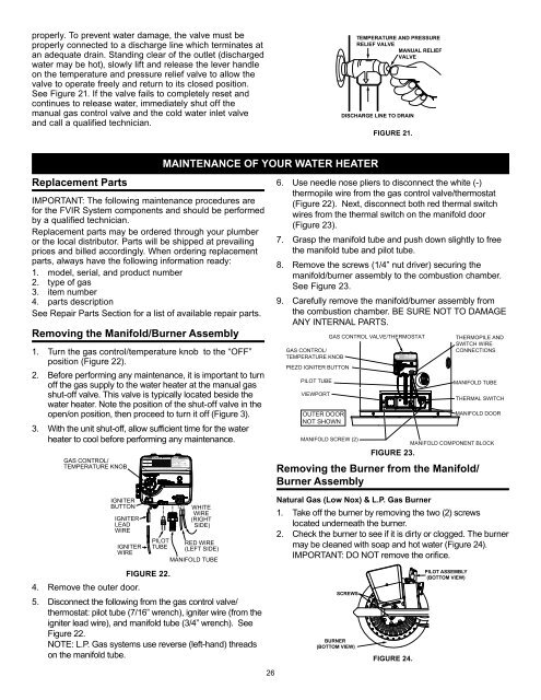
VACproperly. To prevent water damage, the valve must beproperly connected to a discharge line which terminates atan adequate drain. Standing clear of the outlet (dischargedwater may be hot), slowly lift and release the lever handleon the temperature and pressure relief valve to allow thevalve to operate freely and return to its closed position.See Figure 21. If the valve fails to completely reset andcontinues to release water, immediately shut off themanual gas control valve and the cold water inlet valveand call a qualified technician.TEMPERATURE AND PRESSURERELIEF VALVEMANUAL RELIEFVALVEDISCHARGE LINE TO DRAINFIGURE 21.Replacement PartsIMPORTANT: The following maintenance procedures arefor the FVIR System components and should be performedby a qualified technician.Replacement parts may be ordered through your plumberor the local distributor. Parts will be shipped at prevailingprices and billed accordingly. When ordering replacementparts, always have the following information ready:1. model, serial, and product number2. type of gas3. item number4. parts descriptionSee Repair Parts Section for a list of available repair parts.Removing the Manifold/Burner Assembly1. Turn the gas control/temperature knob to the “OFF”position (Figure 22).2. Before performing any maintenance, it is important to turnoff the gas supply to the water heater at the manual gasshut-off valve. This valve is typically located beside thewater heater. Note the position of the shut-off valve in theopen/on position, then proceed to turn it off (Figure 3).3. With the unit shut-off, allow sufficient time for the waterheater to cool before performing any maintenance.GAS CONTROL/TEMPERATURE KNOBIGNITERBUTTONIGNITERLEADWIREIGNITERWIREVACPILOTTUBEMAINTENANCE OF YOUR WATER HEATERWHITEWIRE(RIGHTSIDE)RED WIRE(LEFT SIDE)MANIFOLD TUBE6. Use needle nose pliers to disconnect the white (-)thermopile wire from the gas control valve/thermostat(Figure 22). Next, disconnect both red thermal switchwires from the thermal switch on the manifold door(Figure 23).7. Grasp the manifold tube and push down slightly to freethe manifold tube and pilot tube.8. Remove the screws (1/4” nut driver) securing themanifold/burner assembly to the combustion chamber.See Figure 23.9. Carefully remove the manifold/burner assembly fromthe combustion chamber. BE SURE NOT TO DAMAGEANY INTERNAL PARTS.GAS CONTROL/TEMPERATURE KNOBPIEZO IGNITER BUTTONPILOT TUBEVIEWPORTOUTER DOORNOT SHOWNGAS CONTROL VALVE/THERMOSTATMANIFOLD SCREW (2)FIGURE 23.THERMOPILE ANDSWITCH WIRECONNECTIONSMANIFOLD TUBETHERMAL SWITCHMANIFOLD DOORMANIFOLD COMPONENT BLOCKRemoving the Burner from the Manifold/Burner AssemblyNatural Gas (Low Nox) & L.P. Gas Burner1. Take off the burner by removing the two (2) screwslocated underneath the burner.2. Check the burner to see if it is dirty or clogged. The burnermay be cleaned with soap and hot water (Figure 24).IMPORTANT: DO NOT remove the orifice.FIGURE 22.4. Remove the outer door.5. Disconnect the following from the gas control valve/thermostat: pilot tube (7/16” wrench), igniter wire (from theigniter lead wire), and manifold tube (3/4” wrench). SeeFigure 22.NOTE: L.P. Gas systems use reverse (left-hand) threadson the manifold tube.SCREWSBURNER(BOTTOM VIEW)FIGURE 24.PILOT ASSEMBLY(BOTTOM VIEW)26


