

320386-001 - AO Smith Water Heaters
320386-001 - AO Smith Water Heaters
320386-001 - AO Smith Water Heaters

You also want an ePaper? Increase the reach of your titles
YUMPU automatically turns print PDFs into web optimized ePapers that Google loves.
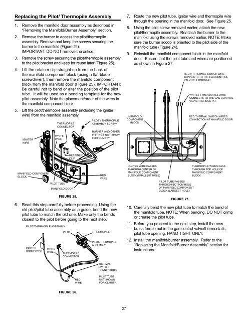
Replacing the Pilot/ Thermopile Assembly1. Remove the manifold door assembly as described in“Removing the Manifold/Burner Assembly” section.2. Remove the burner to access the pilot/thermopileassembly. Remove and keep the screws securing theburner to the manifold (Figure 24).IMPORTANT: DO NOT remove the orifice.3. Remove the screw securing the pilot/thermopile assemblyto the pilot bracket and keep for reuse later (Figure 25).4. Lift the retainer clip straight up from the back ofthe manifold component block (using a flat-bladescrewdriver), then remove the manifold componentblock from the manifold door (Figure 25). IMPORTANT:Be careful not to bend or alter the position of the pilottube. It will be used as a bending template for the newpilot assembly. Note the placement/order of the wires inthe manifold component block.5. Lift the pilot/thermopile assembly (including the igniterwire) from the manifold assembly.IGNITERWIRETHERMOPILECONNECTORWHITEWIREPILOT / THERMOPILEASSEMBLY SCREWBURNER AND OTHERFITTINGS NOT SHOWFOR CLARITY.7. Route the new pilot tube, igniter wire and thermopile wirethrough the opening in the manifold door. See Figure 25.8. Using the pilot screw removed earlier, attach the newpilot/thermopile assembly. Reattach the burner to themanifold using the screws removed earlier. NOTE: Makesure the burner scoop is oriented to the pilot side of themanifold tube (Figure 24).9. Reinstall the manifold component block in the manifolddoor. Ensure that the pilot tube and wires are positionedas shown in Figure 27.MANIFOLDCOMPONENTBLOCKRED (+) THERMAL SWITCH WIRECONNECTS TO THE GAS CONTROLVALVE\THERMOSTAT.WHITE (-) THERMOPILE WIRECONNECTS TO THE GAS CONTROLVALVE\THERMOSTAT.RED THERMAL SWITCH WIRESCONNECTION AT MANIFOLD DOORRETAINERCLIPMANIFOLD COMPONENTBLOCKPILOT TUBEMANIFOLD DOORFIGURE 25.REDWIRE6. Read this step carefully before proceeding. Using theold pilot/pilot tube assembly as a guide, bend the newpilot tube to match the old one. Make only the bendsclosest to the pilot before going to the next step.PILOT/THERMOPILE ASSEMBLYIGNITERCONNECTORWHITEWIREPILOTTHERMOPILECONNECTORTHERMOPILEPILOT/THERMOPILEASSEMBLYIGNITER WIRE PASSESTHROUGH CENTER OFMANIFOLD COMPONENTBLOCK (SMALLEST HOLE)PILOT TUBE PASSESTHROUGH BOTTOM HOLEOF MANIFOLD COMPONENTBLOCK (LARGEST HOLE)FIGURE 27.THERMOPILE WIRES PASSTHROUGH TOP HOLE OFMANIFOLD COMPONENTBLOCK10. Carefully bend the new pilot tube to match the bend ofthe manifold tube. NOTE: When bending, DO NOT crimpor crease the pilot tube.11. Before you proceed to the next step, install the newbrass ferrule nut in the gas control valve/thermostat’spilot tube opening, HAND TIGHT ONLY.12. Install the manifold/burner assembly. Refer to the“Replacing the Manifold/Burner Assembly” section forinstructions.THERMALSWITCHCONNECTORSREDWIREPILOT TUBENOT SHOWNFOR CLARITY.FIGURE 26.27


