

320386-001 - AO Smith Water Heaters
320386-001 - AO Smith Water Heaters
320386-001 - AO Smith Water Heaters

You also want an ePaper? Increase the reach of your titles
YUMPU automatically turns print PDFs into web optimized ePapers that Google loves.
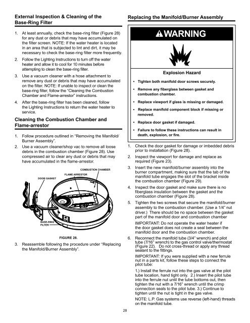
External Inspection & Cleaning of theBase-Ring Filter1. At least annually, check the base-ring filter (Figure 28)for any dust or debris that may have accumulated onthe filter screen. NOTE: If the water heater is locatedin an area that is subjected to lint and dirt, it may benecessary to check the base-ring filter more frequently.2. Follow the Lighting Instructions to turn off the waterheater and allow it to cool for 10 minutes beforeattempting to clean the base-ring filter.3. Use a vacuum cleaner with a hose attachment toremove any dust or debris that may have accumulatedon the filter. NOTE: If unable to inspect or clean thebase-ring filter, follow the “Cleaning the CombustionChamber and Flame-arrestor” instructions.4. After the base-ring filter has been cleaned, followthe Lighting Instructions to return the water heater toservice.Cleaning the Combustion Chamber andFlame-arrestor1. Follow procedure outlined in “Removing the Manifold/Burner Assembly”.2. Use a vacuum cleaner/shop vac to remove all loosedebris in the combustion chamber (Figure 28). Usecompressed air to clear any dust or debris that mayhave accumulated in the flame-arrestor.DOOR GASKETBASE-RINGFILTERFLAME ARRESTORCOMBUSTION CHAMBERFIGURE 28.3. Reassemble following the procedure under “Replacingthe Manifold/Burner Assembly”.28Replacing the Manifold/Burner AssemblyWARNINGExplosion Hazard• Tighten both manifold door screws securely.• Remove any fiberglass between gasket andcombustion chamber.• Replace viewport if glass is missing or damaged.• Replace manifold component block if missing orremoved.• Replace door gasket if damaged.• Failure to follow these instructions can result indeath, explosion, or fire.1. Check the door gasket for damage or imbedded debrisprior to installation (Figure 28).2. Inspect the viewport for damage and replace asrequired (Figure 23).3. Insert the new manifold/burner assembly into theburner compartment, making sure that the tab of themanifold tube engages the slot of the bracket insidethe combustion chamber (Figure 29).4. Inspect the door gasket and make sure there is nofiberglass insulation between the gasket and thecombustion chamber (Figure 28).5. Tighten the two screws that secure the manifold/burnerassembly to the combustion chamber. (Use a 1/4” nutdriver.) There should be no space between the gasketpart of the manifold door and combustion chamberIMPORTANT: Do not operate the water heater ifthe door gasket does not create a seal between themanifold door and the combustion chamber.6. Reconnect the manifold tube (3/4” wrench) and pilottube (7/16” wrench) to the gas control valve/thermostat(Figure 22). Do not cross-thread or apply any threadsealant to the fittings.IMPORTANT: If you were supplied with a new ferrulenut in a parts kit, follow these steps to connect thepilot tube:1.) Install the ferrule nut into the gas valve at the pilottube location, hand tight only. 2.) Insert the pilot tubeinto the ferrule nut until the tube bottoms out, thentighten the nut with a 7/16” wrench until the crimpconnection seals to the pilot tube. 3.) Continue totighten until the nut is tight in the gas valve.NOTE: L.P. Gas systems use reverse (left-hand) threadson the manifold tube.


