HEATING & AIR CONDITIONINGAny access hatches to the furnace are for authorized service personnel only, as there are no userserviceableparts on the furnace. Accordingly, do not attempt to tamper with the interior of the furnace.WarningBe cautious when washing the exterior of the motor home; water should never besprayed directly into the furnace vent. Should any water be forced beyond the rainbaffles into the furnace vent, the furnace may rust which, in turn, may cause impropercombustion and produce unwanted by-products of combustion.Before the beginning of each travel season, the furnace should be thoroughly cleaned and inspected. Anyobstructions, debris, or lint which may obstruct free air flow or impede the operation of the aircirculationsystem should be removed. For example, accumulated dust or lint could possibly obstruct theorifices for the pilot light or may accumulate on the blower blades and unbalance the operation of theblower. Additionally, any debris in the ductwork, when heated by the furnace, could emit unpleasantodors or possibly become a fire hazard.Consequently, the furnace system (including ductwork) should be periodically cleaned; annually isrecommended unless the motor home is subjected to dust levels significantly greater than average; inwhich case more frequent cleaning is recommended. The Owner’s Information Package providesrecommended cleaning tips and procedures; when needed, a more thorough cleaning should beperformed by a qualified service technician.Air Conditioning SystemThe factory-installed air-conditioning system is designed for 120 VAC power supplied either from theexternal power hookup cord or from the generator. Any unnecessary interior heat loading (e.g., exposureto direct sunlight for long periods of time; transmittance of sunlight through the windows) will work theair conditioning system harder and may compromise the desired results. Accordingly, if the airconditioning system is to be used, park the motor home in a shady location whenever possible and closedrapes on those windows exposed to direct sunlight. Additionally, any heat-producing sources (e.g.,oven, unnecessary lights) within the motor home will work against the air conditioning system; so striveto minimize their use.The air conditioning system is the major consumption device of electrical power in the motor home.When this system is being used in an RV park, cumulative use of these air-conditioning systems by theresident motor homes can create, at times, a bigger demand for electrical power than is actually available.Accordingly, at such times, a “brown-out” condition may arise—this is when the AC voltage normallyavailable drops to a lesser value (e.g., 10-20% below normal or more).“Brown-out” conditions cause appliances to draw greater currents to make up for the reduced voltage;thereby causing circuit breakers to trip or fuses to blow. Under such conditions, your own motor home3-3
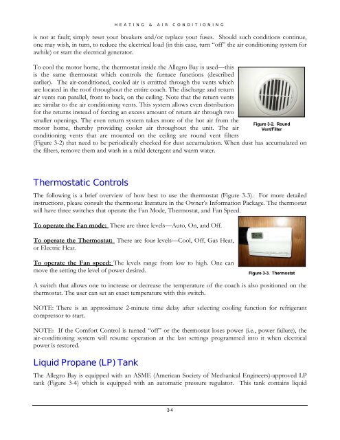
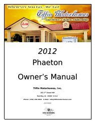
HEATING & AIR CONDITIONINGis not at fault; simply reset your breakers and/or replace your fuses. Should such conditions continue,one may wish, in turn, to reduce the electrical load (in this case, turn “off” the air conditioning system forawhile) or start the electrical generator.To cool the motor home, the thermostat inside the <strong>Allegro</strong> <strong>Bay</strong> is used—thisis the same thermostat which controls the furnace functions (describedearlier). The air-conditioned, cooled air is emitted through the vents whichare located in the roof throughout the entire coach. The discharge and returnair vents run parallel, front to back, on the ceiling. Note that the return ventsare similar to the air conditioning vents. This system allows even distributionfor the returns instead of forcing an excess amount of return air through twosmaller openings. The even return system takes more of the hot air from themotor home, thereby providing cooler air throughout the unit. The airconditioning vents that are mounted on the ceiling are round vent filtersFigure 3-2. RoundVent/Filter(Figure 3-2) that need to be periodically checked for dust accumulation. When dust has accumulated onthe filters, remove them and wash in a mild detergent and warm water.Thermostatic ControlsThe following is a brief overview of how best to use the thermostat (Figure 3-3). For more detailedinstructions, please consult the thermostat literature in the Owner’s Information Package. The thermostatwill have three switches that operate the Fan Mode, Thermostat, and Fan Speed.To operate the Fan mode: There are three levels—Auto, On, and Off.To operate the Thermostat: There are four levels—Cool, Off, Gas Heat,or Electric Heat.To operate the Fan speed: The levels range from low to high. One canmove the setting the level of power desired.Figure 3-3. ThermostatA switch that allows one to increase or decrease the temperature of the coach is also positioned on thethermostat. The user can set an exact temperature with this switch.NOTE: There is an approximate 2-minute time delay after selecting cooling function for refrigerantcompressor to start.NOTE: If the Comfort Control is turned “off” or the thermostat loses power (i.e., power failure), theair-conditioning system will resume operation at the last settings programmed into it when electricalpower is restored.Liquid Propane (LP) TankThe <strong>Allegro</strong> <strong>Bay</strong> is equipped with an ASME (American Society of Mechanical Engineers)-approved LPtank (Figure 3-4) which is equipped with an automatic pressure regulator. This tank contains liquid3-4
- Page 1 and 2: 2008Allegro BayOwner’s ManualTiff
- Page 3 and 4: ALLEGRO BAY OWNER’S MANUALTIFFIN
- Page 5: ALLEGRO BAY OWNER’S MANUALTelevis
- Page 8 and 9: GENERAL INFORMATIONChapter1GENERAL
- Page 10 and 11: GENERAL INFORMATION1. Read the warr
- Page 12 and 13: Owner’s Information PackageGENERA
- Page 14: GENERAL INFORMATIONWeighing Procedu
- Page 17 and 18: DRIVING & SAFETY INSTRUCTIONSSafety
- Page 19 and 20: DRIVING & SAFETY INSTRUCTIONS• Ch
- Page 21 and 22: DRIVING & SAFETY INSTRUCTIONSexcess
- Page 23 and 24: DRIVING & SAFETY INSTRUCTIONSmainta
- Page 25 and 26: DRIVING & SAFETY INSTRUCTIONSfurnac
- Page 28 and 29: HEATING & AIR CONDITIONINGChapter3H
- Page 32 and 33: HEATING & AIR CONDITIONINGpropane f
- Page 34: HEATING & AIR CONDITIONINGdetector
- Page 37 and 38: MAJOR APPLIANCES & ACCESSORIESRefri
- Page 39 and 40: MAJOR APPLIANCES & ACCESSORIESOn th
- Page 41 and 42: MAJOR APPLIANCES & ACCESSORIEStime
- Page 43 and 44: otating the antenna until optimal r
- Page 45 and 46: emote that comes with the televisio
- Page 47 and 48: MAJOR APPLIANCES & ACCESSORIES6. Ro
- Page 49 and 50: MAJOR APPLIANCES & ACCESSORIEStelep
- Page 51 and 52: Pressure-Relief ValveMAJOR APPLIANC
- Page 53 and 54: MAJOR APPLIANCES & ACCESSORIESWarni
- Page 55 and 56: MAJOR APPLIANCES & ACCESSORIESon th
- Page 58 and 59: CABINETS & FURNITUREChapter5Cabinet
- Page 60 and 61: CABINETS & FURNITUREIn the kitchen,
- Page 62 and 63: Bedroom AreaCABINETS & FURNITUREIf
- Page 64: CABINETS & FURNITURE5-7
- Page 67: STRUCTURAL FEATURESChassis Features
- Page 70 and 71: ELECTRICAL FEATURESGeneral Informat
- Page 72 and 73: ELECTRICAL FEATURESCautionDisconnec
- Page 74 and 75: typically, it is a break in the gro
- Page 76 and 77: ELECTRICAL FEATURES• Use the Gree
- Page 78 and 79: ELECTRICAL FEATURESWarningNever rep
- Page 81 and 82:
SLIDE-OUT FEATURESChapter8Slide-Out
- Page 83 and 84:
SLIDE-OUT FEATURESpower/water hooku
- Page 85:
SLIDE-OUT FEATURESNOTE: If the slid
- Page 88 and 89:
EXTERIOR FEATURESTowing HitchOn the
- Page 90 and 91:
EXTERIOR FEATURESthe leveling syste
- Page 92 and 93:
EXTERIOR FEATURESRETRACTION MODE:1.
- Page 94:
EXTERIOR FEATURESMirrorsThis motor
- Page 97 and 98:
INTERIOR FEATURESBedspreadAs a furn
- Page 100 and 101:
PLUMBING & BATH FEATURESChapter11Pl
- Page 102 and 103:
PLUMBING & BATH FEATURESspecified d
- Page 104 and 105:
PLUMBING & BATH FEATUREStank has be
- Page 106 and 107:
PLUMBING & BATH FEATURESpump still
- Page 108 and 109:
Black-Water Holding TankPLUMBING &
- Page 110 and 111:
PLUMBING & BATH FEATURESCautionThe
- Page 113 and 114:
CONSTRUCTION FEATURESChapter12Const
- Page 116 and 117:
WINDOWS, AWNINGS, VENTS, & DOORSCha
- Page 118 and 119:
WINDOWS, AWNINGS, VENTS, & DOORSmak
- Page 120 and 121:
WINDOWS, AWNINGS, VENTS, & DOORS7.
- Page 123 and 124:
ROUTINE MAINTENANCEChapter14Routine
- Page 125 and 126:
ROUTINE MAINTENANCEImportantNever u
- Page 127 and 128:
ROUTINE MAINTENANCEImportantDo not
- Page 129 and 130:
ROUTINE MAINTENANCEsettings, do not
- Page 131 and 132:
ROUTINE MAINTENANCE• When storing
- Page 133 and 134:
ROUTINE MAINTENANCEmentioned above,
- Page 135 and 136:
ROUTINE MAINTENANCEsidewall of the
- Page 137 and 138:
ROUTINE MAINTENANCEInformation on P
- Page 139 and 140:
ROUTINE MAINTENANCEAdditional Infor
- Page 141 and 142:
ROUTINE MAINTENANCEIt is the air pr
- Page 143 and 144:
ROUTINE MAINTENANCEExtra load tire
- Page 145 and 146:
ROUTINE MAINTENANCESidewall—That
- Page 147 and 148:
ROUTINE MAINTENANCEIf not stored un
- Page 149 and 150:
Frequency of Checking Tire Inflatio
- Page 151 and 152:
ROUTINE MAINTENANCETo start the vac
- Page 153 and 154:
ROUTINE MAINTENANCEDO NOT:• Use h
- Page 155 and 156:
ROUTINE MAINTENANCEMotorhomes Limit
- Page 157 and 158:
WinterizingROUTINE MAINTENANCETo st
- Page 159 and 160:
Dometic Refrigerator Ice Maker (opt
- Page 162 and 163:
MAINTENANCE & DATA CHARTSChapter15M
- Page 164 and 165:
MAINTENANCE & DATA CHARTSRV Owner
- Page 166 and 167:
MAINTENANCE & DATA CHARTSRV Owner
- Page 168 and 169:
MAINTENANCE & DATA CHARTSRV Owner
- Page 170 and 171:
MAINTENANCE & DATA CHARTSRV Owner