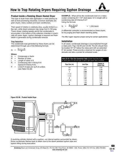
<strong>How</strong> <strong>to</strong> <strong>Trap</strong> Rotating Dryers Requiring Syphon DrainageProduct Inside a Rotating <strong>Steam</strong> Heated DryerThis type of dryer finds wide application in meat packing aswell as food processing industries. Common examples aregrain dryers, rotary cookers and bean conditioners.Their speed of rotation is relatively slow, usually limited <strong>to</strong> afew rpm, while steam pressure may range from 0-150 psig.These slower rotating speeds permit the condensate <strong>to</strong>accumulate in the bot<strong>to</strong>m of the collection chamber in practicallyall cases. Again, syphon drainage is required and flashsteam is generated during condensate removal.<strong>Trap</strong> SelectionThe condensate load generated by these dryers can bedetermined through use of the following formula:Q =N x L x RPWhere:Q = Condensate in lbs/hrN = Number of tubesL = Length of tubes in ftR = Condensing rate in lbs/sq ft-hr(typical 6-9 lbs/sq ft-hr)P = Lineal ft of pipe per sq ft of surface(see Table CG-26)EXAMPLE: What will be the condensate load on a rotarycooker containing 30 1-1/4" steel pipes 12' in length with acondensing rate of 8 lbs/sq ft-hr?Using the formula:30 x 12 x 8Q = = 1,252 lbs/hr2.30A differential controller is recommended on these dryersfor its purging and flash steam handling ability.The IBLV again requires proper sizing for certain applications.InstallationIn all cases, condensate drainage is accomplished througha rotary joint, Figs. CG-55 and CG-56. The DC should thenbe located 10"-12" below the rotary joint with an extended6" dirt pocket. These provide a reservoir for surges of condensateand also a pocket for entrained scale.Table CG-26. Pipe Size Conversion Table (Divide lineal feet of pipeby fac<strong>to</strong>r given for size and type of pipe <strong>to</strong> get square feet of surface)Pipe Size (in)Iron PipeCopper orBrass Pipe1/2 4.55 7.633/4 3.64 5.091 2.90 3.821-1/4 2.30 3.051-1/2 2.01 2.552 1.61 1.912-1/2 1.33 1.523 1.09 1.274 .848 .954Figure CG-56. Product Inside DryerRotaryJoint10''-12''DC6''A revolving cylinder drained with a syphon—an internal syphon surrounded by steam.Some condensate flashes back <strong>to</strong> steam due <strong>to</strong> the steam jacketed syphon pipe andsyphon lifting during evacuation.<strong>Armstrong</strong> <strong>Steam</strong> and Condensate Group, 816 Maple St., P.O. Box 408, Three Rivers, MI 49093 – USA Phone: (269) 273-1415 Fax: (269) 278-6555www.armstrong-intl.com45CG-40
<strong>How</strong> <strong>to</strong> <strong>Trap</strong> Flash TanksWhen hot condensate or boiler water, under pressure, isreleased <strong>to</strong> a lower pressure, part of it is re-evaporated,becoming what is known as flash steam. The heat conten<strong>to</strong>f flash is identical <strong>to</strong> that of live steam at the same pressure,although this valuable heat is wasted when allowed <strong>to</strong>escape through the vent in the receiver. With proper sizingand installation of a flash recovery system, the latent heatcontent of flash steam may be used for space heating;heating or preheating water, oil and other liquids; and lowpressure process heating.If exhaust steam is available it may be combined with theflash. In other cases, the flash will have <strong>to</strong> be supplementedby live make-up steam at reduced pressure. The actualamount of flash steam formed varies according <strong>to</strong> pressureconditions. The greater the difference between initial pressureand pressure on the discharge side, the greater theamount of flash that will be generated.To determine the exact amount, as a percentage, of flashsteam formed under certain conditions, refer <strong>to</strong> page CG-4for complete information.Refer <strong>to</strong> Chart CG-3 (page CG-4) for percentage of flash steamformed when discharging condensate <strong>to</strong> reduced pressure.A third type of device that may be the preferred selectionin many cases is the au<strong>to</strong>matic differential condensatecontroller. It combines the best features of both the IB andF&T and is recommended for large condensate loads thatexceed the separating capability of the flash tank.Safety Fac<strong>to</strong>rThe increased amount of condensate at start-up andthe varying loads during operation accompanied by lowpressure differential dictates a safety fac<strong>to</strong>r of 3:1 fortrapping flash tanks.Figure CG-57. Typical Flash Tank Piping SketchMake-upValve StrainerReducing Valve<strong>Trap</strong> SelectionThe condensate load can be calculated using the followingformula:Q = L -L x P100Where:Q = Condensate load in lbs/hr(<strong>to</strong> be handled by steam trap)L = Condensate flow in<strong>to</strong> flash tank in lbs/hrP = Percentage of flashEXAMPLE: Determine the condensate load of a flash tankwith 5,000 lbs/hr of 100 psig condensate entering the flashtank held at 10 psig. From page CG-4, the flash percentage isP = 10.5%. Using the formula:AlternateVentLocationRelief ValveFlash TankGaugeCVTo LowPressure<strong>Steam</strong> UseAir VentTo DrainHigh PressureCondensateReturn Line46CG-41Q = 5,000 - (5,000 x 10.5) = 4,475 lbs/hr100Due <strong>to</strong> the importance of energy conservation and operationagainst back pressure, the trap best suited for flash steamservice is the inverted bucket type with large bucket vent.In addition, the IB operates intermittently while venting airand CO 2 at steam temperature.In some cases, the float and thermostatic type trap is anacceptable alternative. One particular advantage of the F&Tis its ability <strong>to</strong> handle heavy start-up air loads.Chart CG-21. Recommendation Chart(See Page CG-2 for “Feature Code” References.)Equipment Being<strong>Trap</strong>pedFlash Tanks1st Choice andFeature CodeIBLVB, E, M, L, I, A, FAlternate ChoiceF&T or *DC*Recommended where condensate loads exceed the separating capability of theflash tank.IBLV <strong>Steam</strong> <strong>Trap</strong>To Low PressureCondensate ReturnFlash steam tank with live steam make-up, showingrecommended fittings and connections. The check valvesin the incoming lines prevent waste of flash when a line isnot in use. The by-pass is used when flash steam cannotbe used. Relief valves prevent pressure from building upand interfering with the operation of the high pressure steamtraps. The reducing valve reduces the high pressure steam<strong>to</strong> the same pressure as the flash, so they can be combinedfor process work or heating.<strong>Armstrong</strong> <strong>Steam</strong> and Condensate Group, 816 Maple St., P.O. Box 408, Three Rivers, MI 49093 – USA Phone: (269) 273-1415 Fax: (269) 278-6555www.armstrong-intl.com