How to Trap Steam Distribution Systems - Armstrong International, Inc.
How to Trap Steam Distribution Systems - Armstrong International, Inc.
How to Trap Steam Distribution Systems - Armstrong International, Inc.

Create successful ePaper yourself
Turn your PDF publications into a flip-book with our unique Google optimized e-Paper software.
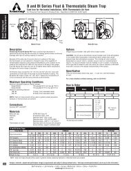
<strong>How</strong> <strong>to</strong> <strong>Trap</strong> Flash TanksInstallationCondensate return lines contain both flash steam and condensate.To recover the flash steam, the return header runs<strong>to</strong> a flash tank, where the condensate is drained, and steamis then piped from the flash tank <strong>to</strong> points of use, Fig. CG-57.Since a flash tank causes back pressure on the steam trapsdischarging in<strong>to</strong> the tank, these traps should be selected <strong>to</strong>ensure their capability <strong>to</strong> work against back pressure andhave sufficient capacity at the available differential pressures.Condensate lines should be pitched <strong>to</strong>ward the flash tank,and where more than one line feeds in<strong>to</strong> a flash tank, eachline should be fitted with a swing check valve. Then, any linenot in use will be isolated from the others and will not befed in reverse with resultant wasted flash steam. If the trap isoperating at low pressure, gravity drainage <strong>to</strong> the condensatereceiver should be provided.Generally, the location chosen for the flash tank shouldmeet the requirement for maximum quantity of flash steamand minimum length of pipe.Condensate lines, the flash tank, and the low pressuresteam lines should be insulated <strong>to</strong> prevent waste of flashthrough radiation. The fitting of a spray nozzle on the inletpipe inside the tank is not recommended. It may becomechoked, s<strong>to</strong>p the flow of condensate, and produce a backpressure <strong>to</strong> the traps.Low pressure equipment using flash steam should beindividually trapped and discharged <strong>to</strong> a low pressurereturn. Large volumes of air need <strong>to</strong> be vented from theflash tank; therefore, a thermostatic air vent should beused <strong>to</strong> remove the air and keep it from passing throughthe low pressure system.Figure CG-58. Flash <strong>Steam</strong> Recovery from an Air Heater BatteryFlash is taken from the flash tank and combined with livesteam, the pressure of which is reduced <strong>to</strong> that of the flashby a reducing valve.FlashTankLowPressureSectionHeaterBatteryHighPressure<strong>Steam</strong>AirFlowFlash Tank DimensionsThe flash tank can usually be conveniently constructed froma piece of large diameter piping with the bot<strong>to</strong>m ends weldedor bolted in position. The tank should be mounted vertically.A steam outlet is required at the <strong>to</strong>p and a condensateoutlet at the bot<strong>to</strong>m. The condensate inlet connection shouldbe 6''-8'' above the condensate outlet.The important dimension is the inside diameter. This shouldbe such that the upward velocity of flash <strong>to</strong> the outlet is lowenough <strong>to</strong> ensure that the amount of water carried overwith the flash is small. If the upward velocity is kept low, theheight of the tank is not important, but good practice is <strong>to</strong>use a height of 2'-3'.It has been found that a steam velocity of about 10' persecond inside the flash tank will give good separation ofsteam and water. On this basis, proper inside diametersfor various quantities of flash steam have been calculated;the results are plotted in Chart CG-22. This curve givesthe smallest recommended internal diameters. If it is moreconvenient, a larger tank may be used.Chart CG-22 does not take in<strong>to</strong> consideration pressure—onlyweight. Although volume of steam and upward velocity areless at a higher pressure, because steam is denser, there isan increased tendency for priming. Thus it is recommendedthat, regardless of pressure, Chart CG-22 be used <strong>to</strong> findthe internal diameter.Chart CG-22.Determination of Internal Diameter of Flash Tank<strong>to</strong> Handle a Given Quantity of Flash <strong>Steam</strong>Find amount of available flash steam (in pounds per hour)on bot<strong>to</strong>m scale, read up <strong>to</strong> curve and across <strong>to</strong> verticalscale, <strong>to</strong> get diameter in inches.INTERNAL DIAMETER OF FLASH TANK IN INCHES30252015105Condensate0 1,000 2,000 3,000 4,000 5,000 6,000POUNDS FLASH STEAM PER HOUR<strong>Armstrong</strong> <strong>Steam</strong> and Condensate Group, 816 Maple St., P.O. Box 408, Three Rivers, MI 49093 – USA Phone: (269) 273-1415 Fax: (269) 278-6555www.armstrong-intl.com47CG-42