How to Trap Steam Distribution Systems - Armstrong International, Inc.
How to Trap Steam Distribution Systems - Armstrong International, Inc.
How to Trap Steam Distribution Systems - Armstrong International, Inc.

Create successful ePaper yourself
Turn your PDF publications into a flip-book with our unique Google optimized e-Paper software.
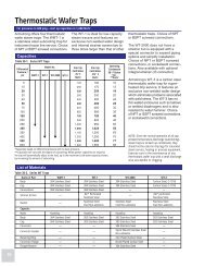
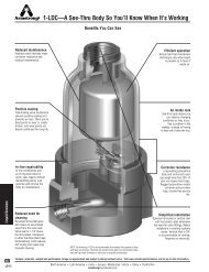
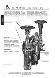
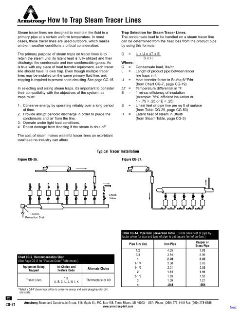
<strong>How</strong> <strong>to</strong> <strong>Trap</strong> <strong>Steam</strong> Tracer Lines<strong>Steam</strong> tracer lines are designed <strong>to</strong> maintain the fluid in aprimary pipe at a certain uniform temperature. In mostcases, these tracer lines are used outdoors, which makesambient weather conditions a critical consideration.The primary purpose of steam traps on tracer lines is <strong>to</strong>retain the steam until its latent heat is fully utilized and thendischarge the condensate and non-condensable gases. Asis true with any piece of heat transfer equipment, each tracerline should have its own trap. Even though multiple tracerlines may be installed on the same primary fluid line, unittrapping is required <strong>to</strong> prevent short circuiting. See page CG-15.In selecting and sizing steam traps, it’s important <strong>to</strong> considertheir compatibility with the objectives of the system, astraps must:1. Conserve energy by operating reliably over a long periodof time.2. Provide abrupt periodic discharge in order <strong>to</strong> purge thecondensate and air from the line.3. Operate under light load conditions.4. Resist damage from freezing if the steam is shut off.<strong>Trap</strong> Selection for <strong>Steam</strong> Tracer Lines.The condensate load <strong>to</strong> be handled on a steam tracer linecan be determined from the heat loss from the product pipeby using this formula:Q = L x U x ∆T x ES x HWhere:Q = Condensate load, lbs/hrL = Length of product pipe between tracerline traps in ftU = Heat transfer fac<strong>to</strong>r in Btu/sq ft/°F/hr(from Chart CG-7, page CG-19)∆T = Temperature differential in °FE = 1 minus efficiency of insulation(example: 75% efficient insulation or1 - .75 = .25 or E = .25)S = Lineal feet of pipe line per sq ft of surface(from Table CG-29, page CG-53)H = Latent heat of steam in Btu/lb(from <strong>Steam</strong> Table, page CG-3)The cost of steam makes wasteful tracer lines an exorbitan<strong>to</strong>verhead no industry can afford.Typical Tracer InstallationFigure CG-36.Figure CG-37.CheckValveFreeze-Protection Drain26CG-21Chart CG-9. Recommendation Chart(See Page CG-2 for “Feature Code” References.)Equipment Being<strong>Trap</strong>pedTracer Lines1st Choice andFeature Code*IBA, B, C, L, J, N, I, KAlternate ChoiceThermostatic or CD*Select a 5/64" steam trap orifice <strong>to</strong> conserve energy and avoid plugging with dirtand scale.Table CG-14. Pipe Size Conversion Table (Divide lineal feet of pipe byfac<strong>to</strong>r given for size and type of pipe <strong>to</strong> get square feet of surface.)Pipe Size (in)Iron PipeCopper orBrass Pipe1/2 4.55 7.633/4 3.64 5.091 2.90 3.821-1/4 2.30 3.051-1/2 2.01 2.552 1.61 1.912-1/2 1.33 1.523 1.09 1.274 .848 .954<strong>Armstrong</strong> <strong>Steam</strong> and Condensate Group, 816 Maple St., P.O. Box 408, Three Rivers, MI 49093 – USA Phone: (269) 273-1415 Fax: (269) 278-6555www.armstrong-intl.com