How to Trap Steam Distribution Systems - Armstrong International, Inc.
How to Trap Steam Distribution Systems - Armstrong International, Inc.
How to Trap Steam Distribution Systems - Armstrong International, Inc.

You also want an ePaper? Increase the reach of your titles
YUMPU automatically turns print PDFs into web optimized ePapers that Google loves.
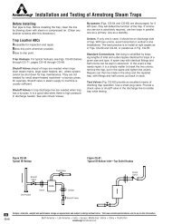
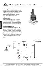
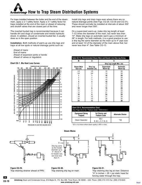
<strong>How</strong> <strong>to</strong> <strong>Trap</strong> <strong>Steam</strong> <strong>Distribution</strong> <strong>Systems</strong>For traps installed between the boiler and the end of the steammain, apply a 2:1 safety fac<strong>to</strong>r. Apply a 3:1 safety fac<strong>to</strong>r fortraps installed at the end of the main or ahead of reducingand shu<strong>to</strong>ff valves that are closed part of the time.The inverted bucket trap is recommended because it canhandle dirt and slugs of condensate and resists hydraulicshock. In addition, should an inverted bucket fail, it usuallydoes so in the open position.Installation. Both methods of warm-up use drip legs andtraps at all low spots or natural drainage points such as:Ahead of risersEnd of mainsAhead of expansion joints or bendsAhead of valves or regula<strong>to</strong>rsChart CG-7. Btu Heat Loss CurvesBTU PER SQ FT PER HOUR PER °F TEMPERATURE DIFFERENCETEMPERATURE DIFFERENCE150° 160° 180° 200° 240° 300° 400° 500° 700° 900° 1050°1110987654.54.03.53.33.02.82.62.52.42.32.22.15PSIG5.31"2"3"5"6"10"10.315.3FLAT SURFACES25.350.375.3100.3150.3250.3450.3600.3900.31500.32400.3PRESSURE IN LBS PER SQUARE INCH1110987654.54.03.53.33.02.82.62.52.42.32.22.152.10Install drip legs and drain traps even where there are nonatural drainage points (See Figs. CG-29, CG-30 and CG-31).These should normally be installed at intervals of about 300'and never longer than 500'.On a supervised warm-up, make drip leg length at least1-1/2 times the diameter of the main, but never less than10". Make drip legs on au<strong>to</strong>matic warm-ups a minimum of28" in length. For both methods, it is a good practice <strong>to</strong> usea drip leg the same diameter as the main up <strong>to</strong> 4" pipe sizeand at least 1/2 of the diameter of the main above that, butnever less than 4". See Table CG-13.Table CG-13. Recommended <strong>Steam</strong> Main and Branch Line Drip Leg SizingM<strong>Steam</strong> MainSize (in)Chart CG-8. Recommendation Chart(See Page CG-2 for “Feature Code” References.)Equipment Being<strong>Trap</strong>ped<strong>Steam</strong> Separa<strong>to</strong>r1st Choice andFeature CodeIBLVB, M, L, E, F, N, Q*DC is 1st choice where steam quality is 90% or less.DDrip LegDiameter (in)Drip Leg Length Min. (in)SupervisedWarm-UpAu<strong>to</strong>maticWarm-Up1/2 1/2 10 283/4 3/4 10 281 1 10 282 2 10 283 3 10 284 4 10 286 4 10 288 4 12 2810 6 15 2812 6 18 2814 8 21 2816 8 24 2818 10 27 2820 10 30 3024 12 36 36HAlternate Choice*DC<strong>Steam</strong> MainsMMDDrip leg sameas the headerdiameter up <strong>to</strong>4''. Above 4'',1/2 header size,but never lessthan 4''.HH24CG-19Figure CG-29.<strong>Trap</strong> draining strainer ahead of PRV.Figure CG-30.<strong>Trap</strong> draining drip leg on main.Figure CG-31.<strong>Trap</strong> draining drip leg at riser. Distance“H” in inches ÷ 28 = psi static head forforcing water through the trap.<strong>Armstrong</strong> <strong>Steam</strong> and Condensate Group, 816 Maple St., P.O. Box 408, Three Rivers, MI 49093 – USA Phone: (269) 273-1415 Fax: (269) 278-6555www.armstrong-intl.com