Flight and Operation Manual Rev 3.0 on 09-04-2013 - Trixy Aviation
Flight and Operation Manual Rev 3.0 on 09-04-2013 - Trixy Aviation
Flight and Operation Manual Rev 3.0 on 09-04-2013 - Trixy Aviation

Create successful ePaper yourself
Turn your PDF publications into a flip-book with our unique Google optimized e-Paper software.
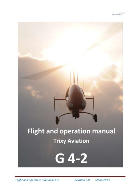
<str<strong>on</strong>g>Flight</str<strong>on</strong>g> <str<strong>on</strong>g>and</str<strong>on</strong>g> operati<strong>on</strong> manualfor Gyrocopter G 4-2Individual gyrocopter data here!This manual is to be carried al<strong>on</strong>g when operating the gyrocopter.The extent <str<strong>on</strong>g>and</str<strong>on</strong>g> state of revisi<strong>on</strong> of this manual may be obtained fromthe index <str<strong>on</strong>g>and</str<strong>on</strong>g> the revisi<strong>on</strong> index.The Gyrocopter G 4-2 may <strong>on</strong>ly be operated in accordance with theinstructi<strong>on</strong>s <str<strong>on</strong>g>and</str<strong>on</strong>g> within the operating limits included in this manual.This manual does not substitute a theoretical orpractical instructi<strong>on</strong> to operate this gyrocopter.<str<strong>on</strong>g>Rev</str<strong>on</strong>g>isi<strong>on</strong>: <str<strong>on</strong>g>3.0</str<strong>on</strong>g>Date issued: <strong>09</strong>.<strong>04</strong>.<strong>2013</strong><str<strong>on</strong>g>Flight</str<strong>on</strong>g> <str<strong>on</strong>g>and</str<strong>on</strong>g> operati<strong>on</strong> manual G 4-2 <str<strong>on</strong>g>Rev</str<strong>on</strong>g>isi<strong>on</strong> <str<strong>on</strong>g>3.0</str<strong>on</strong>g> – <strong>09</strong>.<strong>04</strong>.<strong>2013</strong> 2
REVISIONS TO THE FLIGHT OPERATIONS MANUALNo. Descripti<strong>on</strong> Page Date Signature<str<strong>on</strong>g>Flight</str<strong>on</strong>g> <str<strong>on</strong>g>and</str<strong>on</strong>g> operati<strong>on</strong> manual G 4-2 <str<strong>on</strong>g>Rev</str<strong>on</strong>g>isi<strong>on</strong> <str<strong>on</strong>g>3.0</str<strong>on</strong>g> – <strong>09</strong>.<strong>04</strong>.<strong>2013</strong> 3
INDEX1 GENERAL 81.1 Introducti<strong>on</strong> 81.2 Registrati<strong>on</strong> <str<strong>on</strong>g>and</str<strong>on</strong>g> certificati<strong>on</strong> basis 81.3 Performance data <str<strong>on</strong>g>and</str<strong>on</strong>g> operating procedure 81.4 Warnings <str<strong>on</strong>g>and</str<strong>on</strong>g> precauti<strong>on</strong>s 81.5 Three side views 121.6 Descripti<strong>on</strong> 141.7 Technical data 141.8 Rotor 141.9 Propeller 141.10 Power plant 151.11 Abbreviati<strong>on</strong>s <str<strong>on</strong>g>and</str<strong>on</strong>g> terminology 182 OPERATING LIMITS 202.1 Introducti<strong>on</strong> 202.2 <str<strong>on</strong>g>Flight</str<strong>on</strong>g> speeds 212.3 Engine limits 222.4 Weights 232.5 Center of gravity 242.6 Admissible maneuvers 242.7 G-forces 242.8 Minimum crew 242.9 Operating modes 242.10 Fuel 242.11 <str<strong>on</strong>g>Operati<strong>on</strong></str<strong>on</strong>g> fluids 252.12 Limitati<strong>on</strong> labels 263 NORMAL OPERATION 283.1 Introducti<strong>on</strong> 283.2 Periodic inspecti<strong>on</strong> 283.3 Pre-flight check 313.4 Pre-startup check 353.5 Operating procedures with external power source 353.6 Engine startup 353.7 Pre-taxi check 353.8 Check during taxying 353.9 Preparati<strong>on</strong> for take-off <str<strong>on</strong>g>and</str<strong>on</strong>g> pre rotati<strong>on</strong> 363.10 Take-off 37<str<strong>on</strong>g>Flight</str<strong>on</strong>g> <str<strong>on</strong>g>and</str<strong>on</strong>g> operati<strong>on</strong> manual G 4-2 <str<strong>on</strong>g>Rev</str<strong>on</strong>g>isi<strong>on</strong> <str<strong>on</strong>g>3.0</str<strong>on</strong>g> – <strong>09</strong>.<strong>04</strong>.<strong>2013</strong> 4
3.11 Climb 373.12 Cruise 373.13 Descent 373.14 Pre-l<str<strong>on</strong>g>and</str<strong>on</strong>g>ing check 383.15 Go-around procedure 383.16 Touchdown 383.17 Post l<str<strong>on</strong>g>and</str<strong>on</strong>g>ing check 393.18 Engine shut down 393.19 Securing the gyrocopter 393.20 Mounting <str<strong>on</strong>g>and</str<strong>on</strong>g> removing the rotor 403.21 H<str<strong>on</strong>g>and</str<strong>on</strong>g>ling the rotor system 403.22 Propeller 444 FLIGHT PERFORMANCE 464.1 Introducti<strong>on</strong> 464.2 Performance data 464.3 Influence through rain <str<strong>on</strong>g>and</str<strong>on</strong>g> insects 474.4 Max. ascertained cross-wind 474.5 Noise data 474.6 Tire pressure 474.7 Service ceiling 474.8 Torque specificati<strong>on</strong>s 484.9 Battery <str<strong>on</strong>g>and</str<strong>on</strong>g> generator 494.10 Altitude <str<strong>on</strong>g>and</str<strong>on</strong>g> pace diagram 495 WEIGHTS AND CENTER OF GRAVITY 505.1 Introducti<strong>on</strong> 505.2 Weighing procedure 515.3 Weighing report 525.4 Empty mass alterati<strong>on</strong> 535.5 Determining the center of gravitiy 556 SYSTEM DESCRIPTION 586.1 Introducti<strong>on</strong> 586.2 Gyrocopter explanati<strong>on</strong> 586.3 C<strong>on</strong>trol system 596.4 Instrument panel 626.5 Drive train 646.6 Seats <str<strong>on</strong>g>and</str<strong>on</strong>g> seat belts 646.7 Luggage compartments 65<str<strong>on</strong>g>Flight</str<strong>on</strong>g> <str<strong>on</strong>g>and</str<strong>on</strong>g> operati<strong>on</strong> manual G 4-2 <str<strong>on</strong>g>Rev</str<strong>on</strong>g>isi<strong>on</strong> <str<strong>on</strong>g>3.0</str<strong>on</strong>g> – <strong>09</strong>.<strong>04</strong>.<strong>2013</strong> 5
6.8 Doors, windows <str<strong>on</strong>g>and</str<strong>on</strong>g> exits 666.9 Fuel system 686.10 Electrical system 726.11 Dynamic <str<strong>on</strong>g>and</str<strong>on</strong>g> static pressure 727 GLASS COCKPIT 747.1 Introducti<strong>on</strong> 747.2 Explanati<strong>on</strong> 757.3 <str<strong>on</strong>g>Operati<strong>on</strong></str<strong>on</strong>g> 768 TRANSCEIVER, TRANSPONDER & ELT 868.1 Introducti<strong>on</strong> 868.2 Two-way-radio 868.3 Transp<strong>on</strong>der 868.4 ELT 869 POWER PLANT 889.1 Introducti<strong>on</strong> 889.2 Engine views 899.3 Engine legend 899.4 Oil system 9<strong>09</strong>.5 Cooling system 919.6 Igniti<strong>on</strong> system 919.7 Fuel system 929.8 Drivetrain maintenance 9210 PROPELLER 9411 HANDING, MAINTENANCE AND CARE 9611.1 Maintenance instructi<strong>on</strong>s 9611.2 Repairs 9811.3 Ground h<str<strong>on</strong>g>and</str<strong>on</strong>g>ling <str<strong>on</strong>g>and</str<strong>on</strong>g> road transport 9811.4 Maintenance <str<strong>on</strong>g>and</str<strong>on</strong>g> care operati<strong>on</strong>s 9911.5 Winter operati<strong>on</strong> 9911.6 <str<strong>on</strong>g>Operati<strong>on</strong></str<strong>on</strong>g> with closed cabin <str<strong>on</strong>g>and</str<strong>on</strong>g> cabin heat 10012 HANDBUCHERGÄNZUNGEN 10212.1 Introducti<strong>on</strong> 10212.2 Minimum equipment 10212.3 Opti<strong>on</strong>al auxiliary equipment 10312.4 List of installed opti<strong>on</strong>al equipment 10312.5 Reporting damages <str<strong>on</strong>g>and</str<strong>on</strong>g> accidents 1<strong>04</strong><str<strong>on</strong>g>Flight</str<strong>on</strong>g> <str<strong>on</strong>g>and</str<strong>on</strong>g> operati<strong>on</strong> manual G 4-2 <str<strong>on</strong>g>Rev</str<strong>on</strong>g>isi<strong>on</strong> <str<strong>on</strong>g>3.0</str<strong>on</strong>g> – <strong>09</strong>.<strong>04</strong>.<strong>2013</strong> 6
13 EMERGENCY PROCEDURES 10613.1 Introducti<strong>on</strong> 10613.2 Engine failure 10713.3 Engine startup during flight 10713.4 Smoke <str<strong>on</strong>g>and</str<strong>on</strong>g> fire 10813.5 Gliding 10813.6 Emergency l<str<strong>on</strong>g>and</str<strong>on</strong>g>ing 10813.7 Rescue system 1<strong>09</strong>13.8 Miscellaneous emergency procedures 1<strong>09</strong><str<strong>on</strong>g>Flight</str<strong>on</strong>g> <str<strong>on</strong>g>and</str<strong>on</strong>g> operati<strong>on</strong> manual G 4-2 <str<strong>on</strong>g>Rev</str<strong>on</strong>g>isi<strong>on</strong> <str<strong>on</strong>g>3.0</str<strong>on</strong>g> – <strong>09</strong>.<strong>04</strong>.<strong>2013</strong> 7
1 GENERAL1.1 Introducti<strong>on</strong>This manual c<strong>on</strong>tains informati<strong>on</strong> which is necessary to operate thegyrocopter efficiently <str<strong>on</strong>g>and</str<strong>on</strong>g> safely according to German regulati<strong>on</strong>s, aswell as informati<strong>on</strong> from the manufacturer.The maintenance manual c<strong>on</strong>tains all the necessary informati<strong>on</strong>,instructi<strong>on</strong>s <str<strong>on</strong>g>and</str<strong>on</strong>g> documents required for proper maintenance.To fly this gyrocopter, a pilot´s license according to the rules <str<strong>on</strong>g>and</str<strong>on</strong>g>regulati<strong>on</strong>s of the country it is to be flown in is required. Before flight, itis important that the pilot be instructed about the features <str<strong>on</strong>g>and</str<strong>on</strong>g>characteristics of the gyrocopter during a thorough familiarizati<strong>on</strong> in anauthorized flight school.The registrati<strong>on</strong> of the gyrocopter is obligatory in almost all countries. Itis the resp<strong>on</strong>sibility of the operator to get <str<strong>on</strong>g>and</str<strong>on</strong>g> follow the valid rules inthe country it is intended to fly in.Further laws, like the acquisiti<strong>on</strong> of third-party liability insurance are tobe observed as well.It is obligatory to read the entire manual <str<strong>on</strong>g>and</str<strong>on</strong>g> all documents provided bythe manufacturer to get accustomed with every detail of the gyrocopter<str<strong>on</strong>g>and</str<strong>on</strong>g> the installed equipment.1.2 Registrati<strong>on</strong> <str<strong>on</strong>g>and</str<strong>on</strong>g> certificati<strong>on</strong> basisThe statutory basis for the operati<strong>on</strong> of an ultra-light gyrocopter (ULG) isregulated in air traffic laws. Details are to be obtained from associateddocuments. All rules <str<strong>on</strong>g>and</str<strong>on</strong>g> regulati<strong>on</strong>s c<strong>on</strong>tained in these documentsmust be obeyed.The G 4-2 is c<strong>on</strong>structed, manufactured <str<strong>on</strong>g>and</str<strong>on</strong>g> tested according to the„c<strong>on</strong>structi<strong>on</strong> regulati<strong>on</strong>s for ultra-light gyrocopters“ (BUT 2001) <str<strong>on</strong>g>and</str<strong>on</strong>g> NflII 13/<strong>09</strong> dated 12.02.20<strong>09</strong> <str<strong>on</strong>g>and</str<strong>on</strong>g> is registered under the identificati<strong>on</strong>number 61218 by the resp<strong>on</strong>sible German authority (DAeC).1.3 Performance data <str<strong>on</strong>g>and</str<strong>on</strong>g> operating procedureThe performance data <str<strong>on</strong>g>and</str<strong>on</strong>g> operating procedures menti<strong>on</strong>ed in thismanual have been determined during the type certificati<strong>on</strong> process ofthis gyrocopter.1.4 Warnings <str<strong>on</strong>g>and</str<strong>on</strong>g> precauti<strong>on</strong>sThe following definiti<strong>on</strong>s are used for warnings, precauti<strong>on</strong>s <str<strong>on</strong>g>and</str<strong>on</strong>g> notesin this manual:<str<strong>on</strong>g>Flight</str<strong>on</strong>g> <str<strong>on</strong>g>and</str<strong>on</strong>g> operati<strong>on</strong> manual G 4-2 <str<strong>on</strong>g>Rev</str<strong>on</strong>g>isi<strong>on</strong> <str<strong>on</strong>g>3.0</str<strong>on</strong>g> – <strong>09</strong>.<strong>04</strong>.<strong>2013</strong> 8
Warning: means that the disregard of the corresp<strong>on</strong>ding procedureleads to an immediate or major reducti<strong>on</strong> of flight safety.Attenti<strong>on</strong>: means that the disregard of the corresp<strong>on</strong>ding procedureleads to a reducti<strong>on</strong> of flight safety over time.Note: attends to special issues which are not in direct relati<strong>on</strong> toflight safety, but are important or unusual.Precauti<strong>on</strong>ary measures:It is highly recommended:To regularly read the flight safety briefs in publicati<strong>on</strong>s [e.g.Aviati<strong>on</strong> magazines, aviators pocket calendar, notificati<strong>on</strong>s forairmen, notificati<strong>on</strong>s of the official authorities, publicati<strong>on</strong>s from<strong>Trixy</strong> Aviati<strong>on</strong>, etc.].Not to c<strong>on</strong>duct flights during high turbulences as this may lead todamage to the main structure as well as unc<strong>on</strong>trollable flightc<strong>on</strong>diti<strong>on</strong>s.To operate the aircraft with care <strong>on</strong> uneven ground <str<strong>on</strong>g>and</str<strong>on</strong>g> tomaintain it accordingly. To regularly c<strong>on</strong>duct the checks described in secti<strong>on</strong> 3“Operating Procedures” before to every flight.<str<strong>on</strong>g>Flight</str<strong>on</strong>g> <str<strong>on</strong>g>and</str<strong>on</strong>g> operati<strong>on</strong> manual G 4-2 <str<strong>on</strong>g>Rev</str<strong>on</strong>g>isi<strong>on</strong> <str<strong>on</strong>g>3.0</str<strong>on</strong>g> – <strong>09</strong>.<strong>04</strong>.<strong>2013</strong> 9
Warning: This manual is not to be c<strong>on</strong>sidered as a propertheoretical or practical instructi<strong>on</strong> for the operati<strong>on</strong> of this gyrocopter!Warning: The disregard of the instructi<strong>on</strong>s given in this manual mayhave fatal or life threatening c<strong>on</strong>sequences!Warning: Any manouver which causes the sensati<strong>on</strong> of beingweightless or flyin in negatve G´s may lead to a loss ofmaneuverability paired with a massive loss of rotor RPM. To keepthe rotor under load at all times it is not permitted to suddenly pushthe stick forward during cruise or after pulling up.Warning: Refrain from flying during weather with tendency tothunderstorms. Thunderstorms may develop surprisingly quickly <str<strong>on</strong>g>and</str<strong>on</strong>g>bring the risk of heavy rain, hail, extreme turbulences with str<strong>on</strong>gvertical air movements as well as lightning strikes with them. Alightning strike may damage the rotor bearing due to the highcurrents. The gyrocopter must go through a thorough inspecti<strong>on</strong> byan authorized aer<strong>on</strong>autical maintenance shop in case it was hit by alightning strike.Warning: Side slipping may <strong>on</strong>ly be executed with proper training<str<strong>on</strong>g>and</str<strong>on</strong>g> within safe boundaries. Initiati<strong>on</strong> <str<strong>on</strong>g>and</str<strong>on</strong>g> stabilizati<strong>on</strong> of the side slipmust be c<strong>on</strong>ducted with careful pedal input. The indicated airspeedduring side slip is not correct! No abrupt stickmovements are to bemade in the directi<strong>on</strong> of movement. Extreme slipping may lead to anunc<strong>on</strong>trollable flight c<strong>on</strong>diti<strong>on</strong>.Warning: Aerobatics <str<strong>on</strong>g>and</str<strong>on</strong>g> turns with greater angles than 60° are notpermitted.Warning: For the purpose of fire preventi<strong>on</strong> smoking is not permittedaboard the aircraft!<str<strong>on</strong>g>Flight</str<strong>on</strong>g> <str<strong>on</strong>g>and</str<strong>on</strong>g> operati<strong>on</strong> manual G 4-2 <str<strong>on</strong>g>Rev</str<strong>on</strong>g>isi<strong>on</strong> <str<strong>on</strong>g>3.0</str<strong>on</strong>g> – <strong>09</strong>.<strong>04</strong>.<strong>2013</strong> 10
Attenti<strong>on</strong>: Disregard of the instructi<strong>on</strong>s c<strong>on</strong>tained in this manualmay lead to damage to the gyrocopter.Note: Disregard of the instructi<strong>on</strong>s c<strong>on</strong>tained int his manual will leadto loss of warranty.Two models of the series G 4-2 are available: Liberty <str<strong>on</strong>g>and</str<strong>on</strong>g> Princess.Liberty is an entry-level model, which is basically designed to operatewith an open cabin. This model, however, can be c<strong>on</strong>verted with anopti<strong>on</strong>al kit into a gyrocopter to fly with a closed cabin..Princess is the top model, which is basically designed to operate with aclosed cabin. This model, however, can be c<strong>on</strong>verted with an opti<strong>on</strong>alkit into a gyrocopter to fly with an open cabin.<str<strong>on</strong>g>Flight</str<strong>on</strong>g> <str<strong>on</strong>g>and</str<strong>on</strong>g> operati<strong>on</strong> manual G 4-2 <str<strong>on</strong>g>Rev</str<strong>on</strong>g>isi<strong>on</strong> <str<strong>on</strong>g>3.0</str<strong>on</strong>g> – <strong>09</strong>.<strong>04</strong>.<strong>2013</strong> 11
1.5 Side view, top view <str<strong>on</strong>g>and</str<strong>on</strong>g> fr<strong>on</strong>t view (2 models)Note: The three sides view is not drawn to scale!The model Liberty<str<strong>on</strong>g>Flight</str<strong>on</strong>g> <str<strong>on</strong>g>and</str<strong>on</strong>g> operati<strong>on</strong> manual G 4-2 <str<strong>on</strong>g>Rev</str<strong>on</strong>g>isi<strong>on</strong> <str<strong>on</strong>g>3.0</str<strong>on</strong>g> – <strong>09</strong>.<strong>04</strong>.<strong>2013</strong> 12
Note: The three sides view is not drawn to scale!The model Princess<str<strong>on</strong>g>Flight</str<strong>on</strong>g> <str<strong>on</strong>g>and</str<strong>on</strong>g> operati<strong>on</strong> manual G 4-2 <str<strong>on</strong>g>Rev</str<strong>on</strong>g>isi<strong>on</strong> <str<strong>on</strong>g>3.0</str<strong>on</strong>g> – <strong>09</strong>.<strong>04</strong>.<strong>2013</strong> 13
1.6 Descripti<strong>on</strong> Gyrocopter with nose wheel steering Stainless steel frame welded in gas-shielded process Two seats in t<str<strong>on</strong>g>and</str<strong>on</strong>g>em c<strong>on</strong>figurati<strong>on</strong> inside an open cabin(Liberty) or inside an enclosed cabin made of carb<strong>on</strong> fibercomposite with removable hard top (Princess). Main undercarriage strut, equipped with hydraulic brakes Rotor made of extruded aluminum profile. Rotor head steering with push rods for 2 heads: tilt head orswash-plate head. Rudder steering with steel wires. Rudder <str<strong>on</strong>g>and</str<strong>on</strong>g> stabilizers made from CFC.1.7 Technical dataLengthWidth:Heigh:Empty weight:Load capacity:Max. Take-off weight:Tank capacity:4.90 m1.85 m2.80 m265 - 310 kg190 - 280 kg500 - 560 kg (as motorized)34 l / 68 l (as equipped)1.8 RotorAir foil:NACA 8H12Manufacturer:Averso Aviati<strong>on</strong>Rotor diameter:8.4 m / 8.6 m (as equipped)Rotor surface area: 55.4 m² / 58.0 m²Specific load of rotor surface area: 10.1 kg/m² / 9.65 kg/m²Recommended overhaul/exchange: 500 h / 1000 h1.9 Propeller (3 types)Type:3B-FC Windspo<strong>on</strong> leftManufacturer:DUCwww.duc-helices.comNo. of blades: 3Diameter:173 cmBlade materialFiber-reinforced plasticPitch adjustment:Ground adjustableRecommended overhaul/exchange: 800 h<str<strong>on</strong>g>Flight</str<strong>on</strong>g> <str<strong>on</strong>g>and</str<strong>on</strong>g> operati<strong>on</strong> manual G 4-2 <str<strong>on</strong>g>Rev</str<strong>on</strong>g>isi<strong>on</strong> <str<strong>on</strong>g>3.0</str<strong>on</strong>g> – <strong>09</strong>.<strong>04</strong>.<strong>2013</strong> 14
Type:CL3-V-70-(IP)-R2Manufacturer:Neuformwww.neuform-composites.deNo. of blades: 3Diameter:170 cmBlade materialFiber-reinforced plasticPitch adjustment:Adjustable in flightRecommended overhaul:1000 hType:TXL3-V-70-R2Manufacturer:Neuformwww.neuform-composites.deNo. of blades: 3Diameter:170 cmBlade materialFiber-reinforced plasticPitch adjustment:Adjustable in flightRecommended overhaul:1000 h1.10 Power plant (3 types)Type:912 ULSManufacturer:Rotaxwww.rotax-aircraft-engines.comRecommended overhaul:2000 hPerformance / RPM:100 HP / 5800 RPMC<strong>on</strong>tinuous output:95 HP / 5500 RPMTorque / RPM:107 Nm / 5500 RPMNr. of cylinders / type:4 / opposedDisplacement:1352 cm³Cooling system:Liquid/Air coolingLubricati<strong>on</strong>:Oil in separate tankFuel:Regular unleaded (min. 95 octane)Alternative fuel:Aviati<strong>on</strong> fuel AVGAS 100 LLFuel supply: 1 mechanic Pump (opti<strong>on</strong>al: 1Electric booster pump)Fuel / air mixture:2 CD-carburetorsC<strong>on</strong>sumpti<strong>on</strong> at performance %: 16.5 l/h at 75%Igniti<strong>on</strong>:Dual solid-state magnetosPropeller drive:Via integrated transmissi<strong>on</strong>Exhaust system:Steel exhaust system +2 mufflers<str<strong>on</strong>g>Flight</str<strong>on</strong>g> <str<strong>on</strong>g>and</str<strong>on</strong>g> operati<strong>on</strong> manual G 4-2 <str<strong>on</strong>g>Rev</str<strong>on</strong>g>isi<strong>on</strong> <str<strong>on</strong>g>3.0</str<strong>on</strong>g> – <strong>09</strong>.<strong>04</strong>.<strong>2013</strong> 15
Starter:Generator:Electric (12V 0.6 kW)Alternating current with externalRectifier (12V 20A DC)Type:914 ULManufacturer:Rotaxwww.rotax-aircraft-engines.comRecommended overhaul:2000 hPerformance / RPM:115 HP / 5800 RPMC<strong>on</strong>tinuous output:100 HP / 5500 RPMTorque / RPM:128 Nm / 5500 RPMNr. of cylinders / type:4 / opposedDisplacement:1211 cm³Cooling system:Liquid/Air coolingLubricati<strong>on</strong>:Oil in separate tankFuel:Regular unleaded (min. 95 octane)Alternative fuel:Aviati<strong>on</strong> fuel AVGAS 100 LLFuel supply: 1 electric Pump (opti<strong>on</strong>al: 2electric pump2)Fuel / air mixture:2 CD-carburetorsC<strong>on</strong>sumpti<strong>on</strong> at performance %: 20.4 l/h at 75%Igniti<strong>on</strong>:Dual solid-state magnetosPropeller drive:Via integrated transmissi<strong>on</strong>Exhaust system:Steel exhaust system +2 mufflersStarter:Electric (12V 0.6 kW)Generator:Alternating current with externalRectifier (12V 20A DC)Type:Manufacturer:Recommended overhaul:Performance / RPM:C<strong>on</strong>tinuous output:Torque / RPM:Nr. of cylinders / type:Displacement:Cooling system:Lubricati<strong>on</strong>:Fuel:912 TI<strong>Trixy</strong> Aviati<strong>on</strong>www.trixyaviati<strong>on</strong>.com2000 h130 HP / 5800 RPM113 HP / 5500 RPM145 Nm / 5500 RPM4 / opposed1211 cm³Liquid/Air coolingOil in separate tankRegular unleaded (min. 95 octane)<str<strong>on</strong>g>Flight</str<strong>on</strong>g> <str<strong>on</strong>g>and</str<strong>on</strong>g> operati<strong>on</strong> manual G 4-2 <str<strong>on</strong>g>Rev</str<strong>on</strong>g>isi<strong>on</strong> <str<strong>on</strong>g>3.0</str<strong>on</strong>g> – <strong>09</strong>.<strong>04</strong>.<strong>2013</strong> 16
Alternative fuel:Aviati<strong>on</strong> fuel AVGAS 100 LLFuel supply: 1 electric Pump (opti<strong>on</strong>al: 2electric pump2)Fuel / air mixture:2 CD-carburetorsC<strong>on</strong>sumpti<strong>on</strong> at performance %: 2<str<strong>on</strong>g>3.0</str<strong>on</strong>g> l/h at 75%Igniti<strong>on</strong>:Dual solid-state magnetosPropeller drive:Via integrated transmissi<strong>on</strong>Exhaust system:Steel exhaust system +2 mufflersStarter:Electric (12V 0.6 kW)Generator:Alternating current with externalRectifier (12V 20A DC)<str<strong>on</strong>g>Flight</str<strong>on</strong>g> <str<strong>on</strong>g>and</str<strong>on</strong>g> operati<strong>on</strong> manual G 4-2 <str<strong>on</strong>g>Rev</str<strong>on</strong>g>isi<strong>on</strong> <str<strong>on</strong>g>3.0</str<strong>on</strong>g> – <strong>09</strong>.<strong>04</strong>.<strong>2013</strong> 17
1.11 Abbreviati<strong>on</strong>s <str<strong>on</strong>g>and</str<strong>on</strong>g> TerminologyVelocities:IASCASTASVneVS0VxVyVAVCruiseIndicated Airspeed: All data in this manual refers toindicated airspeed <str<strong>on</strong>g>and</str<strong>on</strong>g> does not c<strong>on</strong>sider instrumentfluctuati<strong>on</strong>sCalibrated Airspeed: Indicated airspeed corrected to thevalue of variati<strong>on</strong> related to the c<strong>on</strong>structi<strong>on</strong>.True Airspeed: True speed of the gyrocopter in smoothair <str<strong>on</strong>g>and</str<strong>on</strong>g> corrected for air density.V never exceed: Highest permissible IAS, which mustnever be exceeded.Minimum horiz<strong>on</strong>tal-flight-speed, IASSpeed for steepest possible angle of ascent (best ascentangle).Speed for best ascent (best ascent rate).Maneuvering speed.Maximum cruising speedAtmosphäre:ISAOATPADAInternati<strong>on</strong>al St<str<strong>on</strong>g>and</str<strong>on</strong>g>ard Atmosphere.Outside Air Temperature.Pressure Altitude.Density Altitude.Weight <str<strong>on</strong>g>and</str<strong>on</strong>g> Center of Gravity:MTOWEmpty Wt.CGCGRPMax. take-off weight.Empty weight, weight of the empty gyrocopter with full oilc<strong>on</strong>tainer, unusable fuel <str<strong>on</strong>g>and</str<strong>on</strong>g> engine coolant.Center of Gravity.Reference point for center of gravity (datum)<str<strong>on</strong>g>Flight</str<strong>on</strong>g> <str<strong>on</strong>g>and</str<strong>on</strong>g> operati<strong>on</strong> manual G 4-2 <str<strong>on</strong>g>Rev</str<strong>on</strong>g>isi<strong>on</strong> <str<strong>on</strong>g>3.0</str<strong>on</strong>g> – <strong>09</strong>.<strong>04</strong>.<strong>2013</strong> 18
<str<strong>on</strong>g>Flight</str<strong>on</strong>g> <str<strong>on</strong>g>and</str<strong>on</strong>g> operati<strong>on</strong> manual G 4-2 <str<strong>on</strong>g>Rev</str<strong>on</strong>g>isi<strong>on</strong> <str<strong>on</strong>g>3.0</str<strong>on</strong>g> – <strong>09</strong>.<strong>04</strong>.<strong>2013</strong> 19
1 OPERATING LIMITATIONS2.1 Introducti<strong>on</strong>Secti<strong>on</strong> 2 c<strong>on</strong>tains the operating limits <str<strong>on</strong>g>and</str<strong>on</strong>g> indicating labels which arenecessary for safe operati<strong>on</strong> of the gyrocopter including the powerplant, st<str<strong>on</strong>g>and</str<strong>on</strong>g>ard systems <str<strong>on</strong>g>and</str<strong>on</strong>g> equipment.It c<strong>on</strong>tains the tested operating limits which have been recorded duringtesting, as well as those, which were mathematically calculated <str<strong>on</strong>g>and</str<strong>on</strong>g>tested in practical tests.The gyrocopter G 4-2 is not designed for aerobatic flight. Turns arelimited to 60° angle.<str<strong>on</strong>g>Flight</str<strong>on</strong>g>s under icing c<strong>on</strong>diti<strong>on</strong>s (i. a. high humidity <str<strong>on</strong>g>and</str<strong>on</strong>g> air temperaturelower than +10° C) are not permitted.It is not allowed to fly during extreme gusty winds or in wind velocitiesexceeding 72 km/h (= 20 m/s = 40 knots).All the safe weights have been tested in trials according to the“c<strong>on</strong>structi<strong>on</strong> regulati<strong>on</strong>s for ultra-light gyrocopters” during the typecertificati<strong>on</strong> process. However, this does not mean that higher forcesare not to be expected, especially when operating the gyrocopter <strong>on</strong>very uneven terrain. For this reas<strong>on</strong> it is especially important to maintainit with great care <str<strong>on</strong>g>and</str<strong>on</strong>g> to exchange the parts that were exposed toextreme <str<strong>on</strong>g>and</str<strong>on</strong>g>/or unusual loads.Warning: To operate the gyrocopter it is required that the pilot hasunderg<strong>on</strong>e a professi<strong>on</strong>al training <str<strong>on</strong>g>and</str<strong>on</strong>g> is in possessi<strong>on</strong> of a properpilot’s license besides the familiarizati<strong>on</strong> process <strong>on</strong> this specificmodel.Note: This gyrocopter does not comply to the rules <str<strong>on</strong>g>and</str<strong>on</strong>g> regulati<strong>on</strong>sof the Internati<strong>on</strong>al Civil Aviati<strong>on</strong> Organizati<strong>on</strong> (ICAO). For thisreas<strong>on</strong> it is not permissible to participate in internati<strong>on</strong>al air trafficunless a special permit is obtained or interstate agreements are inexistence.<str<strong>on</strong>g>Flight</str<strong>on</strong>g> <str<strong>on</strong>g>and</str<strong>on</strong>g> operati<strong>on</strong> manual G 4-2 <str<strong>on</strong>g>Rev</str<strong>on</strong>g>isi<strong>on</strong> <str<strong>on</strong>g>3.0</str<strong>on</strong>g> – <strong>09</strong>.<strong>04</strong>.<strong>2013</strong> 20
2.2 <str<strong>on</strong>g>Flight</str<strong>on</strong>g> velocitiesThe data printed here are indicated air speeds (IAS) <str<strong>on</strong>g>and</str<strong>on</strong>g> refer to theoriginal mount locati<strong>on</strong> of the Pitot-tube, in the center of the fuselage`snose.VneVAVxVyVCrusieVApproachVS0Vcross wind167 km/h maximum permissible speed100 km/h maneuver speed90 km/h speed of best angle of climb100 km/h speed of best ascent rate160 km/h maximum cruise speed90 km/h minimum recommended approach speed40 km/h minimum speed35 km/h maximum permissible crosswind during take-offWarning: The maximum permissible speed (Vne) may never beexeeded! The maximum speed in gusty or turbulent air (VA) must beadhered to when flying through such c<strong>on</strong>diti<strong>on</strong>s!Warning: Harsh maneuvers in directi<strong>on</strong> of the lateral- or l<strong>on</strong>gitudinalaxisthrough extreme movement of the c<strong>on</strong>trol stick is prohibited!Warning: The gyrocopter may never be flown with less than+ 0.3 G. During flight with low G forces special attenti<strong>on</strong> must bepayed to the rotor RPM. A decrease of rotor RPM must beencountered by immediately stopping the „low-G“flight!Warning: The rotorsystem must be burdened adequately throughoutthe entire flight. Any maneuvers causing a sensati<strong>on</strong> of complete orpartial weightlessness are not permited <str<strong>on</strong>g>and</str<strong>on</strong>g> are to be avoided!<str<strong>on</strong>g>Flight</str<strong>on</strong>g> <str<strong>on</strong>g>and</str<strong>on</strong>g> operati<strong>on</strong> manual G 4-2 <str<strong>on</strong>g>Rev</str<strong>on</strong>g>isi<strong>on</strong> <str<strong>on</strong>g>3.0</str<strong>on</strong>g> – <strong>09</strong>.<strong>04</strong>.<strong>2013</strong> 21
2.3 Engine limitati<strong>on</strong>sRotax 912 ULSTake-off output:100 HP / 5800 RPMRecommended c<strong>on</strong>tinuous output: 95 HP / 5500 RPMMax. Allowed c<strong>on</strong>t. power setting: 5500 RPMMax. Allowed take-off RPM: 5800 RPMCylinder head temperature: max. 135° COil temperature:min. 50° C / max. 130° CFuel quality:EN228 Super (min 95 octane) orEN228 Super plus (min 98 octane)Alternative fuel (*): AVGAS 100 LL (ASTM D910)Oil type (*):SAE 10W-40, API SG or higher(E.g. Oil Shell Advance VSX4)Rotax 914 ULTake-off output:115 HP / 5800 RPMRecommended c<strong>on</strong>tinuous output: 100 HP / 5500 RPMMax. Allowed c<strong>on</strong>t. power setting: 5500 RPMMax. Allowed take-off RPM: 5800 RPMCylinder head temperature: max. 135° COil temperature:min. 50° C / max. 130° CFuel quality:EN228 Super (min 95 octane) orEN228 Super plus (min 98 octane)Alternative fuel (*): AVGAS 100 LL (ASTM D910)Oil type (*):SAE 10W-40, API SG or higher(E.g. Oil Shell Advance VSX4)Rotax 912 TITake-off output:130 HP / 5800 RPMRecommended c<strong>on</strong>tinuous output: 113 HP / 5500 RPMMax. Allowed c<strong>on</strong>t. power setting: 5500 RPMMax. Allowed take-off RPM: 5800 RPMCylinder head temperature: max. 135° COil temperature:min. 50° C / max. 130° CFuel quality:EN228 Super (min 95 octane) orEN228 Super plus (min 98 octane)Alternative fuel (*): AVGAS 100 LL (ASTM D910)Oil type (*):SAE 10W-40, API SG or higher(E.g. Oil Shell Advance VSX4)<str<strong>on</strong>g>Flight</str<strong>on</strong>g> <str<strong>on</strong>g>and</str<strong>on</strong>g> operati<strong>on</strong> manual G 4-2 <str<strong>on</strong>g>Rev</str<strong>on</strong>g>isi<strong>on</strong> <str<strong>on</strong>g>3.0</str<strong>on</strong>g> – <strong>09</strong>.<strong>04</strong>.<strong>2013</strong> 22
(*) = Also see engine manualsFurther data can be found in the provided engine manuals.Warning: The engine may not be started without the propeller inplace or it could suffer damage due to over-revving!Warning: With the propeller in place, the engine RPM may neverpass the maximum permissible value or severe damage could be thec<strong>on</strong>sequence!2.4 WeightsThe maximum take-off weight (MTOW) with Rotax 912 ULS is 500 kg.The maximum take-off weight (MTOW) with Rotax 914 UL is 530 kg.The maximum take-off weight (MTOW) with <strong>Trixy</strong> 912 TI is 560 kg.This weight includes empty weight of the gyrocopter, pilot’s weight, fuel<str<strong>on</strong>g>and</str<strong>on</strong>g> luggage.The pay load = MTOW minus the empty weight of the aircraft includingall opti<strong>on</strong>al equipment.If additi<strong>on</strong>al equipment is installed in the gyrocopter which adds to theempty weight, the pay load will be reduces. It is the pilot’s resp<strong>on</strong>sibilityto assure that the MTOW is not exceeded.The maximum permissible range for the center of gravity must not beexceeded.The center of gravity range <str<strong>on</strong>g>and</str<strong>on</strong>g> the empty weight are to be found insecti<strong>on</strong> 5 of this manual as well as in the gyrocopter registrati<strong>on</strong>documents.The reference point for the CG (datum) is the leading edge of the Pitottubewhile the cabin floor is horiz<strong>on</strong>tal.Pilot’s weightThe pilot’s weight is extremely important for safe flight:Max. Pilot’s weight: 125 kgMin. Pilot’s weight: 65 kgPilots weighing less than 65 kg must carry a belt with weights aroundtheir waste.All weight combinati<strong>on</strong>s of pilot, co-pilot, fuel <str<strong>on</strong>g>and</str<strong>on</strong>g> luggage are <strong>on</strong>lypermissible under c<strong>on</strong>siderati<strong>on</strong> of the MTOW.<str<strong>on</strong>g>Flight</str<strong>on</strong>g> <str<strong>on</strong>g>and</str<strong>on</strong>g> operati<strong>on</strong> manual G 4-2 <str<strong>on</strong>g>Rev</str<strong>on</strong>g>isi<strong>on</strong> <str<strong>on</strong>g>3.0</str<strong>on</strong>g> – <strong>09</strong>.<strong>04</strong>.<strong>2013</strong> 23
2.10 FuelTotal tank c<strong>on</strong>tent: 34 l (opti<strong>on</strong>al 68 l with auxiliary tank)Flyable c<strong>on</strong>tent:32.5 l (65 l with auxiliary tank)Fuel quality:EN 228 Super (min 95 Octane)EN 228 Super plus (min 98 Octane)Alternatively: AVGAS 100 LL (ASTM D910)Warning: A heavy pilot must c<strong>on</strong>sider a higher amount of unflyablefuel because of the aircraft´s attitude. Low nose attitude may causethe engine to fail during certain maneuvers due to a lack of fuel flow.Warning: If a l<str<strong>on</strong>g>and</str<strong>on</strong>g>ing must be made with low fuel remaining, it mustbe d<strong>on</strong>e with a low sink rate <str<strong>on</strong>g>and</str<strong>on</strong>g> a raised nose.The engine manufacturer recommends unleaded gasoline (95 Octane)as fuel. AVGAS 100LL can also be used.Due to a lower risk of vapor bubble build-up during very hot c<strong>on</strong>diti<strong>on</strong>s<str<strong>on</strong>g>and</str<strong>on</strong>g> freezing during very low temperatures, AVGAS 100LL should bepreferred during these times.Every time after fueling, the fuel must be checked for no water c<strong>on</strong>tent.Open the drain under the aircraft <str<strong>on</strong>g>and</str<strong>on</strong>g> take a sample of fuel to check itfor no water c<strong>on</strong>tent. In case no layering between water <str<strong>on</strong>g>and</str<strong>on</strong>g> fuel can beseen, it is to be checked whether <strong>on</strong>ly water or fuel is c<strong>on</strong>tained in thetank. If in doubt, draining should be c<strong>on</strong>tinued until <strong>on</strong>ly pure fuel is inthe tank (s) of the gyrocopter.In case of prol<strong>on</strong>ged operati<strong>on</strong> (more than 30%) with AVGAS 100LL thec<strong>on</strong>diti<strong>on</strong> of the sparkplugs must be checked every 25 hours due to thedanger of lead buildup <strong>on</strong> the electrodes. The engine manufacturer alsodem<str<strong>on</strong>g>and</str<strong>on</strong>g>s an additi<strong>on</strong>al check of the power plant every 50 hours in caseof prol<strong>on</strong>ged operati<strong>on</strong> with this type of fuel. When fueling, it is to bemade certain that <strong>on</strong>ly clean fuel, free of water be supplied. In case ofdoubts a funnel with an integrated filter should be used when fueling.2.11 <str<strong>on</strong>g>Operati<strong>on</strong></str<strong>on</strong>g> fluidsEngine oil:Brake fluid:SAE 10W-40 oil quality API SG(E.g. Shell Advance Ultra 4) or higherDOT 4 or BERINGER-Brake fluid<str<strong>on</strong>g>Flight</str<strong>on</strong>g> <str<strong>on</strong>g>and</str<strong>on</strong>g> operati<strong>on</strong> manual G 4-2 <str<strong>on</strong>g>Rev</str<strong>on</strong>g>isi<strong>on</strong> <str<strong>on</strong>g>3.0</str<strong>on</strong>g> – <strong>09</strong>.<strong>04</strong>.<strong>2013</strong> 25
The instructi<strong>on</strong>s of the engine manufacturer are to be checked in theengine service manual. When using AVGAS as a main fuel, alternativeengine oil according to the engine manuals must be used. For furtherinformati<strong>on</strong> please check the engine manuals.2.12 <str<strong>on</strong>g>Operati<strong>on</strong></str<strong>on</strong>g> limit labelsTo be found left of the pilot’s seat, in the cockpit or the pilot´s field ofvisi<strong>on</strong>:Only daytime VFR flights are permitted!Aerobatics prohibited!Low-G maneuvers prohibited!<str<strong>on</strong>g>Flight</str<strong>on</strong>g> under icing c<strong>on</strong>diti<strong>on</strong>s prohibited!MTOW ______ kgEmpty Weight: ________Max. Pay Load: ________For further informati<strong>on</strong> see the manual!<str<strong>on</strong>g>Flight</str<strong>on</strong>g> <str<strong>on</strong>g>and</str<strong>on</strong>g> operati<strong>on</strong> manual G 4-2 <str<strong>on</strong>g>Rev</str<strong>on</strong>g>isi<strong>on</strong> <str<strong>on</strong>g>3.0</str<strong>on</strong>g> – <strong>09</strong>.<strong>04</strong>.<strong>2013</strong> 26
<str<strong>on</strong>g>Flight</str<strong>on</strong>g> <str<strong>on</strong>g>and</str<strong>on</strong>g> operati<strong>on</strong> manual G 4-2 <str<strong>on</strong>g>Rev</str<strong>on</strong>g>isi<strong>on</strong> <str<strong>on</strong>g>3.0</str<strong>on</strong>g> – <strong>09</strong>.<strong>04</strong>.<strong>2013</strong> 27
3 NORMAL OPERATION3.1 Introducti<strong>on</strong>Secti<strong>on</strong> 3 of this manual c<strong>on</strong>tains check lists <str<strong>on</strong>g>and</str<strong>on</strong>g> operating instructi<strong>on</strong>sfor st<str<strong>on</strong>g>and</str<strong>on</strong>g>ard operati<strong>on</strong>s.Warning: It is recommended to read the operati<strong>on</strong> manuals from theengine <str<strong>on</strong>g>and</str<strong>on</strong>g> propeller manufacturers <str<strong>on</strong>g>and</str<strong>on</strong>g> to follow the instructi<strong>on</strong>sc<strong>on</strong>tained in those manuals. These informati<strong>on</strong>s complete thestatements made to engine <str<strong>on</strong>g>and</str<strong>on</strong>g> propeller in this manual.Note: In case of misuse or mish<str<strong>on</strong>g>and</str<strong>on</strong>g>ling all warranties are void!3.2 Periodic inspecti<strong>on</strong>sAlmost all technical faults can be found <str<strong>on</strong>g>and</str<strong>on</strong>g> recognized through athorough pre-flight inspecti<strong>on</strong>. For this reas<strong>on</strong>, proper care should betaken to be able to avoid crash risks.Attenti<strong>on</strong>: Both magnetos must be in OFF positi<strong>on</strong> <str<strong>on</strong>g>and</str<strong>on</strong>g> thegyrocopter must be secured against rolling during the inspecti<strong>on</strong>.Power plant Check for fluid leaks (oil, coolant <str<strong>on</strong>g>and</str<strong>on</strong>g> fuel) Check oil level according to engine manual Check lubricati<strong>on</strong>- <str<strong>on</strong>g>and</str<strong>on</strong>g> fuel system hoses for leakages Check electrical c<strong>on</strong>necti<strong>on</strong>s, sparkplug plugs, gas- <str<strong>on</strong>g>and</str<strong>on</strong>g> chokepull cables for proper c<strong>on</strong>diti<strong>on</strong>. Crank the engine by h<str<strong>on</strong>g>and</str<strong>on</strong>g> (watch proper directi<strong>on</strong>) to check forany unusual sounds, difficult movement <str<strong>on</strong>g>and</str<strong>on</strong>g> good compressi<strong>on</strong>.Propeller Check propeller blades for cleanliness <str<strong>on</strong>g>and</str<strong>on</strong>g> damages Propeller blades are properly attached to the hub Spinner is properly attached to the hub Propeller is properly attached to the engine flangeRotor Check Titer-bolt <str<strong>on</strong>g>and</str<strong>on</strong>g> safety splint pin<str<strong>on</strong>g>Flight</str<strong>on</strong>g> <str<strong>on</strong>g>and</str<strong>on</strong>g> operati<strong>on</strong> manual G 4-2 <str<strong>on</strong>g>Rev</str<strong>on</strong>g>isi<strong>on</strong> <str<strong>on</strong>g>3.0</str<strong>on</strong>g> – <strong>09</strong>.<strong>04</strong>.<strong>2013</strong> 28
All hub bolts are in place No deformati<strong>on</strong> or surface damage Check wear of the rotor-brake padRotorhead Check pre-rotator gears for wear Check main bearing for ease of moti<strong>on</strong> Bendix-gear axes lubricated <str<strong>on</strong>g>and</str<strong>on</strong>g> free rotatable Check safety splint pins for proper seatingRotor c<strong>on</strong>trol rod Check push rods for proper attachment <str<strong>on</strong>g>and</str<strong>on</strong>g> wear Check bell crank for ease of moti<strong>on</strong> <str<strong>on</strong>g>and</str<strong>on</strong>g> wear C<strong>on</strong>trol stick (also in back if available) is freely movable <str<strong>on</strong>g>and</str<strong>on</strong>g> hasno play in all directi<strong>on</strong>sRudder Check pedals <str<strong>on</strong>g>and</str<strong>on</strong>g> cables for free movement <str<strong>on</strong>g>and</str<strong>on</strong>g> cables forabrasi<strong>on</strong>s Rudder <str<strong>on</strong>g>and</str<strong>on</strong>g> stabilizers properly mounted <str<strong>on</strong>g>and</str<strong>on</strong>g> not damaged Check end stops with relieved nose wheel Rudder hinges secure <str<strong>on</strong>g>and</str<strong>on</strong>g> without playFrame Check all frame parts for deformati<strong>on</strong>s or cracks Check seat shell <str<strong>on</strong>g>and</str<strong>on</strong>g> holding fixture for proper seatingUndercarriage Check tire pressures <str<strong>on</strong>g>and</str<strong>on</strong>g> c<strong>on</strong>diti<strong>on</strong> Check mounts <str<strong>on</strong>g>and</str<strong>on</strong>g> proper seating of main undercarriageNose wheel Lift nose wheel <str<strong>on</strong>g>and</str<strong>on</strong>g> check for freedom of movement Check welds, linkage <str<strong>on</strong>g>and</str<strong>on</strong>g> wheel fork for proper seatingWheel brakes Check for functi<strong>on</strong> Check brake fluid level Check wear of brake pads<str<strong>on</strong>g>Flight</str<strong>on</strong>g> <str<strong>on</strong>g>and</str<strong>on</strong>g> operati<strong>on</strong> manual G 4-2 <str<strong>on</strong>g>Rev</str<strong>on</strong>g>isi<strong>on</strong> <str<strong>on</strong>g>3.0</str<strong>on</strong>g> – <strong>09</strong>.<strong>04</strong>.<strong>2013</strong> 29
Pre-rotator Check pulley <str<strong>on</strong>g>and</str<strong>on</strong>g> belt for wear As so<strong>on</strong> as a gentle engagement of the pre rotating mechanismis not possible apply silic<strong>on</strong> spray to the inside of the belt Driveshaft is straight <str<strong>on</strong>g>and</str<strong>on</strong>g> without play Check the gear box for mounts <str<strong>on</strong>g>and</str<strong>on</strong>g> rotati<strong>on</strong> without play Check clutch lever <str<strong>on</strong>g>and</str<strong>on</strong>g> the wire system for playBowden cable Gas, choke <str<strong>on</strong>g>and</str<strong>on</strong>g> rudder cables move freely <str<strong>on</strong>g>and</str<strong>on</strong>g> a slightly wettedwith oil to prevent freezing<str<strong>on</strong>g>Flight</str<strong>on</strong>g> <str<strong>on</strong>g>and</str<strong>on</strong>g> operati<strong>on</strong> manual G 4-2 <str<strong>on</strong>g>Rev</str<strong>on</strong>g>isi<strong>on</strong> <str<strong>on</strong>g>3.0</str<strong>on</strong>g> – <strong>09</strong>.<strong>04</strong>.<strong>2013</strong> 30
3.3 Pre-flight check01 Both Magneto switches off02 Master switch off03 Nose wheel tire pressure visual inspecti<strong>on</strong> OK<strong>04</strong> Bolts of the fr<strong>on</strong>t steering stick OK05 Bolts of the back steering stick (opti<strong>on</strong>al) OK06 Canopy hinges <str<strong>on</strong>g>and</str<strong>on</strong>g> locking system OK07 Wheel / brake right bolts <str<strong>on</strong>g>and</str<strong>on</strong>g> mounts OK08 Tire pressure right visual inspecti<strong>on</strong> OK<strong>09</strong> Mounts of the main gear strut right OK10 Open engine compartment look for damage check11 Engine cowling <str<strong>on</strong>g>and</str<strong>on</strong>g> hinges right side check12 Engine compartment locks check13 Tank, filler cap <str<strong>on</strong>g>and</str<strong>on</strong>g> hoses right tight14 Oil level check15 Engine hoses <str<strong>on</strong>g>and</str<strong>on</strong>g> wiring right side tight16 sparkplug caps right side tight17 Coolant level check18 Pre-rotator drive OK19 Fuel free from water check20 Fuel level visual inspecti<strong>on</strong> noted21 Frame welds in engine compartment OK22 Propeller undamaged / tight / blade positi<strong>on</strong> check23 Rudder cable tensi<strong>on</strong> OK24 Empennage / rudder / cable c<strong>on</strong>necti<strong>on</strong>s tight/OK25 Engine cowling <str<strong>on</strong>g>and</str<strong>on</strong>g> hinges left side check26 Engine hoses <str<strong>on</strong>g>and</str<strong>on</strong>g> wiring left side tight27 Sparkplug caps left side tight28 Exhaust system tight30 Engine cowling closed properly OK31 Wheel / brake left bolts <str<strong>on</strong>g>and</str<strong>on</strong>g> mounts OK32 Tire pressure left visual inspecti<strong>on</strong> OK33 Mounts of the main gear strut left OK34 Vertical rotor c<strong>on</strong>trol rods secure with no play OK35 Rotor head moves freely / bolts tight36 Head main bolts are secured check37 Rotor blades clean <str<strong>on</strong>g>and</str<strong>on</strong>g> undamaged check38 Cabin glass clean <str<strong>on</strong>g>and</str<strong>on</strong>g> undamaged OK39 Windshield clean <str<strong>on</strong>g>and</str<strong>on</strong>g> undamaged OK<str<strong>on</strong>g>Flight</str<strong>on</strong>g> <str<strong>on</strong>g>and</str<strong>on</strong>g> operati<strong>on</strong> manual G 4-2 <str<strong>on</strong>g>Rev</str<strong>on</strong>g>isi<strong>on</strong> <str<strong>on</strong>g>3.0</str<strong>on</strong>g> – <strong>09</strong>.<strong>04</strong>.<strong>2013</strong> 31
39 Static air intake free <str<strong>on</strong>g>and</str<strong>on</strong>g> clean OK40 Windshield undamaged <str<strong>on</strong>g>and</str<strong>on</strong>g> clean OK41 L<str<strong>on</strong>g>and</str<strong>on</strong>g>ing lights undamaged <str<strong>on</strong>g>and</str<strong>on</strong>g> clean OK42 Pitot-tube free <str<strong>on</strong>g>and</str<strong>on</strong>g> clean check43 Rotor free OK44 Throttle rods <str<strong>on</strong>g>and</str<strong>on</strong>g> wire free moving OK45 Wheel brake functi<strong>on</strong> check46 Luggage (<strong>on</strong>ly soft objects) stowed47 Luggage compartments correctly loaded check48 Canopy glass (opti<strong>on</strong>al) tightly installed check49 Rear seat belts fastened <str<strong>on</strong>g>and</str<strong>on</strong>g> locked OK50 No free objects lying <strong>on</strong> the floor check51 Key is removed from the canopy lock check52 Main electric switch ON53 L<str<strong>on</strong>g>and</str<strong>on</strong>g>ing <str<strong>on</strong>g>and</str<strong>on</strong>g> Navigati<strong>on</strong> lights check54 Switches for lights fan <str<strong>on</strong>g>and</str<strong>on</strong>g> cabin heating OFF55 Auxiliary fuel pump (Opti<strong>on</strong>) Functi<strong>on</strong> check56 Auxiliary fuel pump switch <str<strong>on</strong>g>and</str<strong>on</strong>g> main switch OFF57 MTOW check58 Board documents <str<strong>on</strong>g>and</str<strong>on</strong>g> flight charts <strong>on</strong> board presentWarning: This manual does not replace a theoretical or practicaltraining to operate this gyrocopter.Disregard to this may result in death or severe injury!It is the resp<strong>on</strong>sibility of the pilot to cunduct a visual inspecti<strong>on</strong> priorto every flight. The necessary expertise to do this is aquired duringthe pilot training course (special details will be instructed during thefamiliarizati<strong>on</strong> with this gyrocopter).<str<strong>on</strong>g>Flight</str<strong>on</strong>g> <str<strong>on</strong>g>and</str<strong>on</strong>g> operati<strong>on</strong> manual G 4-2 <str<strong>on</strong>g>Rev</str<strong>on</strong>g>isi<strong>on</strong> <str<strong>on</strong>g>3.0</str<strong>on</strong>g> – <strong>09</strong>.<strong>04</strong>.<strong>2013</strong> 32
3.4 Before engine start check Passenger briefing Passenger secured Loose objects aboard secured Rotor free (rotor securing bag removed) Stick moves freely in all directi<strong>on</strong>s Embark <str<strong>on</strong>g>and</str<strong>on</strong>g> fasten seatbelt Parking break set Wind checked Propeller area clear Main instrument (glass cockpit) turned <strong>on</strong> Set pilot’s name, QNH <str<strong>on</strong>g>and</str<strong>on</strong>g> amount of fuel3.5 Operating procedures with external power sourceWhen charging the battery with an external charger, it is recommendedto use <strong>on</strong>e for ir<strong>on</strong> phosphate. While charging, the battery must bedisc<strong>on</strong>nected from the <strong>on</strong>-board circuit <str<strong>on</strong>g>and</str<strong>on</strong>g> c<strong>on</strong>nected to the chargerwith the correct polarity. The circuit voltage is 12V. The battery is to beexchanged, if the voltage drops under 8 V.3.6 Start-upWhen the engine is started, a pers<strong>on</strong> who is authorized <str<strong>on</strong>g>and</str<strong>on</strong>g> trained tooperate the gyrocopter must be in the pilot’s seat. The functi<strong>on</strong> of thec<strong>on</strong>trols in the cockpit can be found in secti<strong>on</strong> 7 of this book.Warning: This manual does not replace a theoretical or practicaltraining to operate this gyrocopter.Disregard to this may result in death or severe injury! Only trained<str<strong>on</strong>g>and</str<strong>on</strong>g> authorized pers<strong>on</strong>s (e.g. flight technician) <str<strong>on</strong>g>and</str<strong>on</strong>g> pilots may startthe engine!Warning: The propeller area must be clear with some distance!There is a high risk of severe injury <str<strong>on</strong>g>and</str<strong>on</strong>g> death!<str<strong>on</strong>g>Flight</str<strong>on</strong>g> <str<strong>on</strong>g>and</str<strong>on</strong>g> operati<strong>on</strong> manual G 4-2 <str<strong>on</strong>g>Rev</str<strong>on</strong>g>isi<strong>on</strong> <str<strong>on</strong>g>3.0</str<strong>on</strong>g> – <strong>09</strong>.<strong>04</strong>.<strong>2013</strong> 33
Engine start check: Parking break setOK Throttleidle Master switchON Alternator indicatorilluminated Choke for cold enginepulled up Choke for warm enginepushed down Propeller areaclear Igniti<strong>on</strong> switches (Mag 1 <str<strong>on</strong>g>and</str<strong>on</strong>g> Mag 2) ON Lift starter switch until engine fires up (max. 20 sec<strong>on</strong>ds!). Avi<strong>on</strong>ic switch right after engine starts ON Check oil pressure immediately after start (min. 1.5 bar). Choke (required?) push down after short warm-up time. Let engine run at 1800 RPM for 2 minutes, then at 2500 RPMuntil oil temperature reaches 50°C.Warning: It is obligatory to follow the instructi<strong>on</strong>s for the propeller(see secti<strong>on</strong> 3.22 in this book <str<strong>on</strong>g>and</str<strong>on</strong>g> the proprller manual provided bythe manufacturer)!Note: To start the engine when it is cold, the choke must be fullypulled up <str<strong>on</strong>g>and</str<strong>on</strong>g> the throttle in the idle positi<strong>on</strong> or the choke is rendereduseless.If the engine does not fire-up, wait 20 sec<strong>on</strong>ds before attempting tostart again so the battery <str<strong>on</strong>g>and</str<strong>on</strong>g> starter motor do not overheat. Theengine temperature should be checked <str<strong>on</strong>g>and</str<strong>on</strong>g> the use of the chokerec<strong>on</strong>sidered.<str<strong>on</strong>g>Flight</str<strong>on</strong>g> <str<strong>on</strong>g>and</str<strong>on</strong>g> operati<strong>on</strong> manual G 4-2 <str<strong>on</strong>g>Rev</str<strong>on</strong>g>isi<strong>on</strong> <str<strong>on</strong>g>3.0</str<strong>on</strong>g> – <strong>09</strong>.<strong>04</strong>.<strong>2013</strong> 34
3.7 Before taxi check Close <str<strong>on</strong>g>and</str<strong>on</strong>g> lock canopy. Adjust ventilati<strong>on</strong> as desired. Cabin heater as desired (opti<strong>on</strong>al). Auxiliary fuel pump (opti<strong>on</strong>al) check for functi<strong>on</strong> <str<strong>on</strong>g>and</str<strong>on</strong>g> then off. Check fuel level. Adjust altimeter. Turn <strong>on</strong> <str<strong>on</strong>g>and</str<strong>on</strong>g> adjust radio (opti<strong>on</strong>al). Turn <strong>on</strong> <str<strong>on</strong>g>and</str<strong>on</strong>g> adjust transp<strong>on</strong>der (opti<strong>on</strong>al). Check if ELT is functi<strong>on</strong>ing (opti<strong>on</strong>al). L<str<strong>on</strong>g>and</str<strong>on</strong>g>ing lights <str<strong>on</strong>g>and</str<strong>on</strong>g> opti<strong>on</strong>al Nav/Strobes as desired. Check compass heading.Warning: Turns at slow speeds <strong>on</strong>ly <str<strong>on</strong>g>and</str<strong>on</strong>g> with cauti<strong>on</strong> due to dangerof tipping!Warning: Cauti<strong>on</strong> when taxying <strong>on</strong>to uneven ground otherwisesevere damage to l<str<strong>on</strong>g>and</str<strong>on</strong>g>ing gear <str<strong>on</strong>g>and</str<strong>on</strong>g> rotor system may occur!3.8 Check during taxying Adjust trim nose heavy to keep the stick in a forward positi<strong>on</strong> Surrounding area is free Request permissi<strong>on</strong> to taxi (if necessary) Taxi at a brisk walking speed Do not push pedals unless the aircraft is moving Activate breaks (check for effectiveness) C<strong>on</strong>tinue taxiing at low speed <str<strong>on</strong>g>and</str<strong>on</strong>g> m<strong>on</strong>itor engine instruments Watch rotor blades strait forward while taxiing Taxi slowly into turns due to risk of tipping<str<strong>on</strong>g>Flight</str<strong>on</strong>g> <str<strong>on</strong>g>and</str<strong>on</strong>g> operati<strong>on</strong> manual G 4-2 <str<strong>on</strong>g>Rev</str<strong>on</strong>g>isi<strong>on</strong> <str<strong>on</strong>g>3.0</str<strong>on</strong>g> – <strong>09</strong>.<strong>04</strong>.<strong>2013</strong> 35
3.9 Preparati<strong>on</strong> for take-off <str<strong>on</strong>g>and</str<strong>on</strong>g> pre-rotati<strong>on</strong>Warning: Take-off directi<strong>on</strong> should be against the wind if possible!The maximum crosswind during take-off is 35 km/h!Insure the rotor c<strong>on</strong>trol stick positi<strong>on</strong> while pre-rotati<strong>on</strong> otherwisesevere damage may be caused!Attenti<strong>on</strong>: During pre-rotati<strong>on</strong> the c<strong>on</strong>trol stick must be held in theforward center positi<strong>on</strong> until a minimum of 180 RPM has ben reachedotherwise a collisi<strong>on</strong> between the rotor <str<strong>on</strong>g>and</str<strong>on</strong>g> empennage may occur. Hold stick in fr<strong>on</strong>t, center positi<strong>on</strong> Hold break engaged Check engine instruments Check igniti<strong>on</strong> circuits at 3000 RPM. The speed drop should beno more than 150 RPM when turning off <strong>on</strong>e of the circuits. Throttle back to idle positi<strong>on</strong>. Request take-off permissi<strong>on</strong> (if required) Line up against the wind <strong>on</strong> the runway <str<strong>on</strong>g>and</str<strong>on</strong>g> engage the brakes Rotor area free? Adjust trim nose heavy to keep the stick in a forward positi<strong>on</strong> Hold the stick in the forward, middle positi<strong>on</strong> Quickly but gently push pre-rotator pedal forward with foot Maintain engine RPM at 2500-3000 RPM with the throttle lever Build up rotor speed of 200-220 RPM with the throttle <str<strong>on</strong>g>and</str<strong>on</strong>g> pedal Release the pre-rotator pedal <str<strong>on</strong>g>and</str<strong>on</strong>g> put feet <strong>on</strong> both rudder pedals Pull the rotor c<strong>on</strong>trol stick back towards body all the way In case of crosswind turn rotor sideways as required Release brake Push throttle forward until engine reaches maximum power Adjust trim as requiredWarning: Before accelerating, make sure the stick is pulled back allthe way towards your body. It is life threatening to start accelerati<strong>on</strong>with the stick forward.<str<strong>on</strong>g>Flight</str<strong>on</strong>g> <str<strong>on</strong>g>and</str<strong>on</strong>g> operati<strong>on</strong> manual G 4-2 <str<strong>on</strong>g>Rev</str<strong>on</strong>g>isi<strong>on</strong> <str<strong>on</strong>g>3.0</str<strong>on</strong>g> – <strong>09</strong>.<strong>04</strong>.<strong>2013</strong> 36
3.10 Take-off Accelerate with full throttle Hold directi<strong>on</strong> using rudder pedals Briefly check engine instruments Climb speed is 90-110 km/h IAS As so<strong>on</strong> as nose wheel leaves the ground push stick forwardgently <str<strong>on</strong>g>and</str<strong>on</strong>g> take-off flat <strong>on</strong> the main gear.3.11 Climb Adjust trim pressure for comfortable c<strong>on</strong>trol stick Check engine instruments L<str<strong>on</strong>g>and</str<strong>on</strong>g>ing lights? Minimum safe altitude reached? Engine power as required (also see engine manual)3.12 Cruise Adjust trim pressure as desired for c<strong>on</strong>fortable cruise Check engine instruments Auxiliary fuel pump (opti<strong>on</strong>al) off unless needed Adjust engine to cruising speed 80-160 km/h at 4000-5500 RPM Periodically check engine instruments <str<strong>on</strong>g>and</str<strong>on</strong>g> fuelThe permissible maximum speed (VNE) is 167 km/h may never beexceeded. During str<strong>on</strong>g turbulences the maneuver speed VA (100km/h) must be adhered to.Attenti<strong>on</strong>: The fuel required during cruise depends <strong>on</strong> the weatherc<strong>on</strong>diti<strong>on</strong>s, speed <str<strong>on</strong>g>and</str<strong>on</strong>g> load. The indicated fuel c<strong>on</strong>sumpti<strong>on</strong> in theglass cockpit is a calculated value based <strong>on</strong> engine RPM <str<strong>on</strong>g>and</str<strong>on</strong>g> itshould not to be used as a true value for remaining fuel calculati<strong>on</strong>s.C<strong>on</strong>sider possible fuel leaks which the instrument is not detecting.3.13 Descent Use engine throttle to maintain 100 km/h (110 km/h in case ofrain or turbulence) Adjust trim pressure for descent Request l<str<strong>on</strong>g>and</str<strong>on</strong>g>ing permissi<strong>on</strong> (if required) Enter traffic pattern (if required) <str<strong>on</strong>g>and</str<strong>on</strong>g> check engine instruments<str<strong>on</strong>g>Flight</str<strong>on</strong>g> <str<strong>on</strong>g>and</str<strong>on</strong>g> operati<strong>on</strong> manual G 4-2 <str<strong>on</strong>g>Rev</str<strong>on</strong>g>isi<strong>on</strong> <str<strong>on</strong>g>3.0</str<strong>on</strong>g> – <strong>09</strong>.<strong>04</strong>.<strong>2013</strong> 37
3.14 Before touchdown check Check all systems L<str<strong>on</strong>g>and</str<strong>on</strong>g> against the wind (if possible) Approach with 100-110 km/h (not under 90 km/h) Adjust trim pressure L<str<strong>on</strong>g>and</str<strong>on</strong>g>ing lights?3.15 Go around procedure Full throttle Adjust trim pressure Set speed for best ascent rate (90–110 km/h) Check engine instruments Minimum safe altitude reached? Engine settings as required3.16 Touchdown Reduce speed shortly before touching ground (reduce enginepower) <str<strong>on</strong>g>and</str<strong>on</strong>g> l<str<strong>on</strong>g>and</str<strong>on</strong>g> softly <strong>on</strong> the main gear. Keep the stick pulled back all the way (toward body) <str<strong>on</strong>g>and</str<strong>on</strong>g> reducespeed using the rotor until st<str<strong>on</strong>g>and</str<strong>on</strong>g>ing still.Warning: If the gyrocopter starts to roll backwards in case of str<strong>on</strong>ghead wind, the brakes are not to be used to stop under anycircumstances. Instead, use the engine throttle <str<strong>on</strong>g>and</str<strong>on</strong>g> add power. When rotor speed is below 150 RPM the c<strong>on</strong>trol stick should bebrought into the fr<strong>on</strong>t middle positi<strong>on</strong> to reduce the risk ofdamage to the rotor <str<strong>on</strong>g>and</str<strong>on</strong>g> empennage. Slow the rotor down <str<strong>on</strong>g>and</str<strong>on</strong>g> push the stick all the way forward. In case of side wind, positi<strong>on</strong> the rotor as required.<str<strong>on</strong>g>Flight</str<strong>on</strong>g> <str<strong>on</strong>g>and</str<strong>on</strong>g> operati<strong>on</strong> manual G 4-2 <str<strong>on</strong>g>Rev</str<strong>on</strong>g>isi<strong>on</strong> <str<strong>on</strong>g>3.0</str<strong>on</strong>g> – <strong>09</strong>.<strong>04</strong>.<strong>2013</strong> 38
3.17 After l<str<strong>on</strong>g>and</str<strong>on</strong>g>ing check After complete l<str<strong>on</strong>g>and</str<strong>on</strong>g>ing, push the stick all the way forward In case of str<strong>on</strong>g wind, bank rotor against the wind as required Engage rotor brake <str<strong>on</strong>g>and</str<strong>on</strong>g> push stick all the way forward Taxi with adjusted throttle in a brisk walking speed (use wheelbrakes if required) Initiate turns at low speed using pedals (due to risk of tipping) Turn off cabin heat (opti<strong>on</strong>al) Adjust ventilati<strong>on</strong> as required L<str<strong>on</strong>g>and</str<strong>on</strong>g>ing lights? Secure gyrocopter against rolling with parking brake when atparking positi<strong>on</strong> Set rotor brake to park positi<strong>on</strong> <str<strong>on</strong>g>and</str<strong>on</strong>g> secureWarning: Taxi with cauti<strong>on</strong> <str<strong>on</strong>g>and</str<strong>on</strong>g> at low speed when turning due to thehigh risk of tipping!Warning: The cabin may <strong>on</strong>ly be opened when the gyrocopter <str<strong>on</strong>g>and</str<strong>on</strong>g>rotor are st<str<strong>on</strong>g>and</str<strong>on</strong>g>ing still.3.18 Engine shut down Lights, radios <str<strong>on</strong>g>and</str<strong>on</strong>g> transp<strong>on</strong>der (if available) „OFF“ Engine RPM to idle Note flight times <str<strong>on</strong>g>and</str<strong>on</strong>g> turn off main instrument (glas cockpit) Both igniti<strong>on</strong> switches to „OFF“ Master switch „OFF“Warning: The gyrocopter may not be exited untill the parking breakis engaged <str<strong>on</strong>g>and</str<strong>on</strong>g> both rotor <str<strong>on</strong>g>and</str<strong>on</strong>g> prop are st<str<strong>on</strong>g>and</str<strong>on</strong>g>ing still.3.19 Securing the gyrocopter Adjust ventilati<strong>on</strong> as required Attach rotor bag <str<strong>on</strong>g>and</str<strong>on</strong>g> secure the rotor Hardtop as required Close <str<strong>on</strong>g>and</str<strong>on</strong>g> lock cabin<str<strong>on</strong>g>Flight</str<strong>on</strong>g> <str<strong>on</strong>g>and</str<strong>on</strong>g> operati<strong>on</strong> manual G 4-2 <str<strong>on</strong>g>Rev</str<strong>on</strong>g>isi<strong>on</strong> <str<strong>on</strong>g>3.0</str<strong>on</strong>g> – <strong>09</strong>.<strong>04</strong>.<strong>2013</strong> 39
3.20 Installing <str<strong>on</strong>g>and</str<strong>on</strong>g> uninstalling the rotorTo transport or store the gyrocopter with minimal space requirementsthe rotor may be dismounted. This must be d<strong>on</strong>e with the help of asec<strong>on</strong>d, instructed pers<strong>on</strong> (at least) to avoid damage to the rotor systemor the gyrocopter.Warning: The instructi<strong>on</strong>s of how to h<str<strong>on</strong>g>and</str<strong>on</strong>g>le the rotor system must befollowed! In case of mish<str<strong>on</strong>g>and</str<strong>on</strong>g>ling, the rotorsystem may be damaged<str<strong>on</strong>g>and</str<strong>on</strong>g> may not be used for flight without inspecti<strong>on</strong> by an authorizedaviati<strong>on</strong> service work shop.3.21 H<str<strong>on</strong>g>and</str<strong>on</strong>g>ling the rotor systemThe mounted rotor system is either to be removed by at least twopers<strong>on</strong>s at the center of gravity of the blades (approximately 2.5 m fromthe middle) or at the center of gravity (middle) of the entire rotor system.Note: In case of mish<str<strong>on</strong>g>and</str<strong>on</strong>g>ling of the rotor system all warranties arevoid!<str<strong>on</strong>g>Flight</str<strong>on</strong>g> <str<strong>on</strong>g>and</str<strong>on</strong>g> operati<strong>on</strong> manual G 4-2 <str<strong>on</strong>g>Rev</str<strong>on</strong>g>isi<strong>on</strong> <str<strong>on</strong>g>3.0</str<strong>on</strong>g> – <strong>09</strong>.<strong>04</strong>.<strong>2013</strong> 40
3.21.1 Uninstalling the rotor1. The gyrocopter must be secured against rolling off with theparking brake <strong>on</strong> plain ground <str<strong>on</strong>g>and</str<strong>on</strong>g> the rotor centered lengthwise.2. St<str<strong>on</strong>g>and</str<strong>on</strong>g>ing <strong>on</strong> a ladder, remove the safety split pin <str<strong>on</strong>g>and</str<strong>on</strong>g> the Titerboltnut.3. The Titer-bolt is to be removed by h<str<strong>on</strong>g>and</str<strong>on</strong>g> (not using a hammer orusing force). If required wobble the rotor lengthwise to makesure the bolt doesn’t cant.4. An instructed pers<strong>on</strong> must hold the rotor at the back side of thegyrocopter.5. Lift the rotor system vertically out of the hub with care.6. Remove the rotor system from the gyrocopter off to <strong>on</strong>e side,taking care not to damage the propeller or the empennage.7. The rotor system may not be laid down <strong>on</strong> a dirty or roughsurface since the blades may get damaged or scratched. It isbest to place it <strong>on</strong> two jacks placed under the center of eachblade.3.21.2 Dismantling the rotor system1. To dismantle the rotor system, lay it upside-down <strong>on</strong> two jacksor a clean surface.2. The 4 outer locknuts which secure the rotor blade must beremoved from <strong>on</strong>e rotor blade while the fitted bolt <strong>on</strong> the lowerside of the blade must be countered with a wrench.3. All the fitted bolts can now be removed without using any forceby gently wobbling the rotor blade up <str<strong>on</strong>g>and</str<strong>on</strong>g> down to keep thescrews from canting.4. Carefully pull the rotor blade out away from the rotor hub.5. Repeat steps 2 - 4 for the sec<strong>on</strong>d rotor blade.6. The rotor hub itself <str<strong>on</strong>g>and</str<strong>on</strong>g> its screws may not be dismantled.7. Rotor blades <str<strong>on</strong>g>and</str<strong>on</strong>g> rotor hub should <strong>on</strong>ly be stored <str<strong>on</strong>g>and</str<strong>on</strong>g>transported in bubble wrap or similar material to avoid damage<str<strong>on</strong>g>and</str<strong>on</strong>g> scratch.<str<strong>on</strong>g>Flight</str<strong>on</strong>g> <str<strong>on</strong>g>and</str<strong>on</strong>g> operati<strong>on</strong> manual G 4-2 <str<strong>on</strong>g>Rev</str<strong>on</strong>g>isi<strong>on</strong> <str<strong>on</strong>g>3.0</str<strong>on</strong>g> – <strong>09</strong>.<strong>04</strong>.<strong>2013</strong> 41
3.21.3 Assembling the rotor system1. The rotor blades <str<strong>on</strong>g>and</str<strong>on</strong>g> the rotor hub are labeled with red <str<strong>on</strong>g>and</str<strong>on</strong>g>black dots.2. Carefully positi<strong>on</strong> the first rotor blade with the appropriatemarking in the correct side of the rotor hub with the flat sidefacing down. Gently wiggle the blade up <str<strong>on</strong>g>and</str<strong>on</strong>g> down while doingso to avoid canting the blade.3. Now carefully <str<strong>on</strong>g>and</str<strong>on</strong>g> forceless, slide the screws in from the topwhile gently wiggling the blade up <str<strong>on</strong>g>and</str<strong>on</strong>g> down.4. Slide the washers <strong>on</strong>to the screws <str<strong>on</strong>g>and</str<strong>on</strong>g> screw the locknuts <strong>on</strong>tightening them lightly.5. Afterwards tighten all screws with a torque wrench starting fromthe inside <str<strong>on</strong>g>and</str<strong>on</strong>g> finishing with the outer <strong>on</strong>e.6. Repeat steps 2 - 5 for the sec<strong>on</strong>d rotor blade.Warning: A life threatening c<strong>on</strong>diti<strong>on</strong> may arise, if the rotorsystem ismish<str<strong>on</strong>g>and</str<strong>on</strong>g>led.Note: In case the rotor system is mish<str<strong>on</strong>g>and</str<strong>on</strong>g>led, all warranties for therotor system are void!3.21.4 Installing the rotor1. The gyrocopter must be secured against rolling off with theparking brake <strong>on</strong> plain ground <str<strong>on</strong>g>and</str<strong>on</strong>g> the titer tower centeredlengthwise.2. Check mounting directi<strong>on</strong>: The titer tower <str<strong>on</strong>g>and</str<strong>on</strong>g> rotor hub are eachmarked with colored dots <strong>on</strong> both sides.3. Lift the rotor blade with an instructed pers<strong>on</strong> (<strong>on</strong>e at the back<str<strong>on</strong>g>and</str<strong>on</strong>g> <strong>on</strong>e just behind the rotor hub in flight directi<strong>on</strong>).4. Bring the rotor system closer to the gyrocopter from <strong>on</strong>e side,paying attenti<strong>on</strong> not to damage the propeller or the empennage.St<str<strong>on</strong>g>and</str<strong>on</strong>g>ing <strong>on</strong> a ladder, settle the rotor hub centered into the titertower.<str<strong>on</strong>g>Flight</str<strong>on</strong>g> <str<strong>on</strong>g>and</str<strong>on</strong>g> operati<strong>on</strong> manual G 4-2 <str<strong>on</strong>g>Rev</str<strong>on</strong>g>isi<strong>on</strong> <str<strong>on</strong>g>3.0</str<strong>on</strong>g> – <strong>09</strong>.<strong>04</strong>.<strong>2013</strong> 42
5. The sec<strong>on</strong>d pers<strong>on</strong> may now release the rotor system.6. Push the main bolt back in from either side with the flat h<str<strong>on</strong>g>and</str<strong>on</strong>g>.7. Check mounting directi<strong>on</strong>: The titer tower <str<strong>on</strong>g>and</str<strong>on</strong>g> rotor hub are eachengraved with corresp<strong>on</strong>ding letters <strong>on</strong> both sides.8. If the main bolt cannot be pushed in, the rotor is to be gentlywobbled lengthwise with the other h<str<strong>on</strong>g>and</str<strong>on</strong>g>.9. Put <strong>on</strong> the washer <str<strong>on</strong>g>and</str<strong>on</strong>g> tighten the crown nut h<str<strong>on</strong>g>and</str<strong>on</strong>g> tight, thensecure it with the safety split pin. The main bolt must berotatable by h<str<strong>on</strong>g>and</str<strong>on</strong>g>.<str<strong>on</strong>g>Flight</str<strong>on</strong>g> <str<strong>on</strong>g>and</str<strong>on</strong>g> operati<strong>on</strong> manual G 4-2 <str<strong>on</strong>g>Rev</str<strong>on</strong>g>isi<strong>on</strong> <str<strong>on</strong>g>3.0</str<strong>on</strong>g> – <strong>09</strong>.<strong>04</strong>.<strong>2013</strong> 43
3.22 PropellerThe gyrocopter G 4-2 is delivered with a ground adjustable propeller asa st<str<strong>on</strong>g>and</str<strong>on</strong>g>ard. In flight adjustable prop is opti<strong>on</strong>al.Warning: It is recommended to read <str<strong>on</strong>g>and</str<strong>on</strong>g> follow the instructi<strong>on</strong>s givenin the manufacturer´s manual of engine <str<strong>on</strong>g>and</str<strong>on</strong>g> propeller.Note: In case of mish<str<strong>on</strong>g>and</str<strong>on</strong>g>ling or wr<strong>on</strong>g operati<strong>on</strong> of the propeller<str<strong>on</strong>g>and</str<strong>on</strong>g>/or the engine the warranties for for the propeller <str<strong>on</strong>g>and</str<strong>on</strong>g>/or enginewill be void!Attenti<strong>on</strong>: The propeller may ONLY be removed, checked,maintained <str<strong>on</strong>g>and</str<strong>on</strong>g> installed by an authorized specialized company.<str<strong>on</strong>g>Flight</str<strong>on</strong>g> <str<strong>on</strong>g>and</str<strong>on</strong>g> operati<strong>on</strong> manual G 4-2 <str<strong>on</strong>g>Rev</str<strong>on</strong>g>isi<strong>on</strong> <str<strong>on</strong>g>3.0</str<strong>on</strong>g> – <strong>09</strong>.<strong>04</strong>.<strong>2013</strong> 44
<str<strong>on</strong>g>Flight</str<strong>on</strong>g> <str<strong>on</strong>g>and</str<strong>on</strong>g> operati<strong>on</strong> manual G 4-2 <str<strong>on</strong>g>Rev</str<strong>on</strong>g>isi<strong>on</strong> <str<strong>on</strong>g>3.0</str<strong>on</strong>g> – <strong>09</strong>.<strong>04</strong>.<strong>2013</strong> 45
4 FLIGHT PERFORMANCE4.1 Introducti<strong>on</strong>The following data has been collected during test flights. It is <strong>on</strong>ly validwhen the gyrocopter, rotor, propeller <str<strong>on</strong>g>and</str<strong>on</strong>g> engine are in an immaculatec<strong>on</strong>diti<strong>on</strong>, the propeller <str<strong>on</strong>g>and</str<strong>on</strong>g> the rotor are clean <str<strong>on</strong>g>and</str<strong>on</strong>g> the pilot disposesover average flying skills.The performances listed here are under st<str<strong>on</strong>g>and</str<strong>on</strong>g>ard c<strong>on</strong>diti<strong>on</strong>s (sea level,1013 mbar, 15 °C, no wind, take-off weight 450 kg, <str<strong>on</strong>g>and</str<strong>on</strong>g> smooth runwaywith short turf in good c<strong>on</strong>diti<strong>on</strong>). Higher airports, higher temperatures,higher humidity <str<strong>on</strong>g>and</str<strong>on</strong>g> lower atmospheric pressure can dramatically affectthe performance data.4.2 Performance dataSpeedsMinimum speed (VS0)Manouver speed (VA)Most ec<strong>on</strong>omical cruising speedMaximum permissible speed (VNE)Take-off distanceTake-off ground roll (*)Take-off ground roll over 15 m obstacle (*)(*) = Depending <strong>on</strong> wind speed <str<strong>on</strong>g>and</str<strong>on</strong>g> weightTouch-down distanceTouch-down ground roll with brakes (*)Touch-down ground roll over 15 m obstacle (*)(*) = Depending <strong>on</strong> wind speed <str<strong>on</strong>g>and</str<strong>on</strong>g> weight40 km/h100 km/h120 km/h167 km/h50–200 m300 m0 – 30 m150 mClimb performanceOne seated (380 kg TOW)Two seated (450 kg TOW)6 m/s at 100 km/h4 m/s at 100 km/hMaximum enduranceWith 1 tank <str<strong>on</strong>g>and</str<strong>on</strong>g> TOW 450 kg (*)240 km(*) = at ec<strong>on</strong>omical speed of 120 km/h(*) = at rotor speed of 370 RPMEndurance with lighter weight is much higher!<str<strong>on</strong>g>Flight</str<strong>on</strong>g> <str<strong>on</strong>g>and</str<strong>on</strong>g> operati<strong>on</strong> manual G 4-2 <str<strong>on</strong>g>Rev</str<strong>on</strong>g>isi<strong>on</strong> <str<strong>on</strong>g>3.0</str<strong>on</strong>g> – <strong>09</strong>.<strong>04</strong>.<strong>2013</strong> 46
4.3 Influence of rain & insects <strong>on</strong> flight performanceIn case of a c<strong>on</strong>stant loss of power in horiz<strong>on</strong>tal flight at c<strong>on</strong>stant speed,a dirty rotor (for e.g. because of insects) may be the reas<strong>on</strong>. This maygo so far, that horiz<strong>on</strong>tal flight is no l<strong>on</strong>ger possible, even with fullengine power. For this reas<strong>on</strong>, the rotor is always to be kept clean.The gyrocopter G 4-2 is designed for VFR flights <strong>on</strong>ly. However, flyingthrough heavy rain, moisture may reduce <str<strong>on</strong>g>and</str<strong>on</strong>g> performance performancebeside the possibility that electr<strong>on</strong>ic equipment may suffer somedamage.4.4 Dem<strong>on</strong>strated maximum crosswind comp<strong>on</strong>entThe maximum dem<strong>on</strong>strated crosswind is 35 km/h.4.5 Noise dataG 4-2 complies with the noise abundance regulati<strong>on</strong>s in Germany,which limit a maximum of 68 dB(A) at the time of its certificati<strong>on</strong>.4.6 Tire pressureMain l<str<strong>on</strong>g>and</str<strong>on</strong>g>ing gearNose wheel<str<strong>on</strong>g>3.0</str<strong>on</strong>g> Bar2.5 Bar4.7 Service ceilingThe service ceiling defines the altitude, at which the maximum rate ofclimb of an aircraft is 0.5 m/s with maximum c<strong>on</strong>tinuous engine power<str<strong>on</strong>g>and</str<strong>on</strong>g> MTOW.The service ceiling with Rotax 912 ULS is 8.000 ft. (approx. 2450 m)The service ceiling with Rotax 914 UL is 10.000 ft. (approx. 3050 m)The service ceiling with Rotax 912 ULS is 12.000 ft. (approx. 3660 m)4.8 Bolt tightening torquesAll bolts <str<strong>on</strong>g>and</str<strong>on</strong>g> nuts are to be tightened to the torques indicated in themaintenance manual. In case of doubts, the mechanic or maintenancecompany must c<strong>on</strong>tact the manufacturer of the gyrocopter. Engine boltsmust be tightened to the engine manufacturer’s specificati<strong>on</strong>s.<str<strong>on</strong>g>Flight</str<strong>on</strong>g> <str<strong>on</strong>g>and</str<strong>on</strong>g> operati<strong>on</strong> manual G 4-2 <str<strong>on</strong>g>Rev</str<strong>on</strong>g>isi<strong>on</strong> <str<strong>on</strong>g>3.0</str<strong>on</strong>g> – <strong>09</strong>.<strong>04</strong>.<strong>2013</strong> 47
4.9 Battery / generatorAttenti<strong>on</strong>: The battery must not be low discharged otherwise it mayget damaged <str<strong>on</strong>g>and</str<strong>on</strong>g> must be replaced.4.10 Altitude / Air speed - DiagramThe altitude/Airs peed-diagram indicates the air speed (IAS) at a certainaltitude, at which a safe l<str<strong>on</strong>g>and</str<strong>on</strong>g>ing is still possible.<str<strong>on</strong>g>Flight</str<strong>on</strong>g> <str<strong>on</strong>g>and</str<strong>on</strong>g> operati<strong>on</strong> manual G 4-2 <str<strong>on</strong>g>Rev</str<strong>on</strong>g>isi<strong>on</strong> <str<strong>on</strong>g>3.0</str<strong>on</strong>g> – <strong>09</strong>.<strong>04</strong>.<strong>2013</strong> 48
<str<strong>on</strong>g>Flight</str<strong>on</strong>g> <str<strong>on</strong>g>and</str<strong>on</strong>g> operati<strong>on</strong> manual G 4-2 <str<strong>on</strong>g>Rev</str<strong>on</strong>g>isi<strong>on</strong> <str<strong>on</strong>g>3.0</str<strong>on</strong>g> – <strong>09</strong>.<strong>04</strong>.<strong>2013</strong> 49
5 WEIGHTS AND CENTER OF GRAVITY5.1 Introducti<strong>on</strong>This secti<strong>on</strong> c<strong>on</strong>tains the maximum load, procedure to weigh thegyrocopter, current empty mass <str<strong>on</strong>g>and</str<strong>on</strong>g> empty moment of mass <str<strong>on</strong>g>and</str<strong>on</strong>g> themethod of calculati<strong>on</strong> to determine the flight mass <str<strong>on</strong>g>and</str<strong>on</strong>g> center of gravityas well as a list of all installed equipment when the gyrocopter wasweighed before leaving the manufacturing plant.Warning: Exceeding the CG-limits of the gyrocopter may have fatalc<strong>on</strong>sequences. Add-<strong>on</strong>s <str<strong>on</strong>g>and</str<strong>on</strong>g> the installati<strong>on</strong> of further accessoriesmust be d<strong>on</strong>e by an authorized service work shop <str<strong>on</strong>g>and</str<strong>on</strong>g> must bedocumented in the manual of the gyrocopter.The operator of the gyrocopter is obliged to maintain current data inthis manual <str<strong>on</strong>g>and</str<strong>on</strong>g> make correct documentati<strong>on</strong> after any change.The pilot in comm<str<strong>on</strong>g>and</str<strong>on</strong>g> is obliged to calculate the pay load <str<strong>on</strong>g>and</str<strong>on</strong>g> tomake sure that the CG is within the permissible limits. The validMTOW may not be exceeded.The minimum pilot’s weight is 65 kg. Lighter pilots must carry extraweight in a waste haness. Tha maximum pilot’s weight is 125 kg.The CG in the X-directi<strong>on</strong> must be between 1960 <str<strong>on</strong>g>and</str<strong>on</strong>g> 2200 mm.Note: The manufacturer must be informed about all alterati<strong>on</strong>s <str<strong>on</strong>g>and</str<strong>on</strong>g>the installati<strong>on</strong> of additi<strong>on</strong>al equipment; otherwise the warranty maybe void.<str<strong>on</strong>g>Flight</str<strong>on</strong>g> <str<strong>on</strong>g>and</str<strong>on</strong>g> operati<strong>on</strong> manual G 4-2 <str<strong>on</strong>g>Rev</str<strong>on</strong>g>isi<strong>on</strong> <str<strong>on</strong>g>3.0</str<strong>on</strong>g> – <strong>09</strong>.<strong>04</strong>.<strong>2013</strong> 50
5.2 Weighing procedureThe G 4-2 is delivered ready to fly with all installati<strong>on</strong>s <str<strong>on</strong>g>and</str<strong>on</strong>g> additi<strong>on</strong>alequipment <str<strong>on</strong>g>and</str<strong>on</strong>g> accessories. The empty weight <str<strong>on</strong>g>and</str<strong>on</strong>g> the CG areindicated in this manual (see secti<strong>on</strong> 5.3).To determine the weight of the gyrocopter, it is placed <strong>on</strong> 3 certifiedscales, <strong>on</strong>e scale under each wheel. The indicated weights are thenadded together.The mass moments in X directi<strong>on</strong>s must be calculated <str<strong>on</strong>g>and</str<strong>on</strong>g> then dividedby the total weight to determine the center of gravity. The table insecti<strong>on</strong> 5.5 is necessary to determine the center of gravity. It c<strong>on</strong>tainsthe weights <str<strong>on</strong>g>and</str<strong>on</strong>g> the CG of the gyrocopter as well as the CG ofoccupants, luggage, fuel <str<strong>on</strong>g>and</str<strong>on</strong>g> all equipment in the instrument panel.The determinati<strong>on</strong> of the CG is important <str<strong>on</strong>g>and</str<strong>on</strong>g> must be d<strong>on</strong>e by thepilot in comm<str<strong>on</strong>g>and</str<strong>on</strong>g> prior to every flight.The permissible CG limits must c<strong>on</strong>sider.The maximum take-off weight must be observed.The gyrocopter’s operator is resp<strong>on</strong>sible to keep the correct <str<strong>on</strong>g>and</str<strong>on</strong>g>current data in the operating manual.Achtung: The c<strong>on</strong>necting plates between the mast <str<strong>on</strong>g>and</str<strong>on</strong>g> the rotorhead are used in 2 different shapes marked A or B. Plates marked Aare used whenever propeller-type DUC Windspo<strong>on</strong> is installed.Plates marked B are used whenever propeller type CL3 or type TLX3is installed.The c<strong>on</strong>necting plates are not to be exchanged.<str<strong>on</strong>g>Flight</str<strong>on</strong>g> <str<strong>on</strong>g>and</str<strong>on</strong>g> operati<strong>on</strong> manual G 4-2 <str<strong>on</strong>g>Rev</str<strong>on</strong>g>isi<strong>on</strong> <str<strong>on</strong>g>3.0</str<strong>on</strong>g> – <strong>09</strong>.<strong>04</strong>.<strong>2013</strong> 51
5.3 Weighing reportSerial No.: 001-11Registrati<strong>on</strong>:D-MTRXClor:Orange, MetallicOperator:Rainer FarragMTOW 500 kgEmpty weight including accessories: 272 kgMaximum payload: 178 kgCG in X-directi<strong>on</strong>: 2320 mmName Date Signature:____________________________ ________________________Maximum take-off weight with Rotax 912 ULS: 500 kgMaximum take-off weight with Rotax 914 UL: 530 kgMaximum take-off weight with <strong>Trixy</strong> 912 TI: 560 kgMinimum load <strong>on</strong> fr<strong>on</strong>t seat: 65 kgMaximum load <strong>on</strong> fr<strong>on</strong>t seat: 125 kgEmpty CG limitati<strong>on</strong> in X-directi<strong>on</strong>2250 – 2400 mm<str<strong>on</strong>g>Flight</str<strong>on</strong>g> CG limitati<strong>on</strong> in X-directi<strong>on</strong>1900 – 2200 mmWarning: Any change which has effect <strong>on</strong> the mass <str<strong>on</strong>g>and</str<strong>on</strong>g>/or center ofgravity must be noted in secti<strong>on</strong> 5.4 (empty mass alterati<strong>on</strong>) <str<strong>on</strong>g>and</str<strong>on</strong>g> thismust be c<strong>on</strong>sidered by the pilot in comm<str<strong>on</strong>g>and</str<strong>on</strong>g>. The neglancy mayhave fatal c<strong>on</strong>sequences!<str<strong>on</strong>g>Flight</str<strong>on</strong>g> <str<strong>on</strong>g>and</str<strong>on</strong>g> operati<strong>on</strong> manual G 4-2 <str<strong>on</strong>g>Rev</str<strong>on</strong>g>isi<strong>on</strong> <str<strong>on</strong>g>3.0</str<strong>on</strong>g> – <strong>09</strong>.<strong>04</strong>.<strong>2013</strong> 52
5.4 Empty weight alterati<strong>on</strong>Any change, which has effect <strong>on</strong> the mass <str<strong>on</strong>g>and</str<strong>on</strong>g>/or center of gravity,must be noted in this secti<strong>on</strong>. Such changes may <strong>on</strong>ly be excuted <str<strong>on</strong>g>and</str<strong>on</strong>g>documented by an authorized aviati<strong>on</strong> work shop. The oprator of thegyrocopter is resp<strong>on</strong>sible for keeping the documents up-to-date.The pilot in comm<str<strong>on</strong>g>and</str<strong>on</strong>g> must c<strong>on</strong>sider the valid <str<strong>on</strong>g>and</str<strong>on</strong>g> current weights <str<strong>on</strong>g>and</str<strong>on</strong>g>CG.Equipment added:Equipment removed:Weight:New empty weight:New center of gravity in X-directi<strong>on</strong>:kgkgkgkgmmDate:Stamp of specialized company:Signature:Equipment added:Equipment removed:Weight:New empty weight:New center of gravity in X-directi<strong>on</strong>:kgkgkgkgmmDate:Stamp of specialized company:Signature:<str<strong>on</strong>g>Flight</str<strong>on</strong>g> <str<strong>on</strong>g>and</str<strong>on</strong>g> operati<strong>on</strong> manual G 4-2 <str<strong>on</strong>g>Rev</str<strong>on</strong>g>isi<strong>on</strong> <str<strong>on</strong>g>3.0</str<strong>on</strong>g> – <strong>09</strong>.<strong>04</strong>.<strong>2013</strong> 53
Equipment added:Equipment removed:Weight:New empty weight:New center of gravity in X-directi<strong>on</strong>:kgkgkgkgmmDate:Stamp of specialized company:Signature:Equipment added:Equipment removed:Weight:New empty weight:New center of gravity in X-directi<strong>on</strong>:kgkgkgkgmmDate:Stamp of specialized company:Signature:Equipment added:Equipment removed:Weight:New empty weight:New center of gravity in X-directi<strong>on</strong>:kgkgkgkgmmDate:Stamp of specialized company:Signature:<str<strong>on</strong>g>Flight</str<strong>on</strong>g> <str<strong>on</strong>g>and</str<strong>on</strong>g> operati<strong>on</strong> manual G 4-2 <str<strong>on</strong>g>Rev</str<strong>on</strong>g>isi<strong>on</strong> <str<strong>on</strong>g>3.0</str<strong>on</strong>g> – <strong>09</strong>.<strong>04</strong>.<strong>2013</strong> 54
5.5 Determining the center of gravityExplanati<strong>on</strong>:Hereafter is an example (see weighing report in secti<strong>on</strong> 5.3).Weight in kg X in mm X-MomentEmpty weight 272 2320 631<strong>04</strong>0Pilot 80 1190 95200Co-Pilot 73 1950 142350Luggage 5 1950 9750Fuel 20 2215 44300Summ 450 922640CG= 922640 / 450 = 2050 cm from datumThe empty mass of the gyrocopter is 272 kg (last valid).The center of gravity is located 2320 mm from the Pitot-tube’s leadingedge in X-directi<strong>on</strong>.The X-Moment = 272 * 2320 = 631<strong>04</strong>0Sum of all weights = 450 kgSum of all X-moments = 922290The CG of the loaded gyrocopter in X-directi<strong>on</strong> is calculated:922290 / 450 = 2050 mmWarning: The center of gravity must be within the following limits:In X-directi<strong>on</strong> between 1900 mm <str<strong>on</strong>g>and</str<strong>on</strong>g> 2200 mmThe pilot’s mass must be between 65 <str<strong>on</strong>g>and</str<strong>on</strong>g> 125 kg.The valid MTOF must be observed.The CG is calculated by the pilot in comm<str<strong>on</strong>g>and</str<strong>on</strong>g> in the following table (forhelp see example above):<str<strong>on</strong>g>Flight</str<strong>on</strong>g> <str<strong>on</strong>g>and</str<strong>on</strong>g> operati<strong>on</strong> manual G 4-2 <str<strong>on</strong>g>Rev</str<strong>on</strong>g>isi<strong>on</strong> <str<strong>on</strong>g>3.0</str<strong>on</strong>g> – <strong>09</strong>.<strong>04</strong>.<strong>2013</strong> 55
Weight in kg X in mm X-MomentG 4-2 R / RT (leer)Use last valid data!!Pilot 1190Co-Pilot 1950Luggage 1880Fuel weight 2215SummCG at take-offThe last valid empty weight <str<strong>on</strong>g>and</str<strong>on</strong>g> last valid CG must be taken over fromthe weighing report (secti<strong>on</strong> 5.3) <str<strong>on</strong>g>and</str<strong>on</strong>g>/or from the last valid entry insecti<strong>on</strong> 5.5.The maximum take-off weight may not exceed 450 kg.The CG must be between 1963 mm <str<strong>on</strong>g>and</str<strong>on</strong>g> 2127 mm in X-directi<strong>on</strong>.The following specificati<strong>on</strong>s are to be c<strong>on</strong>sidered for the emptygyrocopter:The CG must be between 2250 mm <str<strong>on</strong>g>and</str<strong>on</strong>g> 2400 mm in X-directi<strong>on</strong>.<str<strong>on</strong>g>Flight</str<strong>on</strong>g> <str<strong>on</strong>g>and</str<strong>on</strong>g> operati<strong>on</strong> manual G 4-2 <str<strong>on</strong>g>Rev</str<strong>on</strong>g>isi<strong>on</strong> <str<strong>on</strong>g>3.0</str<strong>on</strong>g> – <strong>09</strong>.<strong>04</strong>.<strong>2013</strong> 56
<str<strong>on</strong>g>Flight</str<strong>on</strong>g> <str<strong>on</strong>g>and</str<strong>on</strong>g> operati<strong>on</strong> manual G 4-2 <str<strong>on</strong>g>Rev</str<strong>on</strong>g>isi<strong>on</strong> <str<strong>on</strong>g>3.0</str<strong>on</strong>g> – <strong>09</strong>.<strong>04</strong>.<strong>2013</strong> 57
6 SYSTEMS DESCRIPTION6.1 Introducti<strong>on</strong>This secti<strong>on</strong> c<strong>on</strong>tains descripti<strong>on</strong>s <str<strong>on</strong>g>and</str<strong>on</strong>g> operating instructi<strong>on</strong>s for thegyrocopter <str<strong>on</strong>g>and</str<strong>on</strong>g> its systems.Instructi<strong>on</strong>s for the use of auxiliary equipment can be found in theoperating manual of the equipment´s manufacturer.6.2 Gyrocopter descripti<strong>on</strong>G 4-2 is a gyrocopter with 2 seats in t<str<strong>on</strong>g>and</str<strong>on</strong>g>em c<strong>on</strong>figurati<strong>on</strong>. The modelLiberty is designed for operati<strong>on</strong> with an open cabin. The cabin can beenclosed with an opti<strong>on</strong>al kit. The model Princess is designed foroperati<strong>on</strong> with an enclosed cabin. The cabin can be c<strong>on</strong>verted with anopti<strong>on</strong>al kit for open operati<strong>on</strong>. The light canopy is made of carb<strong>on</strong> fibercomposite <str<strong>on</strong>g>and</str<strong>on</strong>g> opens around hinges <strong>on</strong> the left side of the cabin. It islockable <str<strong>on</strong>g>and</str<strong>on</strong>g> may opti<strong>on</strong>ally be equipped with removable cabin glass.C<strong>on</strong>sequently the gyrocopter can be flown with open- or closed cabin.The cabin is also made of carb<strong>on</strong> fiber composite.The model Liberty is equipped with a simple windshield made of PC.The model Princess is equipped with an integrated windshield in thecanopy made of formed, unbreakable PMMA-material.The engine cowling c<strong>on</strong>sists of 6 parts made of reinforced carb<strong>on</strong> fiber.The upper parts of the cowling are hinged for easy access to the engine<str<strong>on</strong>g>and</str<strong>on</strong>g> accessories.The gyrocopters frame is made of special stainless steel <str<strong>on</strong>g>and</str<strong>on</strong>g> is weldedunder gas-shield.The empennage structure is made of carb<strong>on</strong> fiber composite.The power plant is attached to the back of the mast via a steel tube ring<str<strong>on</strong>g>and</str<strong>on</strong>g> 4 vibrati<strong>on</strong> dampeners.The rotor blades are made of extruded aluminum.The main gear strut is made of GFC/CFC for flexibility.The nose wheel suspensi<strong>on</strong> c<strong>on</strong>sists of a stainless steel fork <str<strong>on</strong>g>and</str<strong>on</strong>g> axles,which are welded <str<strong>on</strong>g>and</str<strong>on</strong>g> mounted steerable inside a steel guide at thefr<strong>on</strong>t edge of the frame.The fuel tank is made of rubber fabric in an anti-explosive c<strong>on</strong>structi<strong>on</strong>.<str<strong>on</strong>g>Flight</str<strong>on</strong>g> <str<strong>on</strong>g>and</str<strong>on</strong>g> operati<strong>on</strong> manual G 4-2 <str<strong>on</strong>g>Rev</str<strong>on</strong>g>isi<strong>on</strong> <str<strong>on</strong>g>3.0</str<strong>on</strong>g> – <strong>09</strong>.<strong>04</strong>.<strong>2013</strong> 58
6.3 Steering systemsRudder steeringThe rudder c<strong>on</strong>trols are c<strong>on</strong>venti<strong>on</strong>al pedals <str<strong>on</strong>g>and</str<strong>on</strong>g> steel wires. A set ofpedals (adjustable for more comfort) in the nose of the cabin arec<strong>on</strong>nected to the nose wheel c<strong>on</strong>trol via rods. The steel wires c<strong>on</strong>trollingthe rudder areattached to the nosewheel c<strong>on</strong>trols <str<strong>on</strong>g>and</str<strong>on</strong>g>lead back to therudder inside theframe.Opti<strong>on</strong>ally a sec<strong>on</strong>dset of pedals may beinstalled for the copilotwhich is alsoc<strong>on</strong>nected to the setof pedals in the fr<strong>on</strong>tvia rods. This way therudder can bec<strong>on</strong>trolled from bothseats.Throttle <str<strong>on</strong>g>and</str<strong>on</strong>g> wheel brake c<strong>on</strong>trol unitThe throttle <str<strong>on</strong>g>and</str<strong>on</strong>g> the choke are <strong>on</strong> the left side of the pilot’s seat. Thethrottle lever is c<strong>on</strong>nected to thecarburetors via cable c<strong>on</strong>trols, wherebythe back positi<strong>on</strong> is idle <str<strong>on</strong>g>and</str<strong>on</strong>g> theforward positi<strong>on</strong> is full power.An engine cold start requires chokec<strong>on</strong>trol. For this purpose the chokelever must be pulled all the way back(towards the throttle) <str<strong>on</strong>g>and</str<strong>on</strong>g> the throttle issat to idle. After starting the engine ashort warm up phase should followbefore returning the chocke lever allthe way to the forward positi<strong>on</strong>.Opti<strong>on</strong>ally a throttle lever can be mounted left of the co-pilot’s seat <str<strong>on</strong>g>and</str<strong>on</strong>g>is then c<strong>on</strong>nected to the fr<strong>on</strong>t throttle lever via rods.<str<strong>on</strong>g>Flight</str<strong>on</strong>g> <str<strong>on</strong>g>and</str<strong>on</strong>g> operati<strong>on</strong> manual G 4-2 <str<strong>on</strong>g>Rev</str<strong>on</strong>g>isi<strong>on</strong> <str<strong>on</strong>g>3.0</str<strong>on</strong>g> – <strong>09</strong>.<strong>04</strong>.<strong>2013</strong> 59
Rotor steeringThe rotor head is c<strong>on</strong>trolled by the c<strong>on</strong>trol stick infr<strong>on</strong>t of the pilot’s seat. The stick moves c<strong>on</strong>trolrods under the seats. These are linked by a fork to2 vertical rods which c<strong>on</strong>nects to the rotor head.The limitati<strong>on</strong>s for pitch <str<strong>on</strong>g>and</str<strong>on</strong>g> roll are in the rotorhead.A change of positi<strong>on</strong> of the c<strong>on</strong>trol stick directlyaffects the gyrocopter’s attitude in the air.Vigorous movement of the stick is strictlyprohibited. The proper way to h<str<strong>on</strong>g>and</str<strong>on</strong>g>le the c<strong>on</strong>trolstick is learned during the corresp<strong>on</strong>ding course ina flight training school.Furthermore the PTT <str<strong>on</strong>g>and</str<strong>on</strong>g> trim-butt<strong>on</strong>s are located<strong>on</strong> the stick.A co-pilot c<strong>on</strong>trol stick is opti<strong>on</strong>al <str<strong>on</strong>g>and</str<strong>on</strong>g> is directlyattached to the rods under the seats in the cabin.TrimmingElectrical operated rack <str<strong>on</strong>g>and</str<strong>on</strong>g> pini<strong>on</strong> triming deviceis installed under the rear seat. It is c<strong>on</strong>nected tothe c<strong>on</strong>trol rods under the seat through spring coil.Actuating the trim butt<strong>on</strong> <strong>on</strong> the c<strong>on</strong>trol stick trimsthe gyrocopter for fast (to the fr<strong>on</strong>t) or slow flight(to the back).Opti<strong>on</strong>al trim butt<strong>on</strong> for the co-pilot may also beinstalled.Rotor brakeThe rotor is slowed down <str<strong>on</strong>g>and</str<strong>on</strong>g> stopped by a brake, which is mounted inthe rotor head. With the c<strong>on</strong>trol stick pushed all the way forward, thebrake pad is pressed <strong>on</strong> the rotating gear disk in the rotor head <str<strong>on</strong>g>and</str<strong>on</strong>g>slows the rotor. It is absolutely prohibited to activate the rotor brakeduring flight. The rotor brake is <strong>on</strong>ly actuated after l<str<strong>on</strong>g>and</str<strong>on</strong>g>ing.<str<strong>on</strong>g>Flight</str<strong>on</strong>g> <str<strong>on</strong>g>and</str<strong>on</strong>g> operati<strong>on</strong> manual G 4-2 <str<strong>on</strong>g>Rev</str<strong>on</strong>g>isi<strong>on</strong> <str<strong>on</strong>g>3.0</str<strong>on</strong>g> – <strong>09</strong>.<strong>04</strong>.<strong>2013</strong> 60
Hydraulic wheel brakesThe hydraulic wheel brakes are regulated by pulling the brake leverwhich is installed <strong>on</strong> the throttle c<strong>on</strong>trol lever. The hydraulic brake acts<strong>on</strong> both main gear wheels at the same time. When st<str<strong>on</strong>g>and</str<strong>on</strong>g>ing still, thewheel brake is to be fixed with the locking butt<strong>on</strong> (parking brake).Opti<strong>on</strong>al brake lever is installed for the co-pilot <strong>on</strong> the back throttlec<strong>on</strong>trol lever <str<strong>on</strong>g>and</str<strong>on</strong>g> is directly c<strong>on</strong>nected to the pilot’s brake lever.Nose wheel steeringThe nose wheel is c<strong>on</strong>trolled by the pedals for the side rudder via rods.Pre-rotator c<strong>on</strong>trolTo pre-rotate start the rotor, the pilotmust push a pedal, which pulls a wireto actuate a belt clutch, drive shafts<str<strong>on</strong>g>and</str<strong>on</strong>g> a bendix gear. The c<strong>on</strong>trol stickmust be kept in the fr<strong>on</strong>t quarterpositi<strong>on</strong> with the trim in the mostforward positi<strong>on</strong> to avoid collisi<strong>on</strong>between the rotor blades <str<strong>on</strong>g>and</str<strong>on</strong>g> theempennage.To deactivate the pre rotati<strong>on</strong>process, the pedal must be released.A slide pre-rotator slide pedal type may be used in older models (seepicture in 6.3 Steering systems).Warning: Before activating the prerotator the pilot must make surethat the rotor area is clear.Warning: The rotor must be trimed forward <str<strong>on</strong>g>and</str<strong>on</strong>g> the pilot must holdthe stick in the fr<strong>on</strong>t quarter positi<strong>on</strong> prior to <str<strong>on</strong>g>and</str<strong>on</strong>g> during theprerotati<strong>on</strong> process. The stick may <strong>on</strong>ly be pulled back at or above180 RPM.<str<strong>on</strong>g>Flight</str<strong>on</strong>g> <str<strong>on</strong>g>and</str<strong>on</strong>g> operati<strong>on</strong> manual G 4-2 <str<strong>on</strong>g>Rev</str<strong>on</strong>g>isi<strong>on</strong> <str<strong>on</strong>g>3.0</str<strong>on</strong>g> – <strong>09</strong>.<strong>04</strong>.<strong>2013</strong> 61
6.4 Instrument panelType LIBERTYThe st<str<strong>on</strong>g>and</str<strong>on</strong>g>ard Liberty panel is designed das shown in the illustrati<strong>on</strong>below. It includes all the necessary instruments <str<strong>on</strong>g>and</str<strong>on</strong>g> may opti<strong>on</strong>ally beequipped with a sec<strong>on</strong>d Mini-Glascockpit (EMSIS) for GPS-navigati<strong>on</strong>.1. Mechanical Air Speed indicator2. EMSIS II (A=St<str<strong>on</strong>g>and</str<strong>on</strong>g>ard / B=GPS / opti<strong>on</strong>al)3. Mechanical Altimeter4. Transceiver (opti<strong>on</strong>al)5. Transp<strong>on</strong>der (opti<strong>on</strong>al)6. Circuit breakers7. Main Switch8. Mag 1 (igniti<strong>on</strong> circuit switch 1)9. Mag 2 (igniti<strong>on</strong> circuit switch 2)10. Auxiliary Fuel Pump (opti<strong>on</strong>al)11. Avi<strong>on</strong>ics Switch (Transceiver, Transp<strong>on</strong>der <str<strong>on</strong>g>and</str<strong>on</strong>g> EMSIS)12. L<str<strong>on</strong>g>and</str<strong>on</strong>g>ing Light Switch (opti<strong>on</strong>al)13. Navigati<strong>on</strong> Light Switch (opti<strong>on</strong>al)14. Heating set Switch (opti<strong>on</strong>al)15. Defroster Fan Switch (opti<strong>on</strong>al)16. Start Switch (engine starter)17. GEN (alternator status Indicator)18. Aircraft ID19. Magnetic compass20. ELT (opti<strong>on</strong>al)21. Booster reset switch (Rotax 914 UL engine <strong>on</strong>ly)22. Booster warning lights (Rotax 914 UL engine <strong>on</strong>ly)23. C<strong>on</strong>troller for c<strong>on</strong>stant speed propeller (opti<strong>on</strong>al)24. Engine <str<strong>on</strong>g>and</str<strong>on</strong>g> Rotor RPM<str<strong>on</strong>g>Flight</str<strong>on</strong>g> <str<strong>on</strong>g>and</str<strong>on</strong>g> operati<strong>on</strong> manual G 4-2 <str<strong>on</strong>g>Rev</str<strong>on</strong>g>isi<strong>on</strong> <str<strong>on</strong>g>3.0</str<strong>on</strong>g> – <strong>09</strong>.<strong>04</strong>.<strong>2013</strong> 62
Type PRINCESSThe st<str<strong>on</strong>g>and</str<strong>on</strong>g>ard princess panel is designed as shown in the illustrati<strong>on</strong>below. It c<strong>on</strong>tains all instruments, GPS-navigati<strong>on</strong>, circuit breakers <str<strong>on</strong>g>and</str<strong>on</strong>g>switches as well as opti<strong>on</strong>al electr<strong>on</strong>ic devices.1. Mechanical Air Speed Indicator2. NESIS glass cockpit (main instrument)3. Mechanical Altimeter4. Transceiver (opti<strong>on</strong>al)5. Transp<strong>on</strong>der (opti<strong>on</strong>al)6. Circuit breakers7. Master switch8. Mag 1 switch (igniti<strong>on</strong> circuit switch 1)9. Mag 2 switch (igniti<strong>on</strong> circuit switch 2)10. Electric Fuel Pump switch (opti<strong>on</strong>al)11. Avi<strong>on</strong>ic master switch (opti<strong>on</strong>al)12. Ldg Lt switch (l<str<strong>on</strong>g>and</str<strong>on</strong>g>ing light)13. Nav Lt switch (opti<strong>on</strong>al navigati<strong>on</strong> <str<strong>on</strong>g>and</str<strong>on</strong>g> strobe light)14. Heating fan switch (opti<strong>on</strong>al)15. Ventilati<strong>on</strong> Fan switch16. Start switch (engine starter)17. Gen (alternator status indicator)18. Aircraft ID19. Compass (magnetic compass)20. ELT remote c<strong>on</strong>trol (opti<strong>on</strong>al)21. Booster reset switch (Rotax 914 UL engine <strong>on</strong>ly)22. Booster warning lights (Rotax 914 UL engine <strong>on</strong>ly)23. C<strong>on</strong>troller for c<strong>on</strong>stant speed propeller (opti<strong>on</strong>al)<str<strong>on</strong>g>Flight</str<strong>on</strong>g> <str<strong>on</strong>g>and</str<strong>on</strong>g> operati<strong>on</strong> manual G 4-2 <str<strong>on</strong>g>Rev</str<strong>on</strong>g>isi<strong>on</strong> <str<strong>on</strong>g>3.0</str<strong>on</strong>g> – <strong>09</strong>.<strong>04</strong>.<strong>2013</strong> 63
6.5 UndercarriageThe undercarriage is made up of the main l<str<strong>on</strong>g>and</str<strong>on</strong>g>ing gear with tire size4.00-6“<str<strong>on</strong>g>and</str<strong>on</strong>g> the nose wheel with tire size 3.50-4“.The main l<str<strong>on</strong>g>and</str<strong>on</strong>g>ing gear c<strong>on</strong>sists of a fiber reinforced composite strut,which is attached to the frame at its middle. The tips carry the mainwheels, which are equipped with hydraulic brakes.The nose wheel is held inside a stainless steel fork. The fork may berotated inside a steel holder welded in the fr<strong>on</strong>t part of the steel frame.The nose gear c<strong>on</strong>structi<strong>on</strong> is c<strong>on</strong>nected through rods to the pedals.The main l<str<strong>on</strong>g>and</str<strong>on</strong>g>ing gear <str<strong>on</strong>g>and</str<strong>on</strong>g> the nose wheel are maintenance-free.The main wheel bearings are to be checked <str<strong>on</strong>g>and</str<strong>on</strong>g> the fr<strong>on</strong>t wheel shaftmay be greased as a part of the regular maintenance. The tires must bechanged when in bad c<strong>on</strong>diti<strong>on</strong> (worn-down tread or visible damage).The main wheel bolts <strong>on</strong> the strut must be checked prior to every flight.6.6 Seats <str<strong>on</strong>g>and</str<strong>on</strong>g> seat beltsAll seats are made of carb<strong>on</strong> fiber composite. They are appropriately reenforced<str<strong>on</strong>g>and</str<strong>on</strong>g> are attached to the frame. Thus, the pilot’s mass isdirectly loaded <strong>on</strong> the frame.The gyrocopter must be flown from the fr<strong>on</strong>t seat <str<strong>on</strong>g>and</str<strong>on</strong>g> the seat belts inthe back must be fastened so they cannot catch <strong>on</strong> the co-pilot´s stick(if installed) in case that the rear seat is not occupied.Both seats are equipped with 4-point seat belts which are attacheddirectly to the frame.6.7 Luggage compartmentsWarning: Hard or sharp edged objects may damage the structure ofthe gyrocopter in turbulent c<strong>on</strong>diti<strong>on</strong>s. This may have fatalc<strong>on</strong>sequences.Warning: the lugage must be secured in the lugage compartmentsprior to every flight.<str<strong>on</strong>g>Flight</str<strong>on</strong>g> <str<strong>on</strong>g>and</str<strong>on</strong>g> operati<strong>on</strong> manual G 4-2 <str<strong>on</strong>g>Rev</str<strong>on</strong>g>isi<strong>on</strong> <str<strong>on</strong>g>3.0</str<strong>on</strong>g> – <strong>09</strong>.<strong>04</strong>.<strong>2013</strong> 64
G 4-2 is equipped with two luggage compartments under the back seat.The maximum load is 5 kg per compartment. Hard or sharp edgedobjects may not be stowed in these compartments.6.8 Doors, windows <str<strong>on</strong>g>and</str<strong>on</strong>g> exitsThe G 4-2 canopy is attached to the left side of the cabin (in flyingdirecti<strong>on</strong>) through hinges <str<strong>on</strong>g>and</str<strong>on</strong>g> has a locking mechanism <strong>on</strong> the rightside. The canopy is uncovered above in st<str<strong>on</strong>g>and</str<strong>on</strong>g>ard versi<strong>on</strong>. A windshieldof unbreakable PMMA is attached to the fr<strong>on</strong>t part of the canopy in thest<str<strong>on</strong>g>and</str<strong>on</strong>g>ard versi<strong>on</strong>.Opti<strong>on</strong>ally a removable unbreakable PMMA cover fitted in a carb<strong>on</strong> fiberreinforced frame <str<strong>on</strong>g>and</str<strong>on</strong>g> equipped with 2 Snap-On vents may be used. Thisglass cover is to be installed <str<strong>on</strong>g>and</str<strong>on</strong>g> secured <strong>on</strong> the ground as required.Embarkati<strong>on</strong> or disembarkati<strong>on</strong> is <strong>on</strong> the right side of the gyrocopter.Glass is to be cleaned <strong>on</strong>ly with water <str<strong>on</strong>g>and</str<strong>on</strong>g> a soft cloth. Do not usecleaners with solvents.The glass must be replaced, if it shows cracks or is badly scratched.<str<strong>on</strong>g>Flight</str<strong>on</strong>g> <str<strong>on</strong>g>and</str<strong>on</strong>g> operati<strong>on</strong> manual G 4-2 <str<strong>on</strong>g>Rev</str<strong>on</strong>g>isi<strong>on</strong> <str<strong>on</strong>g>3.0</str<strong>on</strong>g> – <strong>09</strong>.<strong>04</strong>.<strong>2013</strong> 65
6.9 Fuel systemG 4-2 is equipped with <strong>on</strong>e anti-explosive tank (34 l volume) at the rightside of the passenger seat in st<str<strong>on</strong>g>and</str<strong>on</strong>g>ard c<strong>on</strong>figurati<strong>on</strong>. Opti<strong>on</strong>al auxiliarytank (34 l volume) may be installed <strong>on</strong> the left side of the seat. In thiscase both tanks are c<strong>on</strong>nected through a hose <str<strong>on</strong>g>and</str<strong>on</strong>g> both feed theengine simultaneously. The tank(s) is filled from the right side. The fuelflow from the right tank to the left tank is rather slow. Fast fueling mayfill the right tank, while the left tank may stay partly filled. Slow fueling isrecommended when equipped with 2 tanks. Wait for 3 minutes beforechecking the fuel quantity in the tanks.A fuel drain with a shut-off valve is installed under the frame (in fr<strong>on</strong>t ofthe main gear strut) to check the fuel. A transparent hose with markingsis also delivered with the gyrocopter to visually inspect the fuel qualityas well as the quantity. For this purpose, the hose is to be attached tothe drain valve at <strong>on</strong>e end. The other end of the hose is to be heldbeside the tank filling opening at the middle positi<strong>on</strong>. The shut off valveis then to be opened <str<strong>on</strong>g>and</str<strong>on</strong>g> fuel flows from the drain into the hose wherethe fuel quality can be inspected. The fuel quantity may be visuallychecked with the help of the markings <strong>on</strong> the hose.A st<str<strong>on</strong>g>and</str<strong>on</strong>g>ard electr<strong>on</strong>ic fuel gage installed in the right tank <str<strong>on</strong>g>and</str<strong>on</strong>g> isc<strong>on</strong>nected with the glass cockpit. The fuel quantity will show amaximum capacity of 34 l with <strong>on</strong>e tank or 68 l with two tanks installed.The 912 ULS engine is equipped with a mechanical fuel pump. Anelectric auxiliary pump is opti<strong>on</strong>al. It may be turned <strong>on</strong>/off by a switch inthe cockpit in case of fuel pressure loss.Attenti<strong>on</strong>: The regular inspecti<strong>on</strong> of the fuel filter (every 50 hours) isvery important for flight safety.<str<strong>on</strong>g>Flight</str<strong>on</strong>g> <str<strong>on</strong>g>and</str<strong>on</strong>g> operati<strong>on</strong> manual G 4-2 <str<strong>on</strong>g>Rev</str<strong>on</strong>g>isi<strong>on</strong> <str<strong>on</strong>g>3.0</str<strong>on</strong>g> – <strong>09</strong>.<strong>04</strong>.<strong>2013</strong> 66
<str<strong>on</strong>g>Flight</str<strong>on</strong>g> <str<strong>on</strong>g>and</str<strong>on</strong>g> operati<strong>on</strong> manual G 4-2 <str<strong>on</strong>g>Rev</str<strong>on</strong>g>isi<strong>on</strong> <str<strong>on</strong>g>3.0</str<strong>on</strong>g> – <strong>09</strong>.<strong>04</strong>.<strong>2013</strong> 67
6.10 Electric wiring diagram<str<strong>on</strong>g>Flight</str<strong>on</strong>g> <str<strong>on</strong>g>and</str<strong>on</strong>g> operati<strong>on</strong> manual G 4-2 <str<strong>on</strong>g>Rev</str<strong>on</strong>g>isi<strong>on</strong> <str<strong>on</strong>g>3.0</str<strong>on</strong>g> – <strong>09</strong>.<strong>04</strong>.<strong>2013</strong> 68
<str<strong>on</strong>g>Flight</str<strong>on</strong>g> <str<strong>on</strong>g>and</str<strong>on</strong>g> operati<strong>on</strong> manual G 4-2 <str<strong>on</strong>g>Rev</str<strong>on</strong>g>isi<strong>on</strong> <str<strong>on</strong>g>3.0</str<strong>on</strong>g> – <strong>09</strong>.<strong>04</strong>.<strong>2013</strong> 69
<str<strong>on</strong>g>Flight</str<strong>on</strong>g> <str<strong>on</strong>g>and</str<strong>on</strong>g> operati<strong>on</strong> manual G 4-2 <str<strong>on</strong>g>Rev</str<strong>on</strong>g>isi<strong>on</strong> <str<strong>on</strong>g>3.0</str<strong>on</strong>g> – <strong>09</strong>.<strong>04</strong>.<strong>2013</strong> 70
<str<strong>on</strong>g>Flight</str<strong>on</strong>g> <str<strong>on</strong>g>and</str<strong>on</strong>g> operati<strong>on</strong> manual G 4-2 <str<strong>on</strong>g>Rev</str<strong>on</strong>g>isi<strong>on</strong> <str<strong>on</strong>g>3.0</str<strong>on</strong>g> – <strong>09</strong>.<strong>04</strong>.<strong>2013</strong> 71
<str<strong>on</strong>g>Flight</str<strong>on</strong>g> <str<strong>on</strong>g>and</str<strong>on</strong>g> operati<strong>on</strong> manual G 4-2 <str<strong>on</strong>g>Rev</str<strong>on</strong>g>isi<strong>on</strong> <str<strong>on</strong>g>3.0</str<strong>on</strong>g> – <strong>09</strong>.<strong>04</strong>.<strong>2013</strong> 72
6.11 Dynamic- <str<strong>on</strong>g>and</str<strong>on</strong>g> static- pressure systemG 4-2 is equipped with static pressure <str<strong>on</strong>g>and</str<strong>on</strong>g> dynamic pressure systems.The dynamic pressure is taken from the Pitot-tube at the nose <str<strong>on</strong>g>and</str<strong>on</strong>g>guided to the NESIS glass cockpit with a hose. The dynamic pressure isrequired to determine the air speed.The static pressure is measured at the left side of the cabin <str<strong>on</strong>g>and</str<strong>on</strong>g> isattached to EMSIS / NESIS through a hose.Attenti<strong>on</strong>: The cleanliness of the dynamic- <str<strong>on</strong>g>and</str<strong>on</strong>g> static pressuresystems is important for precise measurements of air speed <str<strong>on</strong>g>and</str<strong>on</strong>g>altitude. A check prior to every flight is recommended.<str<strong>on</strong>g>Flight</str<strong>on</strong>g> <str<strong>on</strong>g>and</str<strong>on</strong>g> operati<strong>on</strong> manual G 4-2 <str<strong>on</strong>g>Rev</str<strong>on</strong>g>isi<strong>on</strong> <str<strong>on</strong>g>3.0</str<strong>on</strong>g> – <strong>09</strong>.<strong>04</strong>.<strong>2013</strong> 73
7 GLASS COCKPIT7.1 Introducti<strong>on</strong>The Mini-Glascockpit EMSIS is specially designed for the Model Libertyund the Glascockpit NESIS II is specially designed for the ModelPrincess by Kanardia. These units are directly c<strong>on</strong>nected to the boardelectrical circuit through the Nav-switch.Note: The Glass Cockpit must be switched <strong>on</strong> (NAV-Switch) Rightafter the engine starts <str<strong>on</strong>g>and</str<strong>on</strong>g> must be switched off right before theengine is shut down. This is important to protect these units fromdamage due to high current.They are c<strong>on</strong>nected to the Pitot-tube at the nose of the gyrocopterthrough a hose. They are also c<strong>on</strong>nected to the static pressure port atthe left side of the cabin through a hose. (See chapter 6.11).EMSISNESIS IIWarning: This manual includes <strong>on</strong>ly a brief descripti<strong>on</strong> of EMSIS<str<strong>on</strong>g>and</str<strong>on</strong>g> NESIS. The pilot must read the operati<strong>on</strong> manual of the unit inthe units manual <str<strong>on</strong>g>and</str<strong>on</strong>g> get familiarized with the operati<strong>on</strong> instructi<strong>on</strong>sbefor flight.<str<strong>on</strong>g>Flight</str<strong>on</strong>g> <str<strong>on</strong>g>and</str<strong>on</strong>g> operati<strong>on</strong> manual G 4-2 <str<strong>on</strong>g>Rev</str<strong>on</strong>g>isi<strong>on</strong> <str<strong>on</strong>g>3.0</str<strong>on</strong>g> – <strong>09</strong>.<strong>04</strong>.<strong>2013</strong> 74
7.2 Descripti<strong>on</strong>EMSISThe st<str<strong>on</strong>g>and</str<strong>on</strong>g>ard equipment of the Model Liberty includes <strong>on</strong>e Mini GlassCockpit (EMSIS), which includes the following Instruments: air speedindicator, altimeter, vertical speed indicator, G-Meter (accelerati<strong>on</strong>),CHT (2x), oil temperature, oil pressure, fuel gauge, fuel pressure, hourmeter <str<strong>on</strong>g>and</str<strong>on</strong>g> other useful functi<strong>on</strong>s.Engine RPM <str<strong>on</strong>g>and</str<strong>on</strong>g> Rotor RPM are displayed in a separate instrument.A sec<strong>on</strong>d EMSIS is opti<strong>on</strong>ally available for GPS navigati<strong>on</strong> in Liberty.NESIS IIThe st<str<strong>on</strong>g>and</str<strong>on</strong>g>ard equipment of the Model Princess includes <strong>on</strong>e GlassCockpit, which includes the following instruments <str<strong>on</strong>g>and</str<strong>on</strong>g> functi<strong>on</strong>s: airspeed indicator, altimeter, vertical speed indicator, G-Meter(accelerati<strong>on</strong>), GPS, moving map, electr<strong>on</strong>ic compass, engine RPM,CHT (2x), oil temperature, oil pressure, fuel gauge, fuel pressure, fuelcomputer, rotor RPM, hour meter, OAT, flight planner, data recorder<str<strong>on</strong>g>and</str<strong>on</strong>g> much more.An opti<strong>on</strong>al traffic awareness system (ADS-B <str<strong>on</strong>g>and</str<strong>on</strong>g> FLARM) may becoupled to NESIS <str<strong>on</strong>g>and</str<strong>on</strong>g> displays the positi<strong>on</strong> of other aircrafts <strong>on</strong> themoving map.NESIS II funkti<strong>on</strong>iert auch im Model Princess als Bildschirm für eineopti<strong>on</strong>ale Bordkamera.<str<strong>on</strong>g>Flight</str<strong>on</strong>g> <str<strong>on</strong>g>and</str<strong>on</strong>g> operati<strong>on</strong> manual G 4-2 <str<strong>on</strong>g>Rev</str<strong>on</strong>g>isi<strong>on</strong> <str<strong>on</strong>g>3.0</str<strong>on</strong>g> – <strong>09</strong>.<strong>04</strong>.<strong>2013</strong> 75
7.3 <str<strong>on</strong>g>Operati<strong>on</strong></str<strong>on</strong>g>EMSIS is a modern Mini-Glass Cockpit, which is operated by 5 pushbutt<strong>on</strong>s. A Mini-USB is also available for Software-Updates.The operati<strong>on</strong> manual is delivered with every gyrocopter equipped withthis unit.The main display shows air speed indicator, altimeter, QNH, verticalspeed indicator, nick trim positi<strong>on</strong>, oil pressure, oil temperature, CHT(2x), fuel gauge, voltage <str<strong>on</strong>g>and</str<strong>on</strong>g> hour meter. OAT is opti<strong>on</strong>al.Pers<strong>on</strong>al preferences can be set in the setting mode.An opti<strong>on</strong>al Mini Glass Cockpit may be also installed for GPS navigati<strong>on</strong><strong>on</strong> the right h<str<strong>on</strong>g>and</str<strong>on</strong>g> side of the main EMSIS unit in the instrument panel.<str<strong>on</strong>g>Flight</str<strong>on</strong>g> <str<strong>on</strong>g>and</str<strong>on</strong>g> operati<strong>on</strong> manual G 4-2 <str<strong>on</strong>g>Rev</str<strong>on</strong>g>isi<strong>on</strong> <str<strong>on</strong>g>3.0</str<strong>on</strong>g> – <strong>09</strong>.<strong>04</strong>.<strong>2013</strong> 76
<str<strong>on</strong>g>Flight</str<strong>on</strong>g> <str<strong>on</strong>g>and</str<strong>on</strong>g> operati<strong>on</strong> manual G 4-2 <str<strong>on</strong>g>Rev</str<strong>on</strong>g>isi<strong>on</strong> <str<strong>on</strong>g>3.0</str<strong>on</strong>g> – <strong>09</strong>.<strong>04</strong>.<strong>2013</strong> 77
Nesis II is a modern Glass Cockpit, which is operated by 8 pushbutt<strong>on</strong>s <str<strong>on</strong>g>and</str<strong>on</strong>g> 2 rotating knobs. The knobs may be also pushed in foradditi<strong>on</strong>al functi<strong>on</strong>s. All butt<strong>on</strong>s are labeled in 2 rows. A quick push <strong>on</strong> abutt<strong>on</strong> will open a window related to the subject listed <strong>on</strong> the upper rowof the butt<strong>on</strong>. Pushing the butt<strong>on</strong> for 3 sec<strong>on</strong>ds will open a windowrelated to the lower label.Data downloads <str<strong>on</strong>g>and</str<strong>on</strong>g> updates uploads can be excuted via USB-Stick <strong>on</strong>the frame of the unit. A Mini-USB is also available <strong>on</strong> the unit’s frame.5 main displays are available in NESIS II. The upper rotating knub willchange the the main display.The operati<strong>on</strong> manual is delivered with every gyrocopter equipped withthis unit.1- Rotating knob 1 2- Rotating knob 23- QNH butt<strong>on</strong> 4- NEAR/WPT butt<strong>on</strong>5- ROUTE/BRWS butt<strong>on</strong> 6-LOG/LEGEND butt<strong>on</strong>7- HDG/ALT butt<strong>on</strong> 8- VOLUME/BRIGHT butt<strong>on</strong>9- USER butt<strong>on</strong> 10- ALARM/SETUP butt<strong>on</strong>11- Mini-USB 12- USBThe screen of the unit illuminates after switching the unit <strong>on</strong> <str<strong>on</strong>g>and</str<strong>on</strong>g> theorientati<strong>on</strong> process runs for a few sec<strong>on</strong>ds in the background <str<strong>on</strong>g>and</str<strong>on</strong>g> thenthe following warnig is displayed.<str<strong>on</strong>g>Flight</str<strong>on</strong>g> <str<strong>on</strong>g>and</str<strong>on</strong>g> operati<strong>on</strong> manual G 4-2 <str<strong>on</strong>g>Rev</str<strong>on</strong>g>isi<strong>on</strong> <str<strong>on</strong>g>3.0</str<strong>on</strong>g> – <strong>09</strong>.<strong>04</strong>.<strong>2013</strong> 78
The warning window also displays the serial No. of the software at thebottom of the window.Pushing the rotating knob 2 in is the c<strong>on</strong>firmati<strong>on</strong> (OK) <str<strong>on</strong>g>and</str<strong>on</strong>g> this wouldenable the unit to c<strong>on</strong>tinue the start process.The sec<strong>on</strong>d window allows the user to select a pilot name from a listwhich can be set in the setting menu. C<strong>on</strong>firming the name of theselected pilot with the rotating knob 2 (push in) will make the curserdrop down into the box for setting QNH.Rotating the rotating knob 2 will change the QNH setting <str<strong>on</strong>g>and</str<strong>on</strong>g> pushing itin will c<strong>on</strong>firm the setting <str<strong>on</strong>g>and</str<strong>on</strong>g> then the main display 1 is <strong>on</strong>:<str<strong>on</strong>g>Flight</str<strong>on</strong>g> <str<strong>on</strong>g>and</str<strong>on</strong>g> operati<strong>on</strong> manual G 4-2 <str<strong>on</strong>g>Rev</str<strong>on</strong>g>isi<strong>on</strong> <str<strong>on</strong>g>3.0</str<strong>on</strong>g> – <strong>09</strong>.<strong>04</strong>.<strong>2013</strong> 79
The first main display:1- Indicated air speed 2- True air speed3- Engine RPM (UPM x1000) 4- Manifold pressure5- Rotor RPM 6- CHT (2x)7- Oil temperature 8- Oil pressure9- Fuel pressure 10- Circuit voltage11- Cirsuit current 12- Turn coordinator13- Fuel c<strong>on</strong>sumpti<strong>on</strong> l/h 14- Average c<strong>on</strong>sumpti<strong>on</strong> (l/h)15- Range (km) 16- Endurance (h)17- Fuel gauge 18- G-Meter (accelerati<strong>on</strong>)19- Vertical speed indicator 20- QNH21- Altitude indicator 22- GPS (moving map)23- Current positi<strong>on</strong> 24- Electr<strong>on</strong>ic compassMore informati<strong>on</strong> such as coordinates of current positi<strong>on</strong>, current time<str<strong>on</strong>g>and</str<strong>on</strong>g> ground speed are also displayed <strong>on</strong> this screen.<str<strong>on</strong>g>Flight</str<strong>on</strong>g> <str<strong>on</strong>g>and</str<strong>on</strong>g> operati<strong>on</strong> manual G 4-2 <str<strong>on</strong>g>Rev</str<strong>on</strong>g>isi<strong>on</strong> <str<strong>on</strong>g>3.0</str<strong>on</strong>g> – <strong>09</strong>.<strong>04</strong>.<strong>2013</strong> 80
Nesis II displays warnings, whenever a value (oil pressure, CHT, max.air speed, min. rotor RPM, …..) gets out of the set limits. The illustrati<strong>on</strong>below shows a “Fuel Low” warning.When c<strong>on</strong>nected to the transceiver <str<strong>on</strong>g>and</str<strong>on</strong>g> set for audio warnings, theNESIS II will also announce audio warnings in the head set. The usermay enable or disable any of the warnings in the setting list of warnings.Audio (beep) or voice warnings may also be enabled or disabled in thesame list. The range limits for each warning are predefined <str<strong>on</strong>g>and</str<strong>on</strong>g> cannotbe changed by the user in the unit.Turning the rotating knob 2 will result in zooming in or out in the movingmap. Turning the rotating knob 1 will toggle between the 5 maindisplays.<str<strong>on</strong>g>Flight</str<strong>on</strong>g> <str<strong>on</strong>g>and</str<strong>on</strong>g> operati<strong>on</strong> manual G 4-2 <str<strong>on</strong>g>Rev</str<strong>on</strong>g>isi<strong>on</strong> <str<strong>on</strong>g>3.0</str<strong>on</strong>g> – <strong>09</strong>.<strong>04</strong>.<strong>2013</strong> 81
The sec<strong>on</strong>d main display (the navigati<strong>on</strong> screen):The following informati<strong>on</strong> is displayed <strong>on</strong> the upper edge of the screen:Wind (directi<strong>on</strong> <str<strong>on</strong>g>and</str<strong>on</strong>g> speed), ground speed, air space, No. of Satellites insight, current time <str<strong>on</strong>g>and</str<strong>on</strong>g> remaining flight time to destinati<strong>on</strong>.Navigati<strong>on</strong>al informati<strong>on</strong> is displayed <strong>on</strong> the lower edge of the screen.A transparent window will appear <strong>on</strong> the lower left corner of screen,<strong>on</strong>ce the engine is running: CHT (2 X), oil temperature, oil pressure, fuelpressure, voltage (V), current (A), engine RPM range <str<strong>on</strong>g>and</str<strong>on</strong>g> rotor RPMrange.Traffic awareness, ADS-B <str<strong>on</strong>g>and</str<strong>on</strong>g> Flarm (if installed) will be displayed <strong>on</strong>the moving map in this display.Turning the rotating knob 2 will result in zooming in or out in the movingmap. Turning the rotating knob 1 will toggle between the 5 maindisplays.<str<strong>on</strong>g>Flight</str<strong>on</strong>g> <str<strong>on</strong>g>and</str<strong>on</strong>g> operati<strong>on</strong> manual G 4-2 <str<strong>on</strong>g>Rev</str<strong>on</strong>g>isi<strong>on</strong> <str<strong>on</strong>g>3.0</str<strong>on</strong>g> – <strong>09</strong>.<strong>04</strong>.<strong>2013</strong> 82
The third main display (the flight training screen):This display is designed for flight schools to teach student pilots in theirinitial training. It displays c<strong>on</strong>venti<strong>on</strong>al instruments <str<strong>on</strong>g>and</str<strong>on</strong>g> does not c<strong>on</strong>tainany navigati<strong>on</strong> data. This is suitable for VFR instructi<strong>on</strong> with paper flightcharts. This screen can be locked with a password, so that the studentcannot chose a different display.An additi<strong>on</strong>al small display may be installed with the opti<strong>on</strong>al trafficawareness system to enhance flight safety.Warnings will be also displayed <strong>on</strong> this screen.Turning the rotating knob 1 will toggle between the 5 main displays, ifthis screen was not locked with a password.<str<strong>on</strong>g>Flight</str<strong>on</strong>g> <str<strong>on</strong>g>and</str<strong>on</strong>g> operati<strong>on</strong> manual G 4-2 <str<strong>on</strong>g>Rev</str<strong>on</strong>g>isi<strong>on</strong> <str<strong>on</strong>g>3.0</str<strong>on</strong>g> – <strong>09</strong>.<strong>04</strong>.<strong>2013</strong> 83
The fourth main display (the modern instrument screen):This screen is the glass cockpit (modern instrumentati<strong>on</strong>) display. Theindicated air speed is displayed <strong>on</strong> a vertical scale with a dial c<strong>on</strong>tainingthe IAS in numbers. The true air speed is indicated at the bottom of thevertical scale. The altitude is indicated <strong>on</strong> a vertical scale <strong>on</strong> the rightside of the moving map with a dial c<strong>on</strong>taining the altitude in numbers.The vertical speed is indicated <strong>on</strong> a vertical scale <strong>on</strong> the right side of thealtitude scale. The G-meter is indicating the accelerati<strong>on</strong> in a whitewindow below the Vertical speed indicator.Engine RPM, Rotor RPM <str<strong>on</strong>g>and</str<strong>on</strong>g> manifold pressure are indicated left of theengine data at the left bottom corner of the display.Traffic awareness, ADS-B <str<strong>on</strong>g>and</str<strong>on</strong>g> Flarm (if installed) will be displayed <strong>on</strong>the moving map in this display.Turning the rotating knob 2 will result in zooming in or out in the movingmap. Turning the rotating knob 1 will toggle between the 5 maindisplays.<str<strong>on</strong>g>Flight</str<strong>on</strong>g> <str<strong>on</strong>g>and</str<strong>on</strong>g> operati<strong>on</strong> manual G 4-2 <str<strong>on</strong>g>Rev</str<strong>on</strong>g>isi<strong>on</strong> <str<strong>on</strong>g>3.0</str<strong>on</strong>g> – <strong>09</strong>.<strong>04</strong>.<strong>2013</strong> 84
The fifth main display (the setting screen):The user can set in this screen the desired pers<strong>on</strong>al settings.Downloads <str<strong>on</strong>g>and</str<strong>on</strong>g> uploads of data are also activated in this screen.More informati<strong>on</strong> about the operati<strong>on</strong> <str<strong>on</strong>g>and</str<strong>on</strong>g> the proper use of the unit isfound in the separated manual of NESIS.<str<strong>on</strong>g>Flight</str<strong>on</strong>g> <str<strong>on</strong>g>and</str<strong>on</strong>g> operati<strong>on</strong> manual G 4-2 <str<strong>on</strong>g>Rev</str<strong>on</strong>g>isi<strong>on</strong> <str<strong>on</strong>g>3.0</str<strong>on</strong>g> – <strong>09</strong>.<strong>04</strong>.<strong>2013</strong> 85
8 TRANSCEIVER, TRANSPONDER & ELT8.1 Introducti<strong>on</strong>The st<str<strong>on</strong>g>and</str<strong>on</strong>g>ard c<strong>on</strong>figurati<strong>on</strong> does not include transceiver, transp<strong>on</strong>der orELT. The wiring <str<strong>on</strong>g>and</str<strong>on</strong>g> circuit breakers for this equipment are partiallyincluded in the st<str<strong>on</strong>g>and</str<strong>on</strong>g>ard versi<strong>on</strong>. These are opti<strong>on</strong>s to be ordereddirectly from the gyrocopter manufacturer <str<strong>on</strong>g>and</str<strong>on</strong>g> will factory installed.8.2 TRANSCEIVRIt is left up to the operator of the gyrocopter to select the type oftransceiver to be installed. <strong>Trixy</strong> Aviati<strong>on</strong> will deliver the manual of theradio separately, if it is installed in the factory.8.3 Transp<strong>on</strong>derIt is left up to the operator of the gyrocopter to select the type oftransp<strong>on</strong>der to be installed. <strong>Trixy</strong> Aviati<strong>on</strong> will deliver the manual of thetransp<strong>on</strong>der separately, if it is installed in the factory.8.4 ELTIt is left up to the operator of the gyrocopter to select the desired ELTtype to be installed. <strong>Trixy</strong> Aviati<strong>on</strong> will deliver the manual of the ELTseparately, if it is installed in the factory.<str<strong>on</strong>g>Flight</str<strong>on</strong>g> <str<strong>on</strong>g>and</str<strong>on</strong>g> operati<strong>on</strong> manual G 4-2 <str<strong>on</strong>g>Rev</str<strong>on</strong>g>isi<strong>on</strong> <str<strong>on</strong>g>3.0</str<strong>on</strong>g> – <strong>09</strong>.<strong>04</strong>.<strong>2013</strong> 86
<str<strong>on</strong>g>Flight</str<strong>on</strong>g> <str<strong>on</strong>g>and</str<strong>on</strong>g> operati<strong>on</strong> manual G 4-2 <str<strong>on</strong>g>Rev</str<strong>on</strong>g>isi<strong>on</strong> <str<strong>on</strong>g>3.0</str<strong>on</strong>g> – <strong>09</strong>.<strong>04</strong>.<strong>2013</strong> 87
9 POWER PLANTS9.1 Introducti<strong>on</strong>A 4 stroke engine of the type Rotax 912 ULS or Rotax 914 UL serves asa power plant. These engines are developed <str<strong>on</strong>g>and</str<strong>on</strong>g> certified for use inultra-light gyrocopters; however, they are not certified for generalaviati<strong>on</strong>. For this reas<strong>on</strong> an engine failure must always be c<strong>on</strong>sidered<str<strong>on</strong>g>and</str<strong>on</strong>g> the flight rout must be chosen so that a safe l<str<strong>on</strong>g>and</str<strong>on</strong>g>ing is alwayspossible.Warning: Maintenance work <str<strong>on</strong>g>and</str<strong>on</strong>g> checks are to be carried out inregular intervals acording to maintenance protocols (e.g. engine oilchange every 50 h, sparkplug replacement after 200 h).Attenti<strong>on</strong>: <str<strong>on</strong>g>Flight</str<strong>on</strong>g>s under icing c<strong>on</strong>dit<strong>on</strong>s are prohibited.Note: Pure water may never be used as engine coolant, <strong>on</strong>ly them<str<strong>on</strong>g>and</str<strong>on</strong>g>atory mixture with 50% antifreeze (BASF GL48) <str<strong>on</strong>g>and</str<strong>on</strong>g> 50%distilled water. Air filter K&N Lifetime cott<strong>on</strong> filter is to be used. It is tobe cleaned <str<strong>on</strong>g>and</str<strong>on</strong>g> oiled or replaced, depending <strong>on</strong> the c<strong>on</strong>diti<strong>on</strong>.In case of disregard to the maintenance instructi<strong>on</strong>s themanufacturer warranties are void!<str<strong>on</strong>g>Flight</str<strong>on</strong>g> <str<strong>on</strong>g>and</str<strong>on</strong>g> operati<strong>on</strong> manual G 4-2 <str<strong>on</strong>g>Rev</str<strong>on</strong>g>isi<strong>on</strong> <str<strong>on</strong>g>3.0</str<strong>on</strong>g> – <strong>09</strong>.<strong>04</strong>.<strong>2013</strong> 88
9.2 TriebwerkansichtenSide viewDirecti<strong>on</strong> of rotati<strong>on</strong>Top viewFr<strong>on</strong>t view9.3 Power plant1 Propeller hub 2 Vacuum pump (not used)3 Engine serial number 4 Carburetors5 Electric starter 6 Reservoir for coolant7 Exhaust manifold 8 External general (opti<strong>on</strong>al)<str<strong>on</strong>g>Flight</str<strong>on</strong>g> <str<strong>on</strong>g>and</str<strong>on</strong>g> operati<strong>on</strong> manual G 4-2 <str<strong>on</strong>g>Rev</str<strong>on</strong>g>isi<strong>on</strong> <str<strong>on</strong>g>3.0</str<strong>on</strong>g> – <strong>09</strong>.<strong>04</strong>.<strong>2013</strong> 89
9.4 Oil systemChecking the oil is very important:1. Both igniti<strong>on</strong> circuits turned off2. Remove the cap of the oil c<strong>on</strong>tainer3. Turn the engine at the propeller in rotati<strong>on</strong> tirecti<strong>on</strong> aproximately8-10 revoluti<strong>on</strong>s (until flushing sound can be heard)4. The oil level is measured while the gyrocopter is level <str<strong>on</strong>g>and</str<strong>on</strong>g>should not be lower than the middle of the flat area of the dipstick.It should not be higher than the top of the flat area.1 Pressure regulator 2 Oil pressure sensor3 Oil pump 4 Oil c<strong>on</strong>tainer5 Oil radiator 6 Oil filter7 Vent hose 8 Oil temperature sensorWarning: both igniti<strong>on</strong> circuits must be turned off before the engineis turned by h<str<strong>on</strong>g>and</str<strong>on</strong>g> to check the oil level. There is a risk of severeinjury <str<strong>on</strong>g>and</str<strong>on</strong>g>/or death if this is ignored.Attenti<strong>on</strong>: Low oil level in the system may lead to damage <str<strong>on</strong>g>and</str<strong>on</strong>g>engine failure during flight.Note: In case of engine damage due to low oil level, all manufacturerwarranties are void!<str<strong>on</strong>g>Flight</str<strong>on</strong>g> <str<strong>on</strong>g>and</str<strong>on</strong>g> operati<strong>on</strong> manual G 4-2 <str<strong>on</strong>g>Rev</str<strong>on</strong>g>isi<strong>on</strong> <str<strong>on</strong>g>3.0</str<strong>on</strong>g> – <strong>09</strong>.<strong>04</strong>.<strong>2013</strong> 90
9.5 Cooling systemTo check the level of the engine coolant it is important to not <strong>on</strong>ly checkthe reservoir, but also every now <str<strong>on</strong>g>and</str<strong>on</strong>g> then to check the level of theexpansi<strong>on</strong> c<strong>on</strong>tainer (4). The radiator (2) must be checked for cleansurfaces <str<strong>on</strong>g>and</str<strong>on</strong>g> no leaks.Attenti<strong>on</strong>: The cap (3) of the expansi<strong>on</strong>/reservoir c<strong>on</strong>tainer (1) may<strong>on</strong>ly be opened when the engine is cold! Danger of scolding!9.6 Igniti<strong>on</strong> systemThe two independentmagnetos <strong>on</strong> the generatorstator (1) each supply <strong>on</strong>e ofthe 2 igniti<strong>on</strong> circuits. Theenergy is saved inc<strong>on</strong>densers in the electricalmodule (2). At the time ofigniti<strong>on</strong>, 2 of the 4transducers (3) initiate thedischarge of the c<strong>on</strong>densersvia the main coil of the dualigniti<strong>on</strong> transformers (4). Thesensor (5) is designated forthe RPM signal.<str<strong>on</strong>g>Flight</str<strong>on</strong>g> <str<strong>on</strong>g>and</str<strong>on</strong>g> operati<strong>on</strong> manual G 4-2 <str<strong>on</strong>g>Rev</str<strong>on</strong>g>isi<strong>on</strong> <str<strong>on</strong>g>3.0</str<strong>on</strong>g> – <strong>09</strong>.<strong>04</strong>.<strong>2013</strong> 91
9.7 Fuel systemSee secti<strong>on</strong> 6.9 for the fuel system.9.8 Power plant maintenanceAll checks are to be performed according to the maintenance manual ofROTAX (newest revisi<strong>on</strong> / issue).Prior to every flight an oil level, coolant level, <str<strong>on</strong>g>and</str<strong>on</strong>g> igniti<strong>on</strong> wiring checkmust be d<strong>on</strong>e by the pilot in comm<str<strong>on</strong>g>and</str<strong>on</strong>g>.Warning: The disregard of this informati<strong>on</strong> may lead to injury ordeath! Only qualified technicians (authorized by ROTAX) which havebeen trained <strong>on</strong> this engine are permitted to undertake repairs <str<strong>on</strong>g>and</str<strong>on</strong>g>maintenance work.1. In extreme climates <str<strong>on</strong>g>and</str<strong>on</strong>g> in case of prol<strong>on</strong>ged st<str<strong>on</strong>g>and</str<strong>on</strong>g>still thefollowing is suggested to avoid corrosi<strong>on</strong> of valve guides:2. The engine must be running until all temperatures are stable for5 minutes (oil temperature between 50° C <str<strong>on</strong>g>and</str<strong>on</strong>g> 70° C)3. Shut the engine down <str<strong>on</strong>g>and</str<strong>on</strong>g> let it cool off4. Change the oil5. Let engine run with increased idle speed <str<strong>on</strong>g>and</str<strong>on</strong>g> with the air filtersremoved squirt approx. 30 cm³ of preservati<strong>on</strong> oil into thecarburetor then shut the engine down.6. Drain the carburetor floater chamber <str<strong>on</strong>g>and</str<strong>on</strong>g> wet all carburetor jointswith engine oil.7. When engine is cold, close off all openings – exhaust pipe,ventilati<strong>on</strong> pipe, <str<strong>on</strong>g>and</str<strong>on</strong>g> air filter against dirt <str<strong>on</strong>g>and</str<strong>on</strong>g> moist air.<str<strong>on</strong>g>Flight</str<strong>on</strong>g> <str<strong>on</strong>g>and</str<strong>on</strong>g> operati<strong>on</strong> manual G 4-2 <str<strong>on</strong>g>Rev</str<strong>on</strong>g>isi<strong>on</strong> <str<strong>on</strong>g>3.0</str<strong>on</strong>g> – <strong>09</strong>.<strong>04</strong>.<strong>2013</strong> 92
<str<strong>on</strong>g>Flight</str<strong>on</strong>g> <str<strong>on</strong>g>and</str<strong>on</strong>g> operati<strong>on</strong> manual G 4-2 <str<strong>on</strong>g>Rev</str<strong>on</strong>g>isi<strong>on</strong> <str<strong>on</strong>g>3.0</str<strong>on</strong>g> – <strong>09</strong>.<strong>04</strong>.<strong>2013</strong> 93
10 PropellerThe G 4-2 are factory equiped with a high performance propeller (DUCWindspo<strong>on</strong>) which may be adjusted <strong>on</strong> the ground or an in flightadjustable propeller (Neuform CL3-V-70 IP R2).Warning: it is recommended to read <str<strong>on</strong>g>and</str<strong>on</strong>g> follow the instructi<strong>on</strong>s givenin the manuals of the propeller <str<strong>on</strong>g>and</str<strong>on</strong>g> the engine!Note: In case of mish<str<strong>on</strong>g>and</str<strong>on</strong>g>ling or incorrect operati<strong>on</strong> of the propeller,the warranties of the propeller <str<strong>on</strong>g>and</str<strong>on</strong>g>/or engine will be void!<str<strong>on</strong>g>Flight</str<strong>on</strong>g> <str<strong>on</strong>g>and</str<strong>on</strong>g> operati<strong>on</strong> manual G 4-2 <str<strong>on</strong>g>Rev</str<strong>on</strong>g>isi<strong>on</strong> <str<strong>on</strong>g>3.0</str<strong>on</strong>g> – <strong>09</strong>.<strong>04</strong>.<strong>2013</strong> 94
<str<strong>on</strong>g>Flight</str<strong>on</strong>g> <str<strong>on</strong>g>and</str<strong>on</strong>g> operati<strong>on</strong> manual G 4-2 <str<strong>on</strong>g>Rev</str<strong>on</strong>g>isi<strong>on</strong> <str<strong>on</strong>g>3.0</str<strong>on</strong>g> – <strong>09</strong>.<strong>04</strong>.<strong>2013</strong> 95
11 HANDLING, MAINTENANCE AND CAREThis secti<strong>on</strong> c<strong>on</strong>tains recommendati<strong>on</strong>s of the manufacturer about thecorrect h<str<strong>on</strong>g>and</str<strong>on</strong>g>ling of the gyrocopter <strong>on</strong> the ground <str<strong>on</strong>g>and</str<strong>on</strong>g> aboutmaintenance <str<strong>on</strong>g>and</str<strong>on</strong>g> care which must be performed to retain theperformance <str<strong>on</strong>g>and</str<strong>on</strong>g> reliability of the gyrocopter. The regular care <str<strong>on</strong>g>and</str<strong>on</strong>g>cleanliness of the powertrain, propeller, rotor system, undercarriage,c<strong>on</strong>trol systems <str<strong>on</strong>g>and</str<strong>on</strong>g> cowling is the first prerequisite for operating safety.It is to be performed in adapted intervals depending <strong>on</strong> weatherc<strong>on</strong>diti<strong>on</strong>s <str<strong>on</strong>g>and</str<strong>on</strong>g> use.To avoid the gyrocopter from getting dusty, it is recommended to coverit with the opti<strong>on</strong>al tarp. If no hangar is available, it is recommended tostore the gyrocopter in the opti<strong>on</strong>al trailer. Openings to the engine, fuelsystem <str<strong>on</strong>g>and</str<strong>on</strong>g> Pitot tube should be closed off after flights (insects, birds<str<strong>on</strong>g>and</str<strong>on</strong>g> such).Grime <strong>on</strong> the gyrocopter may be removed by clean water <str<strong>on</strong>g>and</str<strong>on</strong>g>eventually with cleaning additives.Attenti<strong>on</strong>: Do not use fuel or solvents under no c<strong>on</strong>diti<strong>on</strong> to cleanthe glass. The used materials (PMMA <str<strong>on</strong>g>and</str<strong>on</strong>g> Polycarb<strong>on</strong>ate) will beRUINED if this is used!The parking place of the gyrocopter should be dry <str<strong>on</strong>g>and</str<strong>on</strong>g> protected fromsunlight <str<strong>on</strong>g>and</str<strong>on</strong>g> wind. If the gyrocopter is c<strong>on</strong>stantly stored outdoors <str<strong>on</strong>g>and</str<strong>on</strong>g> isexposed to sun, wind <str<strong>on</strong>g>and</str<strong>on</strong>g> rain it will age <str<strong>on</strong>g>and</str<strong>on</strong>g> corrode quickly.11.1 Maintenance instructi<strong>on</strong>sAll m<str<strong>on</strong>g>and</str<strong>on</strong>g>atory inspecti<strong>on</strong>s (e.g. annual inspecti<strong>on</strong>s) required by low inthe country where the gyrocopter is registered must be d<strong>on</strong>e <str<strong>on</strong>g>and</str<strong>on</strong>g>documented in time. All other checks <str<strong>on</strong>g>and</str<strong>on</strong>g> maintenance works are to beperformed as instructed in the maintenance manual by authorizedaviati<strong>on</strong> service shops.Note: If the maintenance instructi<strong>on</strong>s aremanufacturer warranties are void!not fulfilled, all<str<strong>on</strong>g>Flight</str<strong>on</strong>g> <str<strong>on</strong>g>and</str<strong>on</strong>g> operati<strong>on</strong> manual G 4-2 <str<strong>on</strong>g>Rev</str<strong>on</strong>g>isi<strong>on</strong> <str<strong>on</strong>g>3.0</str<strong>on</strong>g> – <strong>09</strong>.<strong>04</strong>.<strong>2013</strong> 96
11.1.1 Frame, propeller <str<strong>on</strong>g>and</str<strong>on</strong>g> rotorAt 500 hours, the frame, propeller <str<strong>on</strong>g>and</str<strong>on</strong>g> rotor must be inspected by themanufacturer or an authorized workshop. The necessary maintenancework through the course of the TBO is n<strong>on</strong>-destructive <str<strong>on</strong>g>and</str<strong>on</strong>g> will notnecessarily lead to exchange of the parts if no damages are found.11.1.2 EngineThe power plant must be maintained with the procedures <str<strong>on</strong>g>and</str<strong>on</strong>g> intervalsas written in the engine’s manual. A complete overhaul (TBO) must becarried out at 2000 hours (at the latest) as instructed by the engine’smanufacturer.11.1.3 Daily checkThe daily check must be d<strong>on</strong>e prior to every flight (or the first flight ofthe day if several flights are made) as instructed in secti<strong>on</strong> 3.3.11.1.4 25 hour checkAs instructed by the engine’s <str<strong>on</strong>g>and</str<strong>on</strong>g> propeller’s manufacturers, a check ofthese parts is to be carried out after every 25 hours.To keep the gyrocopter manufacturer’s warranty, the maintenance mustbe d<strong>on</strong>e by an authorized workshop <str<strong>on</strong>g>and</str<strong>on</strong>g> be loged into the maintenancemanual.11.1.5 50 hour checkAs instructed by the engine manufacturer, a check of the powerplant isto be carried out every 50 hours.To keep the gyrocopter manufacturer’s warranty, the maintenance mustbe d<strong>on</strong>e by an authorized workshop <str<strong>on</strong>g>and</str<strong>on</strong>g> be loged into the maintenancemanual.11.1.6 100 hour checkAs instructed by the engine’s <str<strong>on</strong>g>and</str<strong>on</strong>g> propeller’s manufacturers, a check ofthese parts is to be carried out every 100 hours.To keep the gyrocopter manufacturer’s warranty, the maintenance mustbe d<strong>on</strong>e by an authorized workshop <str<strong>on</strong>g>and</str<strong>on</strong>g> be loged into the maintenancemanual.<str<strong>on</strong>g>Flight</str<strong>on</strong>g> <str<strong>on</strong>g>and</str<strong>on</strong>g> operati<strong>on</strong> manual G 4-2 <str<strong>on</strong>g>Rev</str<strong>on</strong>g>isi<strong>on</strong> <str<strong>on</strong>g>3.0</str<strong>on</strong>g> – <strong>09</strong>.<strong>04</strong>.<strong>2013</strong> 97
11.2 RepairsThe operator of the gyrocopter must insure that <strong>on</strong>ly original parts areexchanged <str<strong>on</strong>g>and</str<strong>on</strong>g> documented by an authorized work shop afterc<strong>on</strong>sulting the manufacturer. Only original spare parts may be used.Malfuncti<strong>on</strong>s, which may have been caused by weaknesses inc<strong>on</strong>structi<strong>on</strong>, are to be reported to the manufacturer by the enclosedform. No welding <strong>on</strong> the frame is permitted without authorizati<strong>on</strong> of themanufacturer.Note: Repairs may <strong>on</strong>le be carried out by authorized pers<strong>on</strong>ell by themanufacturer. Only original spare parts may be used. Exchanging partsrequire the written c<strong>on</strong>sent of the manufacturer.11.3 Ground h<str<strong>on</strong>g>and</str<strong>on</strong>g>ling <str<strong>on</strong>g>and</str<strong>on</strong>g> road transportati<strong>on</strong>Experience has shown that aircrafts are generally exposed to higherstress <strong>on</strong> the ground than in the air. Through, this higher stress <strong>on</strong> theground it is more likely to cause severe damage to the aircraft <str<strong>on</strong>g>and</str<strong>on</strong>g>reduce flight safety. This is especially the case with lightly built ULs. Thegyrocopter’s frame is exposed to extreme stress by high G-forcesthrough hard l<str<strong>on</strong>g>and</str<strong>on</strong>g>ings <str<strong>on</strong>g>and</str<strong>on</strong>g> taxying <strong>on</strong> uneven terrain <str<strong>on</strong>g>and</str<strong>on</strong>g> pot holes. Forthis reas<strong>on</strong>, unnecessary road transport should be avoided.For transportati<strong>on</strong>, drain the fuel tanks <str<strong>on</strong>g>and</str<strong>on</strong>g> wrap the entire gyrocopter(e.g. with bubble wrap) to keep it safe. The rotor blades must bepackaged with special care because the smallest damage alredy forcesthe replacement of the entire rotor system.In case of road transport <strong>on</strong> an open trailer the rotor system must beremoved as instructed in secti<strong>on</strong> 3.21 <str<strong>on</strong>g>and</str<strong>on</strong>g> all parts must be secured tothe trailer by belts.Attenti<strong>on</strong>: in case of transport <strong>on</strong> an open trailer the rotor system must beremoved from the rotor head. Follow the instructi<strong>on</strong>s in secti<strong>on</strong> 3.21 (how toh<str<strong>on</strong>g>and</str<strong>on</strong>g>le the rotor system). If the rotor system is mish<str<strong>on</strong>g>and</str<strong>on</strong>g>led it may bedamaged irreparably.The gyrocopter manufacturer also offers enclosed trailers in which therotor may be left installed during the transportati<strong>on</strong>. Such trailers arecalled mobile hangar <str<strong>on</strong>g>and</str<strong>on</strong>g> they may also be equipped as a caravan.<str<strong>on</strong>g>Flight</str<strong>on</strong>g> <str<strong>on</strong>g>and</str<strong>on</strong>g> operati<strong>on</strong> manual G 4-2 <str<strong>on</strong>g>Rev</str<strong>on</strong>g>isi<strong>on</strong> <str<strong>on</strong>g>3.0</str<strong>on</strong>g> – <strong>09</strong>.<strong>04</strong>.<strong>2013</strong> 98
11.4 Maintenance <str<strong>on</strong>g>and</str<strong>on</strong>g> careThe regular care <str<strong>on</strong>g>and</str<strong>on</strong>g> cleaning the power plant, propeller, rotor system,c<strong>on</strong>trol systems <str<strong>on</strong>g>and</str<strong>on</strong>g> frame are important for flight safety. This must beexecuted in intervals depending <strong>on</strong> weather <str<strong>on</strong>g>and</str<strong>on</strong>g> use. The rotor systemis to be cleaned after every flight. Grime <strong>on</strong> the rotor may be removedby clear water <str<strong>on</strong>g>and</str<strong>on</strong>g> eventually with cleaning additives. To do so, letgrime soak <str<strong>on</strong>g>and</str<strong>on</strong>g> then flush with plenty of clear water.Special care must be taken when cleaning glass. Do not use fuel,solvents or insect remover to clean glass surfaces under anycircumstances. The unbreakable material will develop small cracks <str<strong>on</strong>g>and</str<strong>on</strong>g>will be ruined.After cleaning with water, make sure all wet parts can dry easily.11.5 Winter operati<strong>on</strong>The cooling system for the cylinder heads of the engine is filled with awater/anti-freeze mixture which will not freeze in temperatures as low as-18°C. Prior to temperatures reaching freezing levels the anti-freezemixture must be analyzed to c<strong>on</strong>firm the freezing level. If thetemperature drops below the indicated value, the anti-freeze mixturemust either be drained, or exchanged with pure anti-freeze to guaranteethat the liquid will not freeze. Due to aging <str<strong>on</strong>g>and</str<strong>on</strong>g> the dropping anticorrosiveproperties, the coolant must be exchanged every 2 years.Further informati<strong>on</strong> may be found in the engine’s manual.During winter operati<strong>on</strong> the operating temperatures for the cylinderheads are most likely not reached. This can be compensated for bycovering a part of the radiator.The oil temperature, in turn, will most probably reach the required 80°Cbecause a thermostat is built into the oil circuit.The Bowden cables are to be checked for icing <str<strong>on</strong>g>and</str<strong>on</strong>g> proper daily wettingwith oil.<str<strong>on</strong>g>Flight</str<strong>on</strong>g> <str<strong>on</strong>g>and</str<strong>on</strong>g> operati<strong>on</strong> manual G 4-2 <str<strong>on</strong>g>Rev</str<strong>on</strong>g>isi<strong>on</strong> <str<strong>on</strong>g>3.0</str<strong>on</strong>g> – <strong>09</strong>.<strong>04</strong>.<strong>2013</strong> 99
11.6 <str<strong>on</strong>g>Operati<strong>on</strong></str<strong>on</strong>g> with closed cabin <str<strong>on</strong>g>and</str<strong>on</strong>g> cabin heatG 4-2 can be equipped with the opti<strong>on</strong>al removable cabin glass. Cabinheat is also available as an opti<strong>on</strong>.It is indicated that the cabin glass must be mounted <str<strong>on</strong>g>and</str<strong>on</strong>g> securedproperly when it is installed <strong>on</strong> the ground.The cabin heating system c<strong>on</strong>sists of a heat exchanger <str<strong>on</strong>g>and</str<strong>on</strong>g> a fan.Engine coolant be is used to heat the cabin when allowed to paththrough the heat exchanger which is installed under the pilot seat. A ballvalve is installed <strong>on</strong> the coolant plumbing in the engine compartment toshut off the flow to the heat exchanger in the cabin, when the heatingsystem is not used (i.e. summer operati<strong>on</strong>s).<str<strong>on</strong>g>Flight</str<strong>on</strong>g> <str<strong>on</strong>g>and</str<strong>on</strong>g> operati<strong>on</strong> manual G 4-2 <str<strong>on</strong>g>Rev</str<strong>on</strong>g>isi<strong>on</strong> <str<strong>on</strong>g>3.0</str<strong>on</strong>g> – <strong>09</strong>.<strong>04</strong>.<strong>2013</strong> 100
<str<strong>on</strong>g>Flight</str<strong>on</strong>g> <str<strong>on</strong>g>and</str<strong>on</strong>g> operati<strong>on</strong> manual G 4-2 <str<strong>on</strong>g>Rev</str<strong>on</strong>g>isi<strong>on</strong> <str<strong>on</strong>g>3.0</str<strong>on</strong>g> – <strong>09</strong>.<strong>04</strong>.<strong>2013</strong> 101
12 APENDIX12.1 Introducti<strong>on</strong>This secti<strong>on</strong> c<strong>on</strong>tains explanati<strong>on</strong>s related to the safe use of installedauxiliary equipment <str<strong>on</strong>g>and</str<strong>on</strong>g> the use of the gyrocopter.12.2 Minimum equipmentThe legal documents of the gyrocopter (Airworthiness certificate,registrati<strong>on</strong>, radio license,…..) must always be <strong>on</strong> board.Pers<strong>on</strong>al pilot equipment may include headset with microph<strong>on</strong>e, headcover (during open operati<strong>on</strong>) <str<strong>on</strong>g>and</str<strong>on</strong>g> sun glasses.Proper clothing during winter operati<strong>on</strong> with open cabin or closed cabinwithout cabin heat must be c<strong>on</strong>sidered.It is recommended to wear an apropriate helmet during operati<strong>on</strong> withopen cabin. This counts for the pilot <str<strong>on</strong>g>and</str<strong>on</strong>g> for the passenger/co-pilot.The gyrocopter equipment includes: Safety belts (2 x 4- point belt systems) Type label Data label <str<strong>on</strong>g>and</str<strong>on</strong>g> checklist (these must be mounted clearly visible)To be carried <strong>on</strong> board: <str<strong>on</strong>g>Flight</str<strong>on</strong>g> manual Registrati<strong>on</strong> certificate Proof or insurance Noise certificate <str<strong>on</strong>g>Flight</str<strong>on</strong>g> log book Weight <str<strong>on</strong>g>and</str<strong>on</strong>g> balance report (valid for 48 m<strong>on</strong>ths) Avi<strong>on</strong>ic-inspecti<strong>on</strong> protocol (valid for 12 / 24 m<strong>on</strong>ths) Airworthiness certificate<str<strong>on</strong>g>Flight</str<strong>on</strong>g> <str<strong>on</strong>g>and</str<strong>on</strong>g> operati<strong>on</strong> manual G 4-2 <str<strong>on</strong>g>Rev</str<strong>on</strong>g>isi<strong>on</strong> <str<strong>on</strong>g>3.0</str<strong>on</strong>g> – <strong>09</strong>.<strong>04</strong>.<strong>2013</strong> 102
Minimum instrumentati<strong>on</strong> required by law in Germany:1 airspeed indicator1 altimeter1 compassEngine instruments1 rotor RPM gauge1 fuel gaugeG 4-2 is equipped with a mini glass cockpit (EMSIS) or a glass cockpit(NESIS II) in the st<str<strong>on</strong>g>and</str<strong>on</strong>g>ard c<strong>on</strong>figurati<strong>on</strong>. It c<strong>on</strong>tains the minimumrequired instrumentati<strong>on</strong> by law <str<strong>on</strong>g>and</str<strong>on</strong>g> much more. In agreement with theregistrati<strong>on</strong> office the gyrocopter is additi<strong>on</strong>ally equipped with amechanical airspeed indicator, an altimeter <str<strong>on</strong>g>and</str<strong>on</strong>g> a magnetic compass.12.3 Possible opti<strong>on</strong>al equipmentSee the list of accessories <strong>on</strong> the website of <strong>Trixy</strong> Aviati<strong>on</strong>(www.trixyaviati<strong>on</strong>.com) for both models of the series G 4-2.12.4 List of supplementsDate No. Descripti<strong>on</strong> of supplement<str<strong>on</strong>g>Flight</str<strong>on</strong>g> <str<strong>on</strong>g>and</str<strong>on</strong>g> operati<strong>on</strong> manual G 4-2 <str<strong>on</strong>g>Rev</str<strong>on</strong>g>isi<strong>on</strong> <str<strong>on</strong>g>3.0</str<strong>on</strong>g> – <strong>09</strong>.<strong>04</strong>.<strong>2013</strong> 103
12.5 Incident, accident <str<strong>on</strong>g>and</str<strong>on</strong>g> technical defect reportType of aircraft:Year Model:Engine no.:Operator:Hours flown until damage, engine:Pilot experience <strong>on</strong> type (hours):Descripti<strong>on</strong> of the damage:Serial no.:Call sign:Manufacturer:cabin:Descripti<strong>on</strong> of the incident, accident or technical defect:Reported by:Name:Address:Ph<strong>on</strong>e/Fax:Date:Signature:Please send to:<strong>Trixy</strong> Aviati<strong>on</strong> GmbHEschbuehel 10 FA-6850 DornbirnAustriainfo@trixyaviati<strong>on</strong>.com<str<strong>on</strong>g>Flight</str<strong>on</strong>g> <str<strong>on</strong>g>and</str<strong>on</strong>g> operati<strong>on</strong> manual G 4-2 <str<strong>on</strong>g>Rev</str<strong>on</strong>g>isi<strong>on</strong> <str<strong>on</strong>g>3.0</str<strong>on</strong>g> – <strong>09</strong>.<strong>04</strong>.<strong>2013</strong> 1<strong>04</strong>
<str<strong>on</strong>g>Flight</str<strong>on</strong>g> <str<strong>on</strong>g>and</str<strong>on</strong>g> operati<strong>on</strong> manual G 4-2 <str<strong>on</strong>g>Rev</str<strong>on</strong>g>isi<strong>on</strong> <str<strong>on</strong>g>3.0</str<strong>on</strong>g> – <strong>09</strong>.<strong>04</strong>.<strong>2013</strong> 105
13 EMERGENCY PROCEDURES13.1 Introducti<strong>on</strong>This secti<strong>on</strong> c<strong>on</strong>tains checklists <str<strong>on</strong>g>and</str<strong>on</strong>g> procedures to overcomeemergency situati<strong>on</strong>s.Emergencies due to failure of the gyrocopter or the power plant areextremely seldom, as l<strong>on</strong>g as a careful pre-flight-inspecti<strong>on</strong> <str<strong>on</strong>g>and</str<strong>on</strong>g> propermaintenance are undertaken. In case an emergency still arises, thefundamental guidelines stated in this secti<strong>on</strong> should be applied toovercome the emergency.As alredy stated earlyer in secti<strong>on</strong> 1.2 UL-power plants are not certifiedto aer<strong>on</strong>autical st<str<strong>on</strong>g>and</str<strong>on</strong>g>ards due to the high costs. Experience has shownthat for this reas<strong>on</strong>, above all, power plant defects may arise. Always bealerted! Always fly so that an outside l<str<strong>on</strong>g>and</str<strong>on</strong>g>ing is possible at all times!Warning: This manual is no substitute for proper theoretical orpractical instructi<strong>on</strong> for the operati<strong>on</strong> of this gyrocopter!Warning: The disregard to the instructi<strong>on</strong>s given in this manual mayhave fatal or life threatening c<strong>on</strong>sequences!<str<strong>on</strong>g>Flight</str<strong>on</strong>g> <str<strong>on</strong>g>and</str<strong>on</strong>g> operati<strong>on</strong> manual G 4-2 <str<strong>on</strong>g>Rev</str<strong>on</strong>g>isi<strong>on</strong> <str<strong>on</strong>g>3.0</str<strong>on</strong>g> – <strong>09</strong>.<strong>04</strong>.<strong>2013</strong> 106
13.2 Engine failureThe following is recommended in case of engine failure:During start, prior to take-off: Abort take-off procedure, hold directi<strong>on</strong>,apply brakes; while braking the c<strong>on</strong>trol stick should remain pulled all theway back to assist in the brakeing process. The stick must be puschedforward, if the rotor is rotating at or below 180 RPM.During start, after take-off: l<str<strong>on</strong>g>and</str<strong>on</strong>g> straight ahead.80 m after take-off: If possible, l<str<strong>on</strong>g>and</str<strong>on</strong>g> straight ahead, otherwise fly a flatturn <str<strong>on</strong>g>and</str<strong>on</strong>g>, according to wind situati<strong>on</strong>, l<str<strong>on</strong>g>and</str<strong>on</strong>g> in the opposite directi<strong>on</strong>.During flight with altitude above 100 m: look for suitable emergencyl<str<strong>on</strong>g>and</str<strong>on</strong>g>ing field <str<strong>on</strong>g>and</str<strong>on</strong>g> prepare for l<str<strong>on</strong>g>and</str<strong>on</strong>g>ing, c<strong>on</strong>sider the wind directi<strong>on</strong> <str<strong>on</strong>g>and</str<strong>on</strong>g>speed, l<str<strong>on</strong>g>and</str<strong>on</strong>g> against the wind or up-hill.Tree l<str<strong>on</strong>g>and</str<strong>on</strong>g>ing or high vegetati<strong>on</strong>: C<strong>on</strong>sider top of vagatati<strong>on</strong> asrunway, flare <str<strong>on</strong>g>and</str<strong>on</strong>g> l<str<strong>on</strong>g>and</str<strong>on</strong>g> with minimal speed. During initial c<strong>on</strong>tact withvegetati<strong>on</strong>, hold c<strong>on</strong>trol stick very tight.Engine rough / loss or power: C<strong>on</strong>sider possible carburator icing.Change altitude to a lavel where no icing c<strong>on</strong>diti<strong>on</strong>s exist. C<strong>on</strong>sider fuelpump failiure. If required, perform safety outside l<str<strong>on</strong>g>and</str<strong>on</strong>g>ing.Attenti<strong>on</strong>: Plan safe flight rout <str<strong>on</strong>g>and</str<strong>on</strong>g> practice the emergencyprocedures <str<strong>on</strong>g>and</str<strong>on</strong>g> outside l<str<strong>on</strong>g>and</str<strong>on</strong>g>ings until they are safely mastered.Practice flying, engine out l<str<strong>on</strong>g>and</str<strong>on</strong>g>ings <str<strong>on</strong>g>and</str<strong>on</strong>g> get familiar with glidecharcteristcs of the gyrocopter. This is the best way to avoidbeing overtaken by a possibly arising situati<strong>on</strong>.13.3 Engine re-start during flightProceed start-up as described in secti<strong>on</strong> 3.6 with 30 sec<strong>on</strong>ds warm-upphase until full power can be dem<str<strong>on</strong>g>and</str<strong>on</strong>g>ed from the engine.<str<strong>on</strong>g>Flight</str<strong>on</strong>g> <str<strong>on</strong>g>and</str<strong>on</strong>g> operati<strong>on</strong> manual G 4-2 <str<strong>on</strong>g>Rev</str<strong>on</strong>g>isi<strong>on</strong> <str<strong>on</strong>g>3.0</str<strong>on</strong>g> – <strong>09</strong>.<strong>04</strong>.<strong>2013</strong> 107
13.4 Smoke <str<strong>on</strong>g>and</str<strong>on</strong>g> FireThe following procedures are recommended, in case of engine smokeor fire:Fire at the engine <strong>on</strong> the ground (no direct fire): disembark thegyrocopter quickly but safely.Fire at the engine during start (no direct fire): Fly flat turns, l<str<strong>on</strong>g>and</str<strong>on</strong>g> aspractical (even if this was against the wind).Fire at the engine during flight (no direct fire): Emergency l<str<strong>on</strong>g>and</str<strong>on</strong>g>ing,disembark the gyrocopter quickly.Im Flug, höher als 100 m:quickly.Emergency l<str<strong>on</strong>g>and</str<strong>on</strong>g>ing, leave gyrocopter13.5 GlidingThe speed for best gliding is 100 km/h.Glide ratio with engine idle 1:4Glide ratio with engine off 1:313.6 Emergency l<str<strong>on</strong>g>and</str<strong>on</strong>g>inga) Emergency l<str<strong>on</strong>g>and</str<strong>on</strong>g>ing:An emergency l<str<strong>on</strong>g>and</str<strong>on</strong>g>ing is when an emergency situati<strong>on</strong> occurs duringflight which makes an immediate l<str<strong>on</strong>g>and</str<strong>on</strong>g>ing necessary (e.g. Fire <strong>on</strong> board,heavy damage or malfuncti<strong>on</strong> of the gyrocopter, engine failure, lifethreatening c<strong>on</strong>diti<strong>on</strong> of the pilot or passenger).b) Safety l<str<strong>on</strong>g>and</str<strong>on</strong>g>ing:A safety l<str<strong>on</strong>g>and</str<strong>on</strong>g>ing is when the pilot decides to l<str<strong>on</strong>g>and</str<strong>on</strong>g> to avoid an impendingemergency situati<strong>on</strong>, which has not yet occured (e.g. unexpectetmeteorological c<strong>on</strong>diti<strong>on</strong>s which do not permit a c<strong>on</strong>tinued flight,unusual behavior of the engine or the pilot got sick).<str<strong>on</strong>g>Flight</str<strong>on</strong>g> <str<strong>on</strong>g>and</str<strong>on</strong>g> operati<strong>on</strong> manual G 4-2 <str<strong>on</strong>g>Rev</str<strong>on</strong>g>isi<strong>on</strong> <str<strong>on</strong>g>3.0</str<strong>on</strong>g> – <strong>09</strong>.<strong>04</strong>.<strong>2013</strong> 108
c) L<str<strong>on</strong>g>and</str<strong>on</strong>g>ing with defective undercarriage or flat tire:Regular approach. L<str<strong>on</strong>g>and</str<strong>on</strong>g> with high angle of attack <str<strong>on</strong>g>and</str<strong>on</strong>g> minimum speed,slow the gyrocopter down with the rotor <str<strong>on</strong>g>and</str<strong>on</strong>g> hold directi<strong>on</strong> with therudder. After successful l<str<strong>on</strong>g>and</str<strong>on</strong>g>ing the engine is to be shut downimmediately putting the switches for “MAG1“, “MAG2“ <str<strong>on</strong>g>and</str<strong>on</strong>g> “masterswitch” in OFF positi<strong>on</strong>.d) L<str<strong>on</strong>g>and</str<strong>on</strong>g>ing with engine power:Look for emergency l<str<strong>on</strong>g>and</str<strong>on</strong>g>ing field <str<strong>on</strong>g>and</str<strong>on</strong>g> prepare l<str<strong>on</strong>g>and</str<strong>on</strong>g>ing accordingly. Payattenti<strong>on</strong> to wind directi<strong>on</strong> <str<strong>on</strong>g>and</str<strong>on</strong>g> speed <str<strong>on</strong>g>and</str<strong>on</strong>g> if possible l<str<strong>on</strong>g>and</str<strong>on</strong>g> against thewind <str<strong>on</strong>g>and</str<strong>on</strong>g> up-hill.e) L<str<strong>on</strong>g>and</str<strong>on</strong>g>ing without engine power:Look for emergency l<str<strong>on</strong>g>and</str<strong>on</strong>g>ing field <str<strong>on</strong>g>and</str<strong>on</strong>g> prepare l<str<strong>on</strong>g>and</str<strong>on</strong>g>ing accordingly. Payattenti<strong>on</strong> to wind directi<strong>on</strong> <str<strong>on</strong>g>and</str<strong>on</strong>g> speed <str<strong>on</strong>g>and</str<strong>on</strong>g> if possible l<str<strong>on</strong>g>and</str<strong>on</strong>g> against thewind <str<strong>on</strong>g>and</str<strong>on</strong>g> up-hill.13.7 Rescue system:Because the gyrocopter is equipped with a rotor system which isc<strong>on</strong>stantly in autorotati<strong>on</strong> during flight, no further rescue system isinstalled. For this reas<strong>on</strong> it is important to look after the entire rotorsystem including the rotor head with special care.13.8 Miscellaneous emergency procedures13.8.1 Loss of manouverability:Try to reach a large l<str<strong>on</strong>g>and</str<strong>on</strong>g>ing field by using the possibly remaining rudder<str<strong>on</strong>g>and</str<strong>on</strong>g> changing altitude with engine power.Fly wide <str<strong>on</strong>g>and</str<strong>on</strong>g> flat turns.L<str<strong>on</strong>g>and</str<strong>on</strong>g> against the wind directi<strong>on</strong>, if possible.13.8.2 Loss of maneuverability around pitch axis:The air speed to maintain horiz<strong>on</strong>tal flight will vary depending <strong>on</strong> the CGpositi<strong>on</strong>.Steer course with side rudder pedals.C<strong>on</strong>trol speed <str<strong>on</strong>g>and</str<strong>on</strong>g> altitude with engine power.<str<strong>on</strong>g>Flight</str<strong>on</strong>g> <str<strong>on</strong>g>and</str<strong>on</strong>g> operati<strong>on</strong> manual G 4-2 <str<strong>on</strong>g>Rev</str<strong>on</strong>g>isi<strong>on</strong> <str<strong>on</strong>g>3.0</str<strong>on</strong>g> – <strong>09</strong>.<strong>04</strong>.<strong>2013</strong> 1<strong>09</strong>
13.8.3 Loss of maneuverability of yaw axis:C<strong>on</strong>trol course <str<strong>on</strong>g>and</str<strong>on</strong>g> speed by pitching <str<strong>on</strong>g>and</str<strong>on</strong>g> rolling.C<strong>on</strong>trol altitude with engine power.13.8.4 Loss of maneuverability of banking:Hold course with side rudders, l<str<strong>on</strong>g>and</str<strong>on</strong>g> straight ahead.C<strong>on</strong>trol altitude with engine power.13.8.5 GEN-light:The normal electric circuit voltage is around 13.2 V. The glass cockpitNESIS II displays a warning <strong>on</strong>ce the circuit voltage drops below 12 V.The display of the glass cockpit darkens at a voltage around 10 V.However, the unit c<strong>on</strong>tinues to operate with a voltage as low as 6.5 V.The generator light lamp is used to check the generator. If the LEDstays <strong>on</strong> c<strong>on</strong>stantly during flight, the battery is no l<strong>on</strong>ger charged. If thisoccurs, all electrical loads beside the glass cockpit, the transceiver <str<strong>on</strong>g>and</str<strong>on</strong>g>the transp<strong>on</strong>der are to be turned off:1. All external units c<strong>on</strong>nected to the board net OFF2. L<str<strong>on</strong>g>and</str<strong>on</strong>g>ing light OFF3. Navigati<strong>on</strong> light OFF4. Windshield fan OFF5. Cabin heat fan OFFIf the voltage c<strong>on</strong>tinues to drop down, the pilot must plan a normall<str<strong>on</strong>g>and</str<strong>on</strong>g>ing in the closest airfield <str<strong>on</strong>g>and</str<strong>on</strong>g> must be ready for a safety l<str<strong>on</strong>g>and</str<strong>on</strong>g>ing, ifhe cannot reach an air field. At a voltage of 12 V or lower, the pilot mustc<strong>on</strong>sider a safety l<str<strong>on</strong>g>and</str<strong>on</strong>g>ing.A sudden drop of the electrical circuit will cause all electr<strong>on</strong>ic units inthe panel to drop off. In such a case, the pilot must initiate a safetyl<str<strong>on</strong>g>and</str<strong>on</strong>g>ing or an emergency l<str<strong>on</strong>g>and</str<strong>on</strong>g>ing. The pilot should reset all circuitbreakers in the panel. If this solves the problem, the pilot must plan anormal l<str<strong>on</strong>g>and</str<strong>on</strong>g>ing in the closest air field. The pilot must keep an eye <strong>on</strong> thevoltage <str<strong>on</strong>g>and</str<strong>on</strong>g> remain alert for a safety or emergency l<str<strong>on</strong>g>and</str<strong>on</strong>g>ing.A drop of the electrical circuit should not cause the engine type Rotax912 ULS to quit. However the engines of type Rotax 914 UL <str<strong>on</strong>g>and</str<strong>on</strong>g> <strong>Trixy</strong>912 TI are equipped with electrical fuel pumps. A breakage of the boardnet will cause these those engines to quit.<str<strong>on</strong>g>Flight</str<strong>on</strong>g> <str<strong>on</strong>g>and</str<strong>on</strong>g> operati<strong>on</strong> manual G 4-2 <str<strong>on</strong>g>Rev</str<strong>on</strong>g>isi<strong>on</strong> <str<strong>on</strong>g>3.0</str<strong>on</strong>g> – <strong>09</strong>.<strong>04</strong>.<strong>2013</strong> 110
The transceivers of type Funkwerk ATR500 or ATR833 indicate alsolow voltage. A blinking “B” in the upper left display indicates batteryvoltage lower than 10.5 V.Warningg: A fault in the board circuit of Type G 4-2 equipped withRotax 914 UL or <strong>Trixy</strong> 912 TI may cause the engine to quit. Those 2engine types are equipped with electrical fuel pumps <str<strong>on</strong>g>and</str<strong>on</strong>g> theshortage of electrical power supply leads to fuel starvati<strong>on</strong> withinsec<strong>on</strong>ds.13.8.6 Engine instruments /oil pressure / CHT / oil temperature:If the indicator is outside of the green range of the instruments, theinstrument must be m<strong>on</strong>itored closely. When the indicator leaves theyellow range of the instrument, a safety l<str<strong>on</strong>g>and</str<strong>on</strong>g>ing should be performed,otherwise the engine may fail. A safety l<str<strong>on</strong>g>and</str<strong>on</strong>g>ing should also be made ifthe oil pressure drops to 0.13.8.7 Rotor icing:If more engine power is required to keep the altitude during horiz<strong>on</strong>talflight, ice buildup <strong>on</strong> the rotor may be the cause. This can go so far thathoriz<strong>on</strong>tal flight, even with full engine power, is no l<strong>on</strong>ger possible. Inthis case, an altitude with warmer, dry air (could be higher) must bec<strong>on</strong>sidered or a safety l<str<strong>on</strong>g>and</str<strong>on</strong>g>ing must be performed.<str<strong>on</strong>g>Flight</str<strong>on</strong>g> <str<strong>on</strong>g>and</str<strong>on</strong>g> operati<strong>on</strong> manual G 4-2 <str<strong>on</strong>g>Rev</str<strong>on</strong>g>isi<strong>on</strong> <str<strong>on</strong>g>3.0</str<strong>on</strong>g> – <strong>09</strong>.<strong>04</strong>.<strong>2013</strong> 111
<str<strong>on</strong>g>Flight</str<strong>on</strong>g> <str<strong>on</strong>g>and</str<strong>on</strong>g> operati<strong>on</strong> manual G 4-2 <str<strong>on</strong>g>Rev</str<strong>on</strong>g>isi<strong>on</strong> <str<strong>on</strong>g>3.0</str<strong>on</strong>g> – <strong>09</strong>.<strong>04</strong>.<strong>2013</strong> 112
<str<strong>on</strong>g>Flight</str<strong>on</strong>g> <str<strong>on</strong>g>and</str<strong>on</strong>g> operati<strong>on</strong> manual G 4-2 <str<strong>on</strong>g>Rev</str<strong>on</strong>g>isi<strong>on</strong> <str<strong>on</strong>g>3.0</str<strong>on</strong>g> – <strong>09</strong>.<strong>04</strong>.<strong>2013</strong> 113
photo: © stern-press / I. Vörös 2012The c<strong>on</strong>tent of this manual, (including text, pictures <str<strong>on</strong>g>and</str<strong>on</strong>g> drawings) is notto copy without the written permissi<strong>on</strong> of <strong>Trixy</strong> Aviati<strong>on</strong> GmbH.<str<strong>on</strong>g>Flight</str<strong>on</strong>g> <str<strong>on</strong>g>and</str<strong>on</strong>g> operati<strong>on</strong> manual G 4-2 <str<strong>on</strong>g>Rev</str<strong>on</strong>g>isi<strong>on</strong> <str<strong>on</strong>g>3.0</str<strong>on</strong>g> – <strong>09</strong>.<strong>04</strong>.<strong>2013</strong> 114