Using Rotations to Build Aerospace Coordinate Systems - Defence ...
Using Rotations to Build Aerospace Coordinate Systems - Defence ...
Using Rotations to Build Aerospace Coordinate Systems - Defence ...
You also want an ePaper? Increase the reach of your titles
YUMPU automatically turns print PDFs into web optimized ePapers that Google loves.
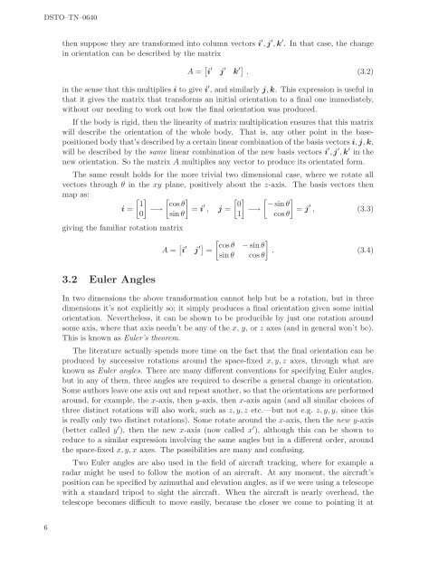
DSTO–TN–0640then suppose they are transformed in<strong>to</strong> column vec<strong>to</strong>rs i ′ , j ′ , k ′ . In that case, the changein orientation can be described by the matrixA = [ i ′ j ′ k ′] . (3.2)in the sense that this multiplies i <strong>to</strong> give i ′ , and similarly j, k. This expression is useful inthat it gives the matrix that transforms an initial orientation <strong>to</strong> a final one immediately,without our needing <strong>to</strong> work out how the final orientation was produced.If the body is rigid, then the linearity of matrix multiplication ensures that this matrixwill describe the orientation of the whole body. That is, any other point in the basepositionedbody that’s described by a certain linear combination of the basis vec<strong>to</strong>rs i, j, k,will be described by the same linear combination of the new basis vec<strong>to</strong>rs i ′ , j ′ , k ′ in thenew orientation. So the matrix A multiplies any vec<strong>to</strong>r <strong>to</strong> produce its orientated form.The same result holds for the more trivial two dimensional case, where we rotate allvec<strong>to</strong>rs through θ in the xy plane, positively about the z-axis. The basis vec<strong>to</strong>rs thenmap as:[ 1i = −→0][ ] [ cos θ= i ′ 0, j = −→sinθ 1][ ] − sinθ= j ′ , (3.3)cos θgiving the familiar rotation matrixA = [ [ ]i ′ j ′] cos θ − sinθ=. (3.4)sinθ cos θ3.2 Euler AnglesIn two dimensions the above transformation cannot help but be a rotation, but in threedimensions it’s not explicitly so; it simply produces a final orientation given some initialorientation. Nevertheless, it can be shown <strong>to</strong> be producible by just one rotation aroundsome axis, where that axis needn’t be any of the x, y, or z axes (and in general won’t be).This is known as Euler’s theorem.The literature actually spends more time on the fact that the final orientation can beproduced by successive rotations around the space-fixed x, y, z axes, through what areknown as Euler angles. There are many different conventions for specifying Euler angles,but in any of them, three angles are required <strong>to</strong> describe a general change in orientation.Some authors leave one axis out and repeat another, so that the orientations are performedaround, for example, the x-axis, then y-axis, then x-axis again (and all similar choices ofthree distinct rotations will also work, such as z, y, z etc.—but not e.g. z, y, y, since thisis really only two distinct rotations). Some rotate around the x-axis, then the new y-axis(better called y ′ ), then the new x-axis (now called x ′ ), although this can be shown <strong>to</strong>reduce <strong>to</strong> a similar expression involving the same angles but in a different order, aroundthe space-fixed x, y, x axes. The possibilities are many and confusing.Two Euler angles are also used in the field of aircraft tracking, where for example aradar might be used <strong>to</strong> follow the motion of an aircraft. At any moment, the aircraft’sposition can be specified by azimuthal and elevation angles, as if we were using a telescopewith a standard tripod <strong>to</strong> sight the aircraft. When the aircraft is nearly overhead, thetelescope becomes difficult <strong>to</strong> move easily, because the closer we come <strong>to</strong> pointing it at6


