Using Rotations to Build Aerospace Coordinate Systems - Defence ...
Using Rotations to Build Aerospace Coordinate Systems - Defence ...
Using Rotations to Build Aerospace Coordinate Systems - Defence ...
You also want an ePaper? Increase the reach of your titles
YUMPU automatically turns print PDFs into web optimized ePapers that Google loves.
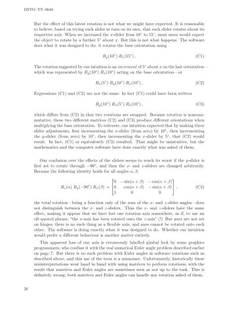
DSTO–TN–0640But the effect of this latest rotation is not what we might have expected. It is reasonable<strong>to</strong> believe, based on trying each slider in turn on its own, that each slider rotates about itsrespective axis. When we increased the x-slider from 10 ◦ <strong>to</strong> 15 ◦ , most users would expectthe object <strong>to</strong> rotate by a further 5 ◦ about x. But this is not what happens. The softwaredoes what it was designed <strong>to</strong> do: it rotates the base orientation usingR y (10 ◦ ) R x (15 ◦ ).(C1)The rotation suggested by our intuition is an increment of 5 ◦ about x on the last orientation—which was represented by R y (10 ◦ ) R x (10 ◦ ) acting on the base orientation—orR x (5 ◦ ) R y (10 ◦ ) R x (10 ◦ ).(C2)Expressions (C1) and (C2) are not the same. In fact (C1) could have been writtenR y (10 ◦ ) R x (5 ◦ ) R x (10 ◦ ),(C3)which differs from (C2) in that two rotations are swapped. Because rotation is noncommutative,these two different matrices (C2) and (C3) produce different orientations whenmultiplying the base orientation. To reiterate, our intuition expected that by making threeslider adjustments, first incrementing the x-slider (from zero) by 10 ◦ , then incrementingthe y-slider (from zero) by 10 ◦ , then incrementing the x-slider by 5 ◦ , that (C2) wouldresult. In fact, (C1) or equivalently (C3) resulted. That might be unintuitive, but themathematics and the computer software have done exactly what was asked of them.Our confusion over the effects of the sliders seems <strong>to</strong> reach its worst if the y-slider isfirst set <strong>to</strong> rotate through −90 ◦ , and then the x- and z-sliders are changed arbitrarily.Because the following identity holds for all angles α, β,⎡⎤0 − sin(α + β) − cos(α + β)R z (α) R y (−90 ◦ ) R x (β) = ⎣0 cos(α + β) − sin(α + β) ⎦ ,1 0 0(C4)the <strong>to</strong>tal rotation—being a function only of the sum of the x- and z-slider angles—doesnot distinguish between the x- and z-sliders. Thus the x- and z-sliders have the sameeffect, making it appear that we have lost one rotation axis somewhere, as if, <strong>to</strong> use anoft-quoted phrase, “the x-axis has been rotated on<strong>to</strong> the z-axis” (!) But axes are not se<strong>to</strong>n hinges; there is no such thing as a flexible axis, and axes cannot be rotated on<strong>to</strong> eachother. The software is doing exactly what it was designed <strong>to</strong> do. Whether our intuitionwould prefer a different behaviour is another matter entirely.This apparent loss of one axis is erroneously labelled gimbal lock by some graphicsprogrammers, who confuse it with the real numerical Euler angle problem described earlieron page 7. But there is no such problem with Euler angles in software rotations such asdescribed above, and this use of the term is a misnomer. Unfortunately, his<strong>to</strong>rically thesemisinterpretations went hand in hand with using matrices <strong>to</strong> perform rotations, with theresult that matrices and Euler angles are sometimes seen as not up <strong>to</strong> the task. This isdefinitely wrong; both matrices and Euler angles can handle any rotation asked of them.26


