

Using Rotations to Build Aerospace Coordinate Systems - Defence ...
Using Rotations to Build Aerospace Coordinate Systems - Defence ...
Using Rotations to Build Aerospace Coordinate Systems - Defence ...

Create successful ePaper yourself
Turn your PDF publications into a flip-book with our unique Google optimized e-Paper software.
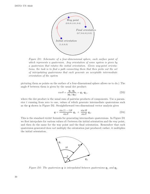
DSTO–TN–0640Way point(0.9, 0.1, 0.1, 0.4)Final orientation(0.7, 0.6, 0.2, 0.3)Initial orientation(1, 0, 0, 0)Figure D1: Schematic of a four-dimensional sphere, each surface point ofwhich represents a quaternion. Any orientation of some system is given bya quaternion that rotates the initial orientation. Given way-point orientations,the task is <strong>to</strong> find a path connecting them that then picks out the se<strong>to</strong>f interpolating quaternions that each generate an acceptable intermediateorientation of the systempicturing them as points on the surface of a four-dimensional sphere allows us <strong>to</strong> do.) Theangle θ between them is given by the usual dot product:cos θ = q 1·q 2|q 1 | |q 2 | = q 1·q 2 , (D3)where the dot product is the usual sum of pairwise products of components. Use a parametert running from zero <strong>to</strong> one, values of which generate intermediate quaternions suchas the q shown in Figure D2. Straightforward two-dimensional vec<strong>to</strong>r analysis givesq =sin(1 − t)θsinθq 1 + sintθsinθ q 2 .(D4)This is the standard slerp formula for generating intermediate quaternions. In Figure D1we first interpolate for various values of t between the initial orientation and the way point,and then do the same for the way point and the final orientation. Remember that eachquaternion generated does not multiply the orientation just produced; rather, it multipliesthe initial orientation.q 1q 2tθqθFigure D2: The quaternion q is interpolated between quaternions q 1 and q 230


