

Using Rotations to Build Aerospace Coordinate Systems - Defence ...
Using Rotations to Build Aerospace Coordinate Systems - Defence ...
Using Rotations to Build Aerospace Coordinate Systems - Defence ...

Create successful ePaper yourself
Turn your PDF publications into a flip-book with our unique Google optimized e-Paper software.
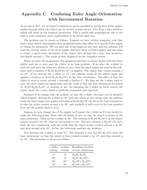
DSTO–TN–0640Appendix C Confusing Euler Angle Orientationwith Incremental RotationAs we saw in Sect. 3.2, an object’s orientation can be specified by giving three Euler angles:angles through which the object can be turned in some preset order from a base position,which will result in the required orientation. This is useful and unambiguous, but it canlead <strong>to</strong> some confusion when implemented in an overly rigid way.The problem can be shown as follows. Suppose we have written computer code thatdraws some object, and supplies three graphical sliders that allow us <strong>to</strong> specify Euler angles<strong>to</strong> change its orientation. We can alter any of the angles at any time, and the software willread the current values of the three angles, interpret them as Euler angles, and use them<strong>to</strong> rotate a preset base orientation of the object, first around the x-axis, then around y,and finally around z. The result is then displayed on the computer screen.When we start the programme, this graphical interface is always drawn with the threesliders each set <strong>to</strong> zero, and the object in its base position. If we alter the x-slider <strong>to</strong>read 10 ◦ and leave the other two sliders at zero, then the three angles are read by the software,and a rotation of R z (0)R y (0)R x (10 ◦ ) is applied. The object duly rotates around xby 10 ◦ . If we increase the x-slider <strong>to</strong> 15 ◦ , the software reads all the sliders again andapplies a rotation of R z (0)R y (0)R x (15 ◦ ) <strong>to</strong> the base orientation. The effect is that theobject is seen <strong>to</strong> rotate around x through a further 5 ◦ . We then set the x-slider back <strong>to</strong>zero, the three angles are again read, and the result is that the base orientation is rotatedby R z (0)R y (0)R x (0), or nothing at all. So changing the x-slider by itself rotates theobject about the x-axis, which is perfectly reasonable and expected.Similarly if we change only the y-slider, or only the z-slider, the same sort of intuitiveeffects happen. Setting the y-slider <strong>to</strong> 10 ◦ with the others at zero means that the softwarereads the three angles and applies a rotation of R z (0)R y (10 ◦ )R x (0) <strong>to</strong> the base orientation,so that the object rotates around y by 10 ◦ , and similarly it will revert <strong>to</strong> the base positionif we set the y-slider back <strong>to</strong> zero.Suppose we now change two of the angles; we’ll ignore the z-slider as it’s not needed <strong>to</strong>make the following point. Start with all sliders at zero so that the object is drawn in thebase orientation. Then set the x-slider <strong>to</strong> 10 ◦ . The rotation is R y (0)R x (10 ◦ ), so the objectrotates around x by 10 ◦ . Now set the y-slider <strong>to</strong> 10 ◦ . The new rotation is R y (10 ◦ )R x (10 ◦ )from the base orientation, with the result that the object is first rotated around x by 10 ◦and then around y by 10 ◦ . So far, the behaviour matches our intuition.Now increase the x-slider <strong>to</strong> read 15 ◦ . The rotation is now R y (10 ◦ )R x (15 ◦ ) from thebase orientation, so that the object is first rotated around x by 15 ◦ and then around yby 10 ◦ . The procedure is shown as follows:x-slider y-slider Resulting rotationsetting setting of base orientation0 0 R y (0) R x (0)10 ◦ 0 R y (0) R x (10 ◦ )10 ◦ 10 ◦ R y (10 ◦ ) R x (10 ◦ )15 ◦ 10 ◦ R y (10 ◦ ) R x (15 ◦ )25


