


You also want an ePaper? Increase the reach of your titles
YUMPU automatically turns print PDFs into web optimized ePapers that Google loves.
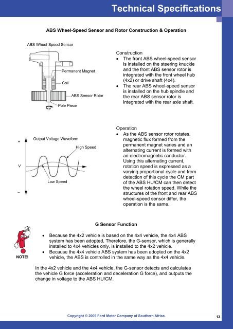
Technical SpecificationsABS Wheel-Speed Sensor and Rotor Construction & OperationABS Wheel-Speed SensorPermanent MagnetCoilABS Sensor RotorPole PieceConstruction• The front ABS wheel-speed sensoris installed on the steering knuckleand the front ABS sensor rotor isintegrated with the front wheel hub(4x2) or drive shaft (4x4).• The rear ABS wheel-speed sensoris installed on the hub spindle andthe rear ABS sensor rotor isintegrated with the rear axle shaft.+V_Output Voltage WaveformLow SpeedHigh SpeedOperation• As the ABS sensor rotor rotates,magnetic flux formed from thepermanent magnet varies and analternating current is formed withan electromagnetic conductor.Using this alternating current,rotation speed is expressed as avarying proportional cycle and fromdetection of this cycle the CM partof the ABS HU/CM can then detectthe wheel rotation speed. While thestructures of the front and rear ABSwheel-speed sensor differ, theoperation is the same.G Sensor FunctionNOTE!• Because the 4x2 vehicle is based on the 4x4 vehicle, the 4x4 ABSsystem has been adopted, Therefore, the G-sensor, which is generallyinstalled to 4x4 vehicles only, is installed to the 4x2 vehicle.• Because the 4x4 vehicle ABS system has been adopted on the 4x2vehicle, the ABS is controlled in the same way as the 4x4 vehicle.In the 4x2 vehicle and the 4x4 vehicle, the G-sensor detects and calculatesthe vehicle G force (acceleration and deceleration G force), and outputs thechange in voltage to the ABS HU/CM.Copyright © 2009 <strong>Ford</strong> Motor Company of Southern Africa. 13