Installation Manual - Fireplaces
Installation Manual - Fireplaces
Installation Manual - Fireplaces

Create successful ePaper yourself
Turn your PDF publications into a flip-book with our unique Google optimized e-Paper software.
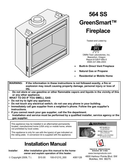
564 SSGreenSmartFireplaceTested and Listed byOMNI-Test Laboratories, Inc.Beaverton, OregonReport # 028-F-80b-5ANSI Z21.88b-2003• Built-In Direct Vent Fireplace• Natural Gas or Propane• Residential or Mobile HomeWARNING: If the information in these instructions is not followed exactly, a fire orexplosion may result causing property damage, personal injury or loss oflife.- Do not store or use gasoline or other flammable vapors and liquids in the vicinity of thisor any other appliance.WHAT TO DO IF YOU SMELL GAS• Do not try to light any appliance.• Do not touch any electrical switch; do not use any phone in your building.• Immediately call gas supplier from a neighbor's phone. Follow the gas supplier'sinstructions.• If you cannot reach your gas supplier, call the fire department.- <strong>Installation</strong> and service must be performed by a qualified installer, service agency or thegas supplier.This appliance may be installed in an aftermarket permanentlylocated, manufactured home (USA only) or mobile home, wherenot prohibited by local codes.This appliance is only for use with the type(s) of gas indicated onthe rating plate. A conversion kit is supplied with the appliance.<strong>Installation</strong> <strong>Manual</strong>Installer:After installation give this manual to the homeownerand explain operation of this heater.© Copyright 2009, T.I. $10.00 100-01210_000 4081126www.travisproducts.com4800 Harbour Pointe Blvd. SWMukilteo, WA 98275
2 IntroductionOverviewThis manual details the installation requirementsfor the 564 GS fireplace. For operating andmaintenance instructions, refer to the 564 GSOwner's <strong>Manual</strong> (part # 100-01211).Listing DetailsThis appliance was listed by OMNI Test Labs toANSI Z21.88 - report # 028-F-80b-5. The listinglabel is attached to the appliance near the gascontrol valve. A copy is shown to the right.IAS (ICBO) ApprovalThis appliance was listed by OMNI Test Labs - IAS# TL130.Massachusetts ApprovalThis manual has been submitted to theMassachusetts Board of State Examiners ofPlumbers and Gas FittersNational Fireplace Institute© Travis Industries 4081126 100-01210_000
Table of Contents 3IntroductionOverview ............................................................................. 2Listing Details ...................................................................... 2Safety PrecautionsSafety Precautions .............................................................. 4Features and SpecificationsFeatures .............................................................................. 6<strong>Installation</strong> Options .............................................................. 6Heating Specifications ......................................................... 6Dimensions ......................................................................... 6<strong>Installation</strong>Packing List ......................................................................... 7Additional Items Required ................................................... 7<strong>Installation</strong> Overview ........................................................... 7Recommended <strong>Installation</strong> Procedure ................................ 7Top Stand-Off Assembly ..................................................... 9Converting the Fireplace to Top Vent Configuration ........... 10Fireplace Placement Requirements .................................... 12Clearances ...................................................................... 12Raised <strong>Fireplaces</strong> ............................................................ 12Min. Framing Dims. - Rear Vent Configuration ........................... 13Min. Framing Dims. - Top Vent Configuration ................. 14Nailing Brackets .............................................................. 15Corner <strong>Installation</strong>s - Rear Vent Configuration ................ 16Corner <strong>Installation</strong>s - Top Vent Configuration .................. 17Gas Line Requirements ...................................................... 18Fuel ................................................................................. 18Gas Line Connection ....................................................... 18Gas Inlet Pressure ........................................................... 18Gas Line Location............................................................ 18Electrical Connection (required) .......................................... 20Optional Wall Switch or Thermostat <strong>Installation</strong> .................. 21Vent Requirements ............................................................. 22Vent Clearances .............................................................. 22Altitude Considerations .................................................... 22Approved Vent ................................................................. 23Vent <strong>Installation</strong> ............................................................... 23Approved Vent Configurations ............................................ 24Restrictor Position ........................................................... 24Exhaust Restrictor Adjustment ........................................ 24Intake Restrictor Adjustment ........................................... 25Diffuser Plate Adjustment ................................................ 26Rear Vent Config. W Horizontal Term. (no vertical rise) ..... 27Rear Vent Config. W Horizontal Term. (w vertical rise) ....... 28Rear Vent Configuration with Vertical Termination .............. 29Top Vent Configuration with Horizontal Termination ........... 30Top Vent Configuration with Vertical Termination ............... 31Termination Requirements .................................................. 32<strong>Installation</strong> (continued)Hearth Requirements .......................................................... 33Facing Requirements .......................................................... 34Drywall <strong>Installation</strong> .......................................................... 34Facing Overview ............................................................. 35Optional Faceplates – Sizing Chart ................................. 35Thin Facing <strong>Installation</strong> ................................................... 36Thick Facing <strong>Installation</strong> .................................................. 38Thick Facing <strong>Installation</strong> with FPX Arched Faces............ 39Mantel Requirements .......................................................... 41Install Example - Build-Out (Dog-House) w Hor. Term. ...... 42Install Example - Build-In w Hor. Term. ............................... 43Finalizing the <strong>Installation</strong>Steps for Finalizing the <strong>Installation</strong> ..................................... 44Air Shutter Adjustment .................................................... 45Glass Frame Removal and <strong>Installation</strong> ............................... 46Log Set <strong>Installation</strong> ............................................................. 48LP Conversion Instructions ................................................. 55Optional EquipmentFireback <strong>Installation</strong> ............................................................ 58Grill <strong>Installation</strong> ................................................................... 59GreenSmart Remote Control <strong>Installation</strong> ......................... 60IndexIndex ................................................................................... 72© Travis Industries 4081126 100-01210_000
4 Safety PrecautionsSafety Warnings:• Failure to follow all of the requirements may result in property damage, bodily injury, or even death.• This unit must be installed by a qualified installer to prevent the possibility of an explosion.• This appliance must be installed in accordance with all local codes, if any; if not, in U.S.A. followANSI Z223.1 and NFPA 54(88).• A manufactured home (USA only) or mobile home OEM installation must conform with theManufactured Home Construction and Safety Standard, Title 24 CFR, Part 3280, or, when such astandard is not applicable, the Standard for Manufactured Home <strong>Installation</strong>s, ANSI/NCSBCSA225.1, or Standard for Gas Equipped Recreational Vehicles and Mobile Housing, CSA Z240.4. Thisappliance may be installed in Manufactured Housing only after the home is site located.• All exhaust gases must be vented outside the structure of the living-area. Combustion air is drawnfrom outside the living-area structure. The venting must not be connected to a chimney flue serving aseparate solid-fuel burning appliance.• Notify your insurance company before hooking up this fireplace.• The room heater should be inspected before use and at least annually by a qualified service person.More frequent cleaning may be required due to excessive lint from carpeting, bedding material, etc.• The instructions in this manual must be strictly adhered to. Do not use makeshift methods orcompromise in the installation. Improper installation will void the warranty and safety listing.• This heater is approved for use with natural gas (NG) or propane (LP). Burning the incorrect fuel willvoid the warranty and safety listing and may cause an extreme safety hazard. Direct questions aboutthe type of fuel used to your dealer. Check the label and flame adjust knob on the gas control valve.• Contact your local building officials to obtain a permit and information on any installation restrictionsor inspection requirements in your area.• If the flame becomes sooty, dark orange in color, or extremely tall, do not operate the heater. Callyour dealer and arrange for proper servicing.• It is imperative that control compartments, screens, or circulating air passageways of the heater bekept clean and free of obstructions. These areas provide the air necessary for safe operation.• Do not operate the heater if it is not operating properly in any fashion or if you are uncertain. Callyour dealer for a full explanation of your heater and what to expect.• Do not store or use gasoline or other flammable liquids in the vicinity of this heater.• Do not operate if any portion of the heater was submerged in water or if any corrosion occurs.• Do not place clothing or other flammable items on or near the heater. Because this heater can becontrolled by a thermostat there is a possibility of the heater turning on and igniting any items placedon or near it.• Light the heater using the built-in igniter. Do not use matches or any other external device to lightyour heater.• Never remove, replace, modify or substitute any part of the heater unless instructions are given in thismanual. All other work must be done by a trained technician. Don't modify or replace orifices.• The viewing glass should be opened only for conducting service.• Any safety screen or guard removed for servicing must be replaced prior to operating the heater.Travis Industries 4081126 100-01210_000
Safety Warnings (continued):Safety Precautions 5• Allow the heater to cool before carrying out any maintenance or cleaning.• Operate the heater according to the instructions included in this manual.• If the main burners do not start correctly turn the gas off and call your dealer for service.• This unit is not for use with solid fuel.• Do not place anything inside the firebox (except the included fiber logs).• If the fiber logs become damaged, replace with Travis Industries log set.• Do not throw this manual away. This manual has important operating and maintenance instructionsthat you will need at a later time. Always follow the instructions in this manual.• Do not touch the hot surfaces of the heater. Educate all children of the danger of a high-temperatureheater. Young children should be supervised when they are in the same room as the heater.• Due to the high temperature, the heater should be located out of traffic and away from furniture anddraperies.• Instruct everyone in the house how to shut gas off to the appliance and at the gas main shutoff valve.The gas main shutoff valve is usually next to the gas meter or propane tank and requires a wrench toshut off.• Travis Industries, Inc. grants no warranty, implied or stated, for the installation ormaintenance of your heater, and assumes no responsibility of any consequential damage(s).© Travis Industries 4081126 100-01210_000
8 <strong>Installation</strong> (for qualified installers only)Massachusetts RequirementsNOTE: The following requirements reference various Massachusetts and national codes not contained in this document.Requirements for the Commonwealth of MassachusettsFor all side wall horizontally vented gas fueled equipment installed in every dwelling, building or structure used in whole or inpart for residential purposes, including those owned or operated by the Commonwealth and where the side wall exhaust venttermination is less than seven (7) feet above finished grade in the area of the venting, including but not limited to decks andporches, the following requirements shall be satisfied:<strong>Installation</strong> of Carbon Monoxide DetectorsAt the time of installation of the side wall horizontal vented gas fueled equipment, the installing plumber or gasfitter shallobserve that a hard wired carbon monoxide detector with an alarm and battery back-up is installed on the floor level where thegas equipment is to be installed. In addition, the installing plumber or gasfitter shall observe that a battery operated or hardwired carbon monoxide detector with an alarm is installed on each additional level of the dwelling, building or structure servedby the side wall horizontal vented gas fueled equipment. It shall be the responsibility of the property owner to secure theservices of qualified licensed professionals for the installation of hard wired carbon monoxide detectors.In the event that the side wall horizontally vented gas fueled equipment is installed in a crawl space or an attic, the hard wiredcarbon monoxide detector with alarm and battery back-up may be installed on the next adjacent floor level.In the event that the requirements of this subdivision can not be met at the time of completion of installation, the owner shallhave a period of thirty (30) days to comply with the above requirements; provided, however, that during said thirty (30) dayperiod, a battery operated carbon monoxide detector with an alarm shall be installed.Approved Carbon Monoxide DetectorsEach carbon monoxide detector as required in accordance with the above provisions shall comply with NFPA 720 and beANSI/UL 2034 listed and IAS certified.SignageA metal or plastic identification plate shall be permanently mounted to the exterior of the building at a minimum height of eight(8) feet above grade directly in line with the exhaust vent terminal for the horizontally vented gas fueled heating appliance orequipment. The sign shall read, in print size no less than one-half (1/2) inch in size, “GAS VENT DIRECTLY BELOW. KEEPCLEAR OF ALL OBSTRUCTIONS”.InspectionThe state or local gas inspector of the side wall horizontally vented gas fueled equipment shall not approve the installationunless, upon inspection, the inspector observes carbon monoxide detectors and signage installed in accordance with theprovisions of 248 CMR 5.08(2)(a)1 through 4.ExemptionsThe following equipment is exempt from 248 CMR 5.08(2)(a)1 through 4:• The equipment listed in Chapter 10 entitled “Equipment Not Required To Be Vented” in the most current edition of NFPA 54as adopted by the Board; and• Product Approved side wall horizontally vented gas fueled equipment installed in a room or structure separate from thedwelling, building or structure used in whole or in part for residential purposes.MANUFACTURER REQUIREMENTSGas Equipment Venting System ProvidedWhen the manufacturer of Product Approved side wall horizontally vented gas equipment provides a venting system design orventing system components with the equipment, the instructions provided by the manufacturer for installation of the equipmentand the venting system shall include:• Detailed instructions for the installation of the venting system design or the venting system components; and• A complete parts list for the venting system design or venting system.Gas Equipment Venting System NOT ProvidedWhen the manufacturer of a Product Approved side wall horizontally vented gas fueled equipment does not provide the partsfor venting the flue gases, but identifies “special venting systems”, the following requirements shall be satisfied by themanufacturer:• The referenced “special venting system” instructions shall be included with the appliance or equipment installationinstructions; and• The “special venting systems” shall be Product Approved by the Board, and the instructions for that system shall include aparts list and detailed installation instructions.A copy of all installation instructions for all Product Approved side wall horizontally vented gas fueled equipment, all ventinginstructions, all parts lists for venting instructions, and/or all venting design instructions shall remain with the appliance orequipment at the completion of the installation.See Gas Connection section for additional Commonwealth of Massachusetts requirements.Travis Industries 4081126 100-01210_000
10 <strong>Installation</strong> (for qualified installers only)Top Vent or Rear Vent ConfigurationThis appliance is shipped in the rear vent configuration. To change to the top vent configuration, followthe directions below.NOTE: the vent configuration affects several aspects of installation (framing, maximum vent rise,maximum vent run). Make sure the vent configuration is correct prior to installation. You may wish toconfigure the diffuser when changing the vent configuration.Converting the Fireplace to Top Vent ConfigurationRemove and discard theheat shield. Replace the 4removed screws.NOTE: Use a magnetic-tippednutdriver on these screws - takecare to prevent the screws fromfalling into the fireplace.Top of FireplaceBack of FireplaceRemove the 4 screws securing theouter flue assembly. Place thescrews and assembly aside.Remove the 4 screws securing theintake cover plate. Place the screwsand cover plate aside.Remove the 4 screws securing theinner flue assembly. Place thescrews and assembly aside.Remove and discard theinsulation found below thelarge cover plate.Travis Industries 4081126 100-01210_000
12 <strong>Installation</strong> (for qualified installers only)Fireplace Placement Requirements• The fireplace requires a 1/2" (13mm) clearance from the angled sides and back of the fireplace to theframing members. No material (insulation, framing, etc.) may be placed into this area.• Fireplace must be installed on a level surface capable of supporting the fireplace and vent• Fireplace must be placed directly on wood or non-combustible surface (not on linoleum or carpet)• This heater may be placed in a bedroom. Please be aware of the large amount of heat this applianceproduces when determining a location.Clearances• When installed, walls in front of the fireplace must be a minimum 1" (25mm) to the side of thefireplace.• Due to the high temperature, the heater should be located out of traffic and away from furniture anddraperies.• Fireplace must be placed so the vents below and above the glass do not become blocked.Raised <strong>Fireplaces</strong>• The fireplace (and hearth, if desired) may be placed on a platform designed to support the fireplace(155 Lbs.70 Kg) and vent.Travis Industries 4081126 100-01210_000
<strong>Installation</strong> (for qualified installers only) 13Minimum Framing Dimensions - Rear Vent ConfigurationHINT: place the fireplace so the centerline is at least 5" (127mm) from bothvertical framing members at the rear (thisallows the vent to pass through theframing without modfications)Included Firestop (required)Part # 250-00747Vent Clearances for 8" (203mm) dia. Vent:1" (25mm) to the sides, 1" (25mm) below,and 4" (102mm) above the vent tocombustibles.Minimum 38" (965mm)Fireplace Enclosure Height 32-1/2"826mmCenter of Rear Vent24-1/4"616mmRoute theelectrical line toa position to theleft rear of thefireplace.33-1/2"851mm19-1/4"489mm36-1/2"927mm16-1/2"419mmThe on/off switch/thermostat wire (ifused) should be routed to a locationnear the right front of the fireplace.© Travis Industries 4081126 100-01210_000
14 <strong>Installation</strong> (for qualified installers only)Minimum Framing Dimensions - Top Vent ConfigurationRoute the electrical line toa position to the left rearof the fireplace.33-1/2"851mm36-1/2"927mm16-1/2"419mmMinimum enclosure height = 36-1/4" (921mm)WARNING: A cut-out for the gas linemay be required on the framing. Seethe dimensions under "Gas LineConnection" for details.The on/off switch/thermostat wire (ifused) should be routed to a locationnear the right front of the fireplace.Travis Industries 4081126 100-01210_000
<strong>Installation</strong> (for qualified installers only) 15Nailing BracketsThere are four nailing bracketson the front of the fireplace.Follow the directions below toprepare the nailing brackets.Once in place, nail or screw thenailing brackets to the framing.NOTE: Additional nailingbrackets are provided alongthe base of the fireplace.Use these brackets if notusing the front brackets.WARNING:Make sure the fireplace issquare and plumb whenplaced in the framing.Measured corner-tocorner,the fireplaceshould be square (approx.47-1/8" (1197mm) for eachdimension). Use shims toinsure the fireplace issquare.1/2" (13mm)DrywallTOP VIEWFramingFor installations using1/2" (13mm) facing foldthe larger tab out 90°(use a screwdriver ifnecessary).FireplaceDrywallNailing Bracket5/8" (0.625mm) DrywallFor installations using5/8" (0.625mm) drywallfold the shorter tab out90° (use a screwdriver ifnecessary).TOP VIEWFireplaceFramingDrywallNailing Bracket© Travis Industries 4081126 100-01210_000
16 <strong>Installation</strong> (for qualified installers only)Corner <strong>Installation</strong>s - Rear Vent ConfigurationA typical 45° installation uses the framing dimensions shown in the illustration below (NOTE: allclearances still apply).7" (178mm)Approximate(varies due to ventinstallation)NOTE:Most installationsuse:6" (152mm) Section for 2x6(51mm X 152mm) Walls4" (102mm) Section for 2x4(51mm X 102mm) Walls44-1/2" Min.1130mmMinimum 1" (25mm)Clearance564 SS FirestopMinimum 1/2" (13mm)ClearanceTravis Industries 4081126 100-01210_000
<strong>Installation</strong> (for qualified installers only) 17Corner <strong>Installation</strong>s - Top Vent ConfigurationA typical 45° installation uses the framing dimensions shown in the illustration below (NOTE: allclearances still apply).44-1/2" Min.1130mm14-1/4"362mmMinimum 1/2" (13mm)Clearance © Travis Industries 4081126 100-01210_000
18 <strong>Installation</strong> (for qualified installers only)Gas Line RequirementsFuelMASSACHUSETTS INSTALLATIONS - WARNING:THIS PRODUCT MUST BE INSTALLED BY A LICENSED PLUMBER OR GAS FITTER WHEN INSTALLED WITHIN THECOMMONWEALTH OF MASSACHUSETTS.OTHER MASSACHUSETTS CODE REQUIREMENTS:• Flexible connector must not be longer than 36 inches.• Shutoff valve must be a “T” handle gas cock.• Only direct vent sealed combustion products are approved for bedrooms or bathrooms.• Fireplace dampers must be removed or welded in the open position prior to the installation of a fireplace insert or gas log.• A carbon monoxide (CO) detector is required in the same room as the appliance.• The gas line must be installed in accordance with all local codes, if any; if not, follow ANSI 223.1 andthe requirements listed below.• The fireplace and gas control valve must be disconnected from the gas supply piping during anypressure testing of that system at test pressures in excess of 1/2 psig. For pressures under 1/2 psig,isolate the gas supply piping by closing the manual shutoff valve.• Leak test all gas line joints and the gas control valve prior to and after starting the fireplace.• This fireplace is designed either for natural gas or for propane (but not for both). Check the sticker on the top ofthe gas control valve to make sure the correct fuel is used.Gas Line Connection• <strong>Installation</strong> must be performed by a qualified installer, service agency or the gas supplier (In Massachusetts alicensed plumber/gasfitter).Gas Inlet PressureNatural GasPropaneStandard Input Pressure7" W.C. (1.74 kPA)13" W.C. (2.73 kPA)• If the pressure is not sufficient, make sure the piping used is large enough, the supply regulator is adequatelyadjusted, and the total gas load for the residence does not exceed the amount supplied.• The supply regulator (the regulator that attaches directly to the residence inlet or to the propane tank) shouldsupply gas at the suggested input pressure listed above. Contact the local gas supplier if the regulator is at animproper pressure.Travis Industries 4081126 100-01210_000
Gas Line LocationRight Side Gas Inlet (preferred)<strong>Installation</strong> (for qualified installers only) 19A 6" (152mm) flex tube and shutoffvalve is included with the fireplace.The shutoff valve accepts a 1/2"MPT.A 3" (76mm) high by 2" (51mm) wide opening islocated behind the gas inlet cover plate. It is 7-3/4"(197mm) behind the front and 1-3/4" (44mm) abovethe base of the fireplace.8-3/4"222mm13-3/4"349mmThe gas inlet is located 2-1/2"(64mm) above the base of thefireplace.You may remove this cover plate to install the gas line. Thecover plate has a 7/8" (.0875mm) diameter hole (coveredwith a push plug) in line with the gas inlet on the gas controlvalve. By rotating the plate 180° the hole may be re-located.You may also secure the plate in a customized location usingthe self-drilling screws.Left Side Gas InletA 3" (76mm) high by 2" (51mm) wide opening islocated behind the gas inlet cover plate. It is 4-3/4"(121mm) behind the front and 1-3/4" (44mm) abovethe base of the fireplace.A 6" (152mm) flex tube and shutoff valve isincluded with the fireplace. You may wish touse a 24" (610mm) flex tube. The shutoff valveaccepts a 1/2" MPT.8-3/4"222mmYou may wish to route the flex line alongthe front edge of the fireplace to conceal it.13-3/4"349mmYou may remove this cover plate to installthe gas line. The cover plate has a 7/8"(0.875mm) diameter hole (covered with apush plug). By rotating the plate 180° thehole may be re-located. You may alsosecure the plate in a customized locationusing the self-drilling screws.© Travis Industries 4081126 100-01210_000
20 <strong>Installation</strong> (for qualified installers only)Electrical Connection (required)• The electrical line to the grounded receptacle inside the fireplace must be installed by a qualifiedinstaller and must meet all local codes.• Make sure the household breaker is shut off prior to working on any electrical lines.• The appliance, when installed, must be electrically grounded in accordance with local codes or, in theabsence of local codes, with the National Electrical Code, ANSI/NFPA 70, or the Canadian ElectricalCode, CSA C22.1.• The electrical line must be a min. 14 gauge, and supply 120 Volts at 60 Hz (2 Amps).Caution:Label all wires prior to disconnection when servicing controls. Wiring errors can causeimproper and dangerous operation.a b c dTravis Industries 4081126 100-01210_000
<strong>Installation</strong> (for qualified installers only) 21Optional Wall Switch or Thermostat <strong>Installation</strong>Do not connect 110-120 VAC to the gas control valve or wiring system of this fireplace. The switch andwiring must be installed by a qualified installer.This fireplace includes an optional wall switch (with wire)to operate the fireplace burner without accessing theinternal on/off switch. A thermostat may be used instead.Route the wire from inside the fireplace, through thegrommet on either side of the fireplace near the gas inlet(see at right) to the switch. The wall switch (or thermostat)may bypass the fireplace on/off switch or be installed inparallel or series configuration (see below).OPTIONAL WALL SWITCH(included with fireplace)Place "WARNING"label on switch cover.Caution:Note:Warning:Label all wires prior to disconnection whenservicing controls. Wiring errors can causeimproper and dangerous operation.When using a GreenSmart remote, use thereceiver for on/off operation (do not use a wallswitch or thermostat).Make sure all wiring is secure and does notcontact hot or moving components.Parallel ConnectionThermostat / ExternalSwitch ONThermostat / ExternalSwitch OFFSeries ConnectionOn / Off SwitchONOn / Off SwitchOFFHeater is ON Heater is ON Thermostat /External Switch ONHeater is ON Heater is OFF Thermostat /External Switch OFFOn / Off SwitchONHeater is ONHeater is OFFOn / Off SwitchOFFHeater is OFFHeater is OFFTo wire the heater in parallel, follow the directions below: To wire the heater in series, follow the directions below:abaOn / Off SwitchOn / Off SwitchbThermostat(or External Switch) WirescThermostat(or External Switch) Wiresc© Travis Industries 4081126 100-01210_000
22 <strong>Installation</strong> (for qualified installers only)Vent Requirements• The gas appliance and vent system must be vented directly to the outside of the building, and neverbe attached to a chimney serving a separate solid fuel or gas-burning appliance. Each direct ventgas appliance must use it's own separate vent system.• In addition to the requirements listed here, follow the requirements provided with the vent.• A firestop is required whenever the vent penetrates a wall, floor, or ceiling (passes through framingmembers). Horizontal vent less than 48" (1219mm) above the fireplace must use the Travis Firestop(sku 250-00747 - it incorporates a 4" (102mm) clearance above, 1"( 25mm)clearance below and tothe sides of the vent). Other penetrations only require a 1" (25mm) clearance and may use astandard firestop (make sure the required 1" (25mm) clearance is met).• Always use the high-wind termination (if available from the vent manufacturer).Vent Clearances• The vent must maintain the required clearance to combustible materials to prevent a fire. Do not fillair spaces with insulation.Before 48" (1219mm)RiseAfter 48" (1219mm)RiseSides 1" (25mm) 1" (25mm)Above 4" (102mm) 1" (25mm)Below Horizontal or 45° Section 1" (25mm) 1" (25mm)Vertical TerminationRequired FirestopHorizontalTerminationUse a roof flashing and storm collarwhenever passing through the roofUse a firestop wheneverMin. 4" (102mm)passing through a ceiling1" (25mm) if a minimum 48"(1219mm) above theUse a support boxon exposed ventMin. 1"25mmMin. 1"25mmfireplace.Min. 1"25mmAltitude Considerations• This heater has been tested at altitudes ranging from sea level to 6,000 feet (1800M). In this testing we havefound that the heater, with its standard orifice, burns correctly with just an air shutter adjustment.• Failure to adjust the air shutter properly may lead to improper combustion which can create a safety hazard.Consult your dealer or installer if you suspect an improperly adjusted air shutter.Travis Industries 4081126 100-01210_000
Intake Restrictor Adjustment<strong>Installation</strong> (for qualified installers only) 25Position # 1 (open)1/4"SocketLoosen the two screwsholding the intakerestrictor in place..Position # 2 (closed)Slide the restrictor downto the lower position andtighten the screws.© Travis Industries 4081126 100-01210_000
26 <strong>Installation</strong> (for qualified installers only)Diffuser Plate AdjustmentCertain vent configurations require the diffuser plate to be adjusted (refer to the approved ventconfiguration charts for details). Position # 1 is stock (bent). Position # 2 is flattened. See the directionsbelow to change the diffuser to position #2.Firebox RoofBack Wall of FireboxRemove the exhaustrestrictor.1/4" Nutdriver1/4" NutdriverRemove the diffuser.DIFFUSER SIDE VIEWBefore (Stock - Position # 1)Bend the round portion of thediffuser so it is flat (position # 2).After (Position # 2)Secure the flatteneddiffuser plate with thescrews removed earlier.Replace the exhaustrestrictor (see “ExhaustRestrictor Adjustment”for restrictor settings).Travis Industries 4081126 100-01210_000
<strong>Installation</strong> (for qualified installers only) 27Rear Vent Configuration with Horizontal Termination (no vertical rise)• The termination must fall within the shaded area shown in the chart. Use the indicated restrictor anddiffuser positions.Optional 45 ElbowSee the charts below todetermine maximum ventTerminationVent with No 45 Elbow3 feet915mm0 feetmm0 feetmm4’ (max)610mm-Exhaust Restrictor:Remove the exhaust restrictorand replace the screws.-Intake Restrictor # 1 (stock)-Diffuser Position # 1 (stock)-Min. 4" (102mm) Horizontal Section-Max.48" (1.2m) Horizontal Section(s)Vent with 1 45 Elbow3 feet915mm0 feetmm0 feetmm2’ (max)1.2m-Exhaust Restrictor:Remove the exhaust restrictorand replace the screws.-Intake Restrictor # 1 (stock)-Diffuser Position # 1 (stock)-Min. 4" (102mm) Horizontal Section-Max. 24" (610mm) Horizontal Section(s)© Travis Industries 4110420 100-01210_000
28 <strong>Installation</strong> (for qualified installers only)Rear Vent Configuration with Horizontal Termination (with vertical rise)• The termination must fall within the shaded area shown in the chart. Use the indicated restrictor anddiffuser positions.• Up to four elbows (45° or 90°) may be used.• Only one horizontal elbow may be used.0 feet5 feet (1.5 m)10 feet (3 m)15 feet (4.5 m)20' max (6 m)22' max (6.7 m)15 feet (4.5 m)10 feet (3 m)5 feet (1.5 m)Exhaust Restrictor # 5Intake Restrictor # 2Diffuser Position # 2Exhaust Restrictor # 4Intake Restrictor # 2Diffuser Position # 2Exhaust Restrictor # 2Intake Restrictor # 1 (stock)Diffuser Position # 1 (stock)22' max (6.7 m)20 feet (6 m) 20 feet (6 m)15 feet (4.5 m)10 feet (3 m)5 feet (1.5 m)0 feet0 feet0 feet5 feet (1.5 m)10 feet (3 m)15 feet (4.5 m)20' max (6 m)H2This is considered a horizontalelbow (it does not matterwhether it turns right or left).It may be a 90° or 45° elbow.Horizontal length is calculated by addingboth lengths of horizontal run(Horizontal Length = H1 + H2).H1This is considered avertical elbowTravis Industries 4081126 100-01210_000
<strong>Installation</strong> (for qualified installers only) 29Rear Vent Configuration with Vertical Termination• The termination must fallwithin the shaded area shownin the chart. Use theindicated restrictor anddiffuser positions.• Up to four elbows (45° or 90°)may be used.• Only one horizontal elbowmay be used.40' max (12m)35 feet (10.5m)30 feet (9m)25 feet (7.5m)0 feet5 feet (1.5m)Exhaust Restrictor # 5Intake Restrictor # 2Diffuser Position # 2Exhaust Restrictor # 4Intake Restrictor # 2Diffuser Position # 2Exhaust Restrictor # 2Intake Restrictor # 2Diffuser Position # 220 feet (6m) 20 feet (6m)15 feet (4.5m)10 feet (3m)10 feet (3m)15 feet (4.5m)20' max (6m)40' max (12m)35 feet (10.5m)30 feet (9m)25 feet (7.5m)15 feet (4.5m)10 feet (3m)5 feet (1.5m)5 feet (1.5m)0 feet0 feet0 feet5 feet (1.5m)10 feet (3m)15 feet (4.5m)20' max (6m)H2This is considered a horizontalelbow (it does not matterwhether it turns right or left).It may be a 90° or 45° elbow.Horizontal length is calculated by addingboth lengths of horizontal run(Horizontal Length = H1 + H2).H1This is considered avertical elbow© Travis Industries 4081126 100-01210_000
30 <strong>Installation</strong> (for qualified installers only)Top Vent Configuration with Horizontal Termination• The termination must fall within the shaded area shown in the chart. Use the indicated restrictor anddiffuser positions.• Up to four elbows (45° or 90°) may be used.• May use 8" (203mm) or 6-5/8" (168mm) diameter vent (see page for 22 details).• Only one horizontal elbow may be used.0 feet5 feet (1.5m)10 feet (3m)15 feet (4.5m)20' max (6m)21' max (6.4m)5 feet (1.5m)Exhaust Restrictor # 5Intake Restrictor # 2Diffuser Position # 2Exhaust Restrictor # 4Intake Restrictor # 2Diffuser Position # 2Exhaust Restrictor # 2Intake Restrictor # 1 (stock)Diffuser Position # 1 (stock)20 feet (6m) 20 feet (6m)15 feet (4.5m)10 feet (3m)21' max (6.4m)15 feet (4.5m)10 feet (3m)5 feet (1.5m)0 feet0 feet0 feet5 feet (1.5m)10 feet (3m)15 feet (4.5m)20' max (6m)H2This is considered a horizontalelbow (it does not matterwhether it turns right or left).It may be a 90° or 45° elbow.Horizontal length is calculated by addingboth lengths of horizontal run(Horizontal Length = H1 + H2).H1This is considered avertical elbowTravis Industries 4081126 100-01210_000
<strong>Installation</strong> (for qualified installers only) 31Top Vent Configuration with Vertical Termination• The termination must fallwithin the shaded areashown in the chart. Usethe indicated restrictorand diffuser positions.• Up to four elbows (45° or90°) may be used.• Only one horizontalelbow may be used.• May use 8" (203mm) or6-5/8" (168mm) diametervent (see page for 22details).40' max (12m)35 feet (10.5m)30 feet (9m)25 feet (7.5m)0 feet5 feet (1.5m)10 feet (3m)15 feet (4.5m)20' max (6m)Exhaust Restrictor # 5Intake Restrictor # 2Diffuser Position # 2Exhaust Restrictor # 4Intake Restrictor # 2Diffuser Position # 2Exhaust Restrictor # 2Intake Restrictor # 1 (stock)20 feet (6m) 20 feet (6m)15 feet (4.5m)10 feet (3m)Diffuser Position # 240' max (12m)35 feet (10.5m)30 feet (9m)25 feet (7.5m)15 feet (4.5m)10 feet (3m)5 feet (1.5m)5 feet (1.5m)0 feet0 feet0 feet5 feet (1.5m)10 feet (3m)15 feet (4.5m)20' max (6m)H2This is considered a horizontalelbow (it does not matterwhether it turns right or left).It may be a 90° or 45° elbow.Horizontal length is calculated by addingboth lengths of horizontal run(Horizontal Length = H1 + H2).H1This is considered avertical elbow© Travis Industries 4081126 100-01210_000
32 <strong>Installation</strong> (for qualified installers only)Termination Requirements! Venting terminals shall not be recessed into a wall or siding.ABCDMinimum 9" (229mm) clearance from any door or windowMinimum 12" (305mm) above any grade, veranda, porch, deck or balconyMinimum 1" (25mm) from outside corner wallsNOTE: Clearance in accordance with local installation codes and the requirementsof the gas supplier.Minimum 1" (25mm) from inside corner wallsNOTE: Clearance in accordance with local installation codes and the requirementsof the gas supplier.RoofSurface11" Min.(279mm)6" Min.(152mm)RoofEavesEFGHIJKLMNMinimum 11" (279mm) clearance below unventilated soffits or roof surfacesMinimum 18" (457mm) clearance below ventilated soffitsMinimum 6" (152mm) clearance below roof eavesNOTE: Vinyl surfaces require 24" (610mm)NOTE: Clearance in accordance with local installation codes and the requirements of the gas supplier.Minimum 12" (305mm) clearance below a veranda, porch, deck or balconyNOTE: Permitted only if veranda, porch, deck, or balcony is fully open on a minumum of two sides beneath the floor.NOTE: Clearance in accordance with local installation codes and the requirements of the gas supplier.Minimum 48" (1219mm) clearance from any adjacent buildingMinimum 84" (2134mm) clearance above any grade when adjacent to public walkways or drivewaysNOTE: may not be used over a walkway or driveway shared by an adjacent buildingMinimum 9" (229mm) clearance to any nonmechanical air supply inlet to the building or the combustion air inletto any other appliance.Minimum 36" (914mm) clearance above any mechanical air supply inlet if within 10’ (3M) horizontallyMinimum 36" (914mm) from the area above the meter/regulator (vent outlet) - this extends 15’ (4.5M) above the regulatorNOTE: Clearance in accordance with local installation codes and the requirements of the gas supplier.Minimum 36" (914mm) from the meter/regulator (vent outlet)NOTE: Clearance in accordance with local installation codes and the requirements of the gas supplier.Minimum 12” (305mm) above the roof line (for vertical terminations)Minimum 24” (610mm) horizontal clearance to any surface (such as an exterior wall) – for vertical terminationsENMEEAKJGFDACIHLBNOTE: Measure clearances to the nearest edge of the exhaust hood.• Use the vinyl siding standoff when installing on an exterior with vinyl siding.• Vent termination must not be located where it will become plugged by snow or other materialTravis Industries 4081126 100-01210_000
Hearth Requirements<strong>Installation</strong> (for qualified installers only) 33Floor Mounted<strong>Fireplaces</strong>Do not build a hearth morethan 1" (25mm) above thebaseplate (this area mustremain clear for the access door).WARNING:If installed near carpet or othercombustible flooring, the fireplacemust be raised so the base of theunit is above the carpet surface orflooring material.A non-combustible hearth is not required. However, ifthe heater is installed next to the floor, we recommenda hearth to protect the flooring surface fromdiscoloration or other negative impact from the heater.Raised<strong>Fireplaces</strong>surface.Fireplace StandA hearth is not requiredwhen the fireplace israised above the flooring© Travis Industries 4081126 100-01210_000
34 <strong>Installation</strong> (for qualified installers only)Facing Requirements• This appliance is designed to allow for drywall (or other combustible facing) to contact the sides andtop of the front of the fireplace.• Tile or other non-combustible facing may be placed on the front of the fireplace (see "FacingOverview" on page 35 for further details).Drywall <strong>Installation</strong>Drywall <strong>Installation</strong> Drywall may beinstalled up to the front edge of the fireplace.If the fireplace is raised, drywall up to thebottom edge as well.DrywallDo not install drywall (or anyother combustible) in frontof the fireplace.TOP VIEWFramingFireplaceNailing BracketDrywallTravis Industries 4081126 100-01210_000
<strong>Installation</strong> (for qualified installers only) 35Facing OverviewUpgrade faces are available for this fireplace and may influence facing installation. Consult with yourTravis Dealer if you are using an upgrade face.Optional non-combustible facing may be installed on the fireplace. Use the guidelines below to determinethe location (also see the following pages for detailed diagrams.Tile Line Any non-combustible facing under 1" (25mm) thick (see "Thin Facing" on page 36).Masonry Line Any non-combustible over 1" (25mm) thick (see "Thick Facing" on page 38).Hearth LineNon-combustible hearth/facing should be installed up to this location (1" (25mm) above the baseof the fireplace). The fireplace may be raised to accommodate thicker hearth materials.Masonry LineTile LineTile LineMasonry LineTile LineMasonry LineMasonry LineTile LineHearth LineHearth LineTile LineMasonry LineTile LineMasonry LineNOTE: The hearth or facing can extend nogreater than 1'' (25mm) above the base of thefireplace. The fireplace may be raised toaccommodate thicker hearth materials.Optional Faceplates – Sizing ChartName Height Width NotesFPX Art., Clsc., Fr Ctry 29” (737mm) 36” (914mm) 61” Radius – May fit over top of tile facingWilmington 29” (737mm) 36” (914mm) May fit over top of tile facingVictorian Lace 27-1/2” (699mm) 32-3/8” (822mm) Optional facing buttes to edge of faceplate (tile line)Bungalow, Tree of Life 27-1/2” (699mm) 32-3/8” (822mm) Optional facing buttes to edge of faceplate (tile line)© Travis Industries 4081126 100-01210_000
36 <strong>Installation</strong> (for qualified installers only)Thin Facing <strong>Installation</strong> (tile, marble, or other non-combustible under 1" (25mm) thick)Upgrade faces are available for this fireplace and may influence facing installation. Consult with yourTravis Dealer if you are using an upgrade face.Tile LineTile LineDo not install tile (or other material)in front of the glass frame,convection channel, or access panelopenings. This area must remainopen to access internal componentsand for convection air.TOP VIEWFramingTileNOTE FOR FPX FACES:Facing is installed to thisedge of the fireplace.FPX arched faces require the FPX Face UpgradeKit (sku 98500683) and a triangular piece offacing in these upper corners. See theinstructions included with the7-1/2"face for furtherdetails.191mm1-5/8"41mm DrywallRaised <strong>Fireplaces</strong>:FireplaceNailing BracketFacing is installed 1" maximum(25mm) above the base of thefireplace.DrywallFRONT VIEWTile LineHearth LineFloor-Mounted <strong>Fireplaces</strong> or Raised Hearths:Build the hearth 1" max (25mm) above thebase of the fireplace. The fireplace may beraised to accommodate thicker hearth materials.1-1/2"38mm27-3/4"705mm1”32-1/2"1-7/8"826mm48mmTravis Industries 4081126 100-01210_000
<strong>Installation</strong> (for qualified installers only) 37Thin Facing <strong>Installation</strong> (tile, marble, under 1" (25mm) thick) - Side ViewRaised Fireplace(with no Hearth)SIDE OFFIREPLACEDrywallTile or other facing under 1'' (25mm)thick.FaceNote how the facing extends 1'' (25mm)above the base of the fireplace.1'' (25mm)Fireplace SupportFloorFloor-Mounted Fireplace(with Hearth)SIDE OFFIREPLACEFloorDrywallTile or other facing under 1''(25mm) thick.FaceHearth: note how it extends under the face -max. 1'' (25mm) thick. The fireplace may beraised to accommodate thicker hearthmaterials.Max. 1'' (25mm)© Travis Industries 4081126 100-01210_000
38 <strong>Installation</strong> (for qualified installers only)Thick Facing <strong>Installation</strong> (stone, brick, or other non-combustible over 1" (25mm) thick)If using a Fireplace Xtrordinair (FPX) arched face, see "Thick Facing with a Fireplace Xtrordinair ArchedFaces" on page 39.Masonry LineMasonry LineDrywallDo not install masonry (or othermaterial) in front of thefireplace. This area must remainopen to install the face.TOP VIEW - Protruding MasonryFireplaceFireplaceFramingDrywallNailing BracketMasonryTOP VIEW - Recessed MasonryFramingDrywall(or cement board, etc.)MasonryNOTE: The nailing brackets are not used for this typeof installation - secure the fireplace to the floor withthe brackets along the base of the fireplace. Masonry LineFRONT VIEW36-1/4"921mmHearth LineFloor-Mounted <strong>Fireplaces</strong> or Raised Hearths:Build the hearth 1" max (25mm) above the baseof the fireplace. The fireplace may be raised toRaised <strong>Fireplaces</strong>: accommodate thicker hearth materials.Masonry is installed 1" (25mm)(maximum) above the base of thefireplace.29-1/4"743mm1"25mmTravis Industries 4081126 100-01210_000
<strong>Installation</strong> (for qualified installers only) 39Thick Facing with Fireplace Xtrordinair (FPX) Arched FacesThe following illustration shows facing considerations for those fireplaces utilizing FPX arched faces.The facing must be non-combustible and over 1" (25mm) in depth.Masonry LineThe Fireplace Xtrordinair 564Masonry Template isrecommended for masonryinstallation (sku 98500674). Thetemplate helps locate andsupport the masonry as it beinginstalled.Before installing masonry, installthe FPX Face Upgrade Kit(98500683). This covers theupper corners.TOP VIEWFireplaceFaceFramingNailing BracketDrywallMasonryDrywallRaised <strong>Fireplaces</strong>:Masonry is installed 1" maximum(25mm) above the base of thefireplace.Hearth LineFloor-Mounted <strong>Fireplaces</strong> or Raised Hearths:Build the hearth 1" max (25mm) above the baseof the fireplace. The fireplace may be raised toaccommodate thicker hearth materials.FRONT VIEW 61" Radius (1549mm)36-1/4"921mm2-3/4"70mm29"737mm1"25mm© Travis Industries 4081126 100-01210_000
40 <strong>Installation</strong> (for qualified installers only)Thick Facing <strong>Installation</strong> - Side ViewFloor-Mounted Fireplace(with Hearth)Raised Fireplace(with no Hearth)SIDE OFFIREPLACESIDE OFFIREPLACEFaceDrywallMasonry or other non-combustibleover 1'' (25mm) thickHearth (note how it extends under the face - max. 1''(25mm) thick). The fireplace may be raised toaccommodate thicker hearth materials.Max. 1'' (25mm)FloorDrywallMasonry or other non-combustibleover 1'' (25mm) thick.Face (Behind Masonry)The masonry extends 1'' (25mm)above the base of the fireplace.1'' (25mm)Fireplace SupportFloorTravis Industries 4081126 100-01210_000
Mantel RequirementsCombustible Mantels<strong>Installation</strong> (for qualified installers only) 41• Use the table below to determine the maximum mantel depth allowed. The mantel depth (measuredfrom the face of the fireplace) must fall in the shaded portion of the table.• Any material that protrudes more than 3/4” (19mm) from the non-combustible facing is considered amantel and must meet the mantel requirements.Combustible MantelMaximum Mantel Depth (b)ab39"+(991mm+)38"(965mm)37"(940mm)36"(914mm)Mantel Height35"(889mm)Above Base ofFireplace (a) 34"(864mm)33"(838mm)32"(813mm)31"(787mm)30"(762mm)0"3" (76mm)4" (102mm)5" (127mm)1" (25mm)2" (51mm)6" (152mm)7" (178mm)8" (203mm)9" (229mm)10" (254mm)11" (279mm)12" (305mm)30-1/4"768mmTop of Fireplace(not stand-off)NOTE: No combustibles may beinstalled in front of fireplace.Combustible mantel columns (legs) that protrude more than 3/4" (0.75mm) from the glass frame mustmeet the 1" (25mm) sidewall clearance. If they protrude 3/4" (0.75mm) or less, they may be placeddirectly to the side (but not in front) of the fireplace.Non-combustible mantel columns do not have a minimum clearance.Examples:- If you wish to have a 6” (152mm) deep mantel, it must be at least 37” (940mm) above the base of the fireplace.- If you wish to have a 2” (51mm) deep breastplate, it must be at least 36” (914mm) above the base of the fireplace.Non-Combustible MantelsNon-combustible mantels must meet the clearances listed for combustible mantels. However, if you dowish to reduce the clearances by using a non-combustible mantel, the following requirements must be met:• Non-combustible manteland facing must extendfrom the top of theappliance to the topsurface of the mantel.• A non-combustibleheader must be used(metal stud).Non-Combustible Framing (metal studs)must be used for the header.SIDE OF FIREPLACEDrywallNon-Combustible MantelNon-Combustible Facing© Travis Industries 4081126 100-01210_000
42 <strong>Installation</strong> (for qualified installers only)<strong>Installation</strong> Example - Build-Out (Dog-House) with Hor. Termination• The framing, facing, and other building materials depicted below are for example only. Refer to localbuilding codes for framing, facing, and insulating requirements in your area.Side ViewTop ViewSee "Vent Termination"for full requirements.Horizontal Termination*4'' (102mm) Section** Travis Ind. MIn. Vent Kit (SKU 98900168) Includesa 4'' (102mm) section and horizontal termination.NOTE FOR 2 x 4 (51mm X 102mm) EXTERIORWALLS:When installed with a 2x4 (51mm X 102mm)exterior wall, the termination may not fit flush againstthe exterior wall. You may wish to place framingaround the termination to fill the gap. SIDE OF FIREPLACE Firestop DrywallOptional TileNOTE:1/2'' (13mm) Clearance tosides and back of fireplace.InsulationNOTE:In colder climates the fireplace mayrequire an insulated enclosure. DrywallOptional TileNOTE: If required to use drywall insidethe firebox enclosure, make sure to alterthe framing accordingly.VaporBarrierTravis Industries 4081126 100-01210_000
<strong>Installation</strong> (for qualified installers only) 43<strong>Installation</strong> Example - Build-In with Horizontal Termination• The framing, facing, and other building materials depicted below are for example only. Refer to localbuilding codes for framing, facing, and insulating requirements in your area.Side ViewTop ViewSee "Vent Termination"for full requirements.Horizontal Termination*4'' (102mm) Section** Travis Ind. MIn. Vent Kit (SKU 98900168) Includesa 4'' (102mm) section and horizontal termination.NOTE FOR 2 x 4 (51mm X 102mm) EXTERIORWALLS:When installed with a 2x4 (51mm X 102mm)exterior wall, the termination may not fit flush againstthe exterior wall. You may wish to place framingaround the termination to fill the gap. SIDE OF FIREPLACEFirestop DrywallOptional TileNOTE:1/2'' (13mm) Clearance tosides and back of fireplace.InsulationNOTE: If required to use drywall insidethe firebox enclosure, make sure to alterthe framing accordingly.DrywallOptional Tile© Travis Industries 4081126 100-01210_000
44 Finalizing the <strong>Installation</strong> (for qualified installers only)Steps for Finalizing the <strong>Installation</strong>1. Remove the glass (see page 46).NOTE: If using propane (LP) convert the appliance prior to installing the logs.2. We recommend you purge the gas line at this time (with the glass removed). This allows gas to be detectedonce it enters the firebox, ensuring gas does not build up.3. Make sure the two accent light bulbs are in place.NOTE: .Take care to not touch the bulb with your fingers – use a cloth or paper towel).4. Install the four AA batteries (included in the owner’s pack) into battery holder (see the illustration below). The AAbatteries act as a power backup in case the household (AC) power goes out. Install the 9v battery (included inthe owner’s pack) into control panel light assembly (see the illustration below). The battery holder is held in placewith Velcro and may be removed for easier access.Battery Holder for ControlPanel Lights9vBatteryLift up and swing the lower grilldown to acces the area below thefirebox.Swing the concealment coverup and slide it back to exposethe controls.AA BatteryAA BatteryAA BatteryAA BatteryAA BatteryHolderAA Battery Tray5. Install the logs (see page 48).Travis Industries 4081126 100-01210_000
Finalizing the <strong>Installation</strong> (for qualified installers only) 456. Replace the glass.7. Start the heater.8. Leak test all gas joints.9. Check the air shutter following the directions below.Air Shutter AdjustmentLet the heater burn for fifteen minutes (make sure the logs and glass are in place). The flames should beyellow with no sooting. Adjust the air shutter, if necessary, to achieve the correct looking flame.CorrectFlames should be blue at thebase, yellow-orange on the top.Air Shutter AdjustmentNot Enough AirIf the flames are too tall or sooty on theends, open the air shutter.Too Much AirIf the flames are all blue andshort, close the air shutter.Front Burner Air Shutter Control(RED)Left = Less AirRight = More AirRear Burner Air Shutter Control(GOLD)Left = Less AirRight = More AirNOTE: you may wish to use pliers to adjustthe front air shutter. Typically, the front airshutter is fully closed (left) on NG, fully open(right) on LP10. Turn the flame adjust knob to its highest position - the flames should not contact the top of the firebox. Check the flameon low position. The flames should burn off of each burner hole. If the heater does not work correctly, contact your Travisdealer for a remedy.11. Give this manual to the home owner for future reference and fully explain operation of this heater. For comprehensiveoperating and maintenance instructions, refer to the Owner's <strong>Manual</strong> (part # 100-01211).ACID WASH WARNING: Before installing the faceplate, make sure any masonry that has been treated with acid wash hasbeen properly neutralized (this is used primarily with brick faces). Acid wash (muriatic acid) is used to remove excess mortar.If not properly neutralized with an ammonia solution, the plated face may develop a permanent tarnish when the acidevaporates over time. Contact your dealer if uncertain your facing has been properly neutralized.© Travis Industries 4081126 100-01210_000
46 Finalizing the <strong>Installation</strong> (for qualified installers only)Glass Frame Removal and <strong>Installation</strong>aWarning:Warning:The appliance must be completely cool before removing the glass.Do not strike or slam the glass.Based upon the face being used, either:(a) swing the access door down and remove the top grill,(b) remove the face (unscrew or lift off - see the instructionsincluded with the face for details).Open the four latches holding the glass frame in place (startwith the bottom) - follow the directions shown to the right.LatchTop ofFireboxGlassbLift the glass frame up andpull it forward to remove.NOTE:You may need to liftthe glass framewhile re-attaching.Catch(on glass frame)Re-Attaching the Glass Frame:a) Hang the glass frame on the firebox.b) While holding in place, attach the upper latches(follow the instructions to the right in reverse).c) Lift the glass frame slightly and attach the lower latches.NOTE: Make sure the glass frame is all the way in place - itshould be flush with the front of the fireplace when installed.Travis Industries 4081126 100-01210_000
Finalizing the <strong>Installation</strong> (for qualified installers only) 47Glass Frame Removal and <strong>Installation</strong> (continued)The latch can come loose from glass frame anchor. This occurs when it is turned 1/4 turn when it isdisengaged. Follow the directions below to re-install the latch if it becomes loose.Hold the latch at an angle and insert it into the slot on the glass frame anchor.LatchNOTE: this slot may be at adifferent angle than illustrated.Top ofFireboxGlass FrameAnchorNote how the washer on the latch fits behind the flange on theglass frame anchor.Once fully inserted, turn the latch until it is upright.© Travis Industries 4081126 100-01210_000
48 Finalizing the <strong>Installation</strong> (for qualified installers only)Log Set <strong>Installation</strong>Log Set OverviewWhen installed, the logs should appear as shown below.Rear LogRight TwigLeft LogLeft TwigRight LogTravis Industries 4081126 100-01210_000
Finalizing the <strong>Installation</strong> (for qualified installers only) 49Rear Log <strong>Installation</strong>The rear log has a flat notchon both sides that center iton the grate.Place the rear log on the grateand slide it all the way back untilthe log contacts the end-bracketson the grate.© Travis Industries 4081126 100-01210_000
50 Finalizing the <strong>Installation</strong> (for qualified installers only)Right Log <strong>Installation</strong>The right log has a groovethat fits over the grate.Note how the right side of the logrests on the burner but does notcover any burner holes.Travis Industries 4081126 100-01210_000
Left Log <strong>Installation</strong>Finalizing the <strong>Installation</strong> (for qualified installers only) 51The left log has a groovethat fits over the grate.Note how the right side of the logrests on the burner but does notcover any burner holes.© Travis Industries 4081126 100-01210_000
52 Finalizing the <strong>Installation</strong> (for qualified installers only)Left Twig <strong>Installation</strong>This hole fits over the pinon the rear log.The left twig should be positioned so thefront edge contacts the grate as shown.Travis Industries 4081126 100-01210_000
Finalizing the <strong>Installation</strong> (for qualified installers only) 53Right Twig <strong>Installation</strong>The right twig has twoholes for the pins on therear and right log.When in place the right twigwill appear as shown above.© Travis Industries 4081126 100-01210_000
54 Finalizing the <strong>Installation</strong> (for qualified installers only)Ember <strong>Installation</strong>A bag of embers is provided to further enhance the firebox. Place the embers on the firebox floor and onthe burner. Do not place embers over any of the burner holes or air channels.Travis Industries 4081126 100-01210_000
Finalizing the <strong>Installation</strong> (for qualified installers only) 55LP Conversion InstructionsInstall the conversion kit prior to installing the gas line to ensure proper gas use.1 Remove the glass (see page 44). Remove the logs and embers (if installed - page 48)2 Remove the burner (see illustration below).1/4" NutdriverRemove the grate.1/4" NutdriverRemove the front burner.1/4" NutdriverRemove the rear burner.© Travis Industries 4081126 100-01210_000
56 Finalizing the <strong>Installation</strong> (for qualified installers only)3 Follow the directions below to replace the orifice.aSlide the air shutters allthe way to the right.bRemove and discard the front burnergasket (used only for NG installations)Front BurnerOrificeRearBurnerOrifice1/2" WrenchdApply thread sealant to the LPorifices prior to installation. Usethe chart below to identify thecorrect orifices.cUse a 1/2" open end wrenchto unscrew the two orifices.Look here for the orifice identificatione15/16"24mmFrontRearNG#56#50LP#671.1Screw each LP orifice in so theorifice protrudes 15/16" (24mm)(indicating full insertion).Travis Industries 4081126 100-01210_000
Finalizing the <strong>Installation</strong> (for qualified installers only) 574 Remove the pilot orifice following the instructions below. Replace with the propane pilot orificeaLift the pilot hoodoff the pilotcRemove the orifice and replace with the LP orifice. Screw theorifice all the way in and replace the pilot hood.assembly.Orifice Identification:LP (Propane) OrificebUse a hex wrench tounscrew the orifice.3535NG (Natural Gas) Orifice625/32" HexNOTE: when re-attaching,this pin lines up with thenotch in the pilot hood.5 Replace the firebox components. Install the logs and embers. Replace the glass.6 Remove and discard the screws (see “a” below) holding the stock regulator in place (see “b” below).Remove the stock regulator and gasket (see “c” below). Place the LP regulator in place, makingsure the pre-fitted gasket (see”c” below) is in place. NOTE: There is a label on the base of theregulator knob indicating regulator type (NG or LP). Secure the regulator with the screws includedwith the regulator – tighten to 25 lb-in of torque. Place the included label on the valve body where itcan be easily seen to insure proper identification. NOTE: Leak test this area after the heater isinstalled, gas is connected, and the main burner is lit.aT-20 Torx orbSlotted Screwdrivercd7 Make the gas line connection, bleed the gas line (if applicable), start the heater and thoroughly leaktestall gas connections and the gas control valve.© Travis Industries 4081126 100-01210_000
58 Optional Equipment (for qualified installers only)Fireback <strong>Installation</strong>WARNINGTurn off gas to theappliance andmake sure it hasfully cooled prior toconducting service.1/4" Nutdriver1 Remove theglass frameand logs. 2 Remove thegrate (replaceafter firebackinstallation).Remove anddiscard thehearth plate.3 Install thefirebacksfollowing thedirectionsbelow. Selecteither thestraight brick orherringbonebrick pattern toface outwards.NOTE:Due to theconstruction of theceramic firebacks,you may need to repositionthefirebacks to achievethe correctalignment.4 Restore thefireplace to thecorrectconfiguration.Remove the grate(replace after fireback installation).NOTE: Place the firebackso the vertical grout line onthe edge of the fireback isfacing the rear.Loosen this screw andslide the bracket up.aRemove the clip and screw located on thefirebox ceiling near the front (both sides).1/4" NutdriverbRemove and discardthe hearth plate Loosen this screw and slide the bracket up. Place the floorfirebacks in place (under the bracket). Slide the bracketdown and tighten the screw to secure the firebacks.Place the rear fireback in place. The sidefireback holds the rear fireback in place -hold the rear fireback while installing theside fireback.cePlace the side firebacksdin place.Replace the clips and screwsremoved in step “a” to securethe side firebacks..Travis Industries 4081126 100-01210_000
Grill <strong>Installation</strong>Optional Equipment (for qualified installers only) 59Certain faces allow for installation of an upper and lower grill. Follow the directions below to install.Upper Grill <strong>Installation</strong> (FPX and Avalon)Hold the grill at an angle and insert thelower slot over the lower bushing onthe fireplace (both sides)Swing the grill upwards to engage the upper slot. Youwill need to lift the grill slightly to get it over the bushing.Once in place the grill is held in place by gravity.Upper Grill <strong>Installation</strong> (Lopi)NOTE: The upper grill is difficult to install the first time - bepatient, after you install it, you will know how it installs and itwill be much easier the second time.SIDE VIEWHeat Shields(on fireplace)Mounting StudUpper GrillPosition the grillso the slots onthe grill align withthe mountingstuds.You may need topush in andupwards on thegrill as it inserts.The grill, whenfully inserted,will slide downand "click" intoplace.Lower Grill <strong>Installation</strong>Hold the grill at an angle and insert the lowerslot over the bushing on the fireplace (bothsides). You may need to press on the grill toget the tab over the bushing (this preventsthe grill from accidentally falling off).Bend the tab outward onboth sides. This is theend-stop for the lower grill,it allows the grill to swingforward.Swing the grill upwards to engagethe upper slot. You will need to liftthe grill slightly to get it over thebushing. Once in place the grill isheld in place by gravity.© Travis Industries 4081126 100-01210_000
60 Optional Equipment (for qualified installers only)GreenSmart Remote Control <strong>Installation</strong>Packing List• Transmitter• Receiver (with Cover Plate & Switch)• Fan Control Module• Velcro• LP or NG Stepper Motor (with screws and label - attaches to Valve)• Wire Harness• (2) Power Leads• (4) AA Batteries (inside receiver box)• (2) #8 x ½” Machine Screws• (2) Wire Ties• Torx T-20 Wrench• Wall Mount (for placing the transmitter on a wall)• (2) Drywall anchors (for wall mount)• (2) #8 x 3/8” Type B ScrewsTravis Industries 4081126 100-01210_000
Optional Equipment (for qualified installers only) 61OverviewThe GreenSmart remote installs onto a 564 fireplace and replaces the stock wiring harness. Beforeinstalling, familiarize yourself with the stock and updated wiring diagrams (see the illustrations on thispage and and following page).Stock Wiring DiagramAccentLight (s)Spark RodPilotSensorAccent LightRheostatPilot Ground120 VACPower InOptionalBlowerHookupACADAPTERComfort ControlValveCN4PILOTSENSORSPARK RODDIGITALFIREPLACEBURNERCONTROLDIAGNOSTICCN0VALVE COMMAND POWERCN3GROUNDCN2CN1OrangeYellow / GreenGreenVALVEIPI / CPIBlueRedRedBlueBlackPOWER SUPPLYRedBlackRedRedON / OFFGreenWhiteWhiteBlackBlueCONTINUOUSPILOTGREENSMARTPILOTCOMFORTCONTROLAABATTERYTRAYMAIN BURNER© Travis Industries 4081126 100-01210_000
62 Optional Equipment (for qualified installers only)GreenSmart Wiring DiagramComfort ControlValveSpark RodPilotSensorCN4PILOTSENSORSPARK RODDIGITALFIREPLACEBURNERCONTROLDIAGNOSTICCN0PilotGroundCN3GROUNDCN2VALVE COMMAND POWERCN1STEPPER MOTORBURNER CONTROLRECEIVERYellow / GreenOrangeGreenVALVEIPI / CPIRemoteReceiverBlueWhiteTOPCONTINUOUSPILOT(4) AA BatteriesFAN CONTROLFan ControllerPOWERINTERMITTENTPILOT110V OUT FAN AUX OUT COM120 VACPower InOptionalBlower(s)ThermodiskAccent LightRheostatAccentLight (s)Travis Industries 4081126 100-01210_000
Optional Equipment (for qualified installers only) 63<strong>Installation</strong>WARNING:Make sure power to the fireplace has been shut off prior to installation.NOTE:Refer to the wiring diagram on page 62 while making wiring harness connections.1 Remove the concealment cove (see Figure 1).Figure 12 Unscrew the four screws holding the control cover in place (see Figure 2). Carefully remove thecontrol cover (see Figure 3)Figure 2 Figure 33 Unplug the ac adapter from the power harness (see Figure 4). You can leave the ac adapterplugged into the wiring harness.Figure 4© Travis Industries 4081126 100-01210_000
64 Optional Equipment (for qualified installers only)4 Disconnect the molex connector leading to the gas control valve (see Figure 5).WARNING: The tabs on the gas control valve are fragile. Take care when removing the molexconnector to not pull or damage the wires or tabs.Figure 55 Disconnect the two leads on the back of the control panel for the IPI / CPI switch (continuous pilot/ greensmart pilot – see Figure 6).6 Disconnect the comfort control valve connection (see Figure 7). Disconnect the burner controlconnector from the fireplace burner control (see Figure 8).Figure 6Figure 7 Figure 8Travis Industries 4081126 100-01210_000
Optional Equipment (for qualified installers only) 657 Unscrew the on/off/battery plate from the control panel (see Figure 9). Pull the plate and wiringforward (see Figure 10).Figure 9 Figure 108 The control panel has plastic wire-locks attached to the back (see Figure 11). Un-hook the wiresfrom the wire-locks and remove the wiring harness, plate, battery holder, and ac adapter (seeFigure 12). These items may be discarded.Figure 11Figure 129 Use the included torx wrench to remove the stock regulator (see Figure 13). These items may bediscarded.Figure 13© Travis Industries 4081126 100-01210_000
66 Optional Equipment (for qualified installers only)10 The stepper motor (adjustable regulator) has an installation sheet included with it – make sure tofollow all of the directions. Place the stepper motor on the gas control valve (see Figure 14) –MAKE SURE IT IS CORRECTLY ORIENTED. Secure using the screws included with the motor(see Figure 15) – tighten to 25 Lb-inches. Leak test this area after installation to verify properinstallation.Figure 14Figure 1511 Place the GreenSmart wiring harness in front of the fireplace, noting the position of eachconnector (see .Figure 16).12 Attach the wiring harness to the burner control (see Figure 17). Attach the gas control valvemolex connector (see Figure 18).Figure 16Figure 17Figure 18Travis Industries 4081126 100-01210_000
Optional Equipment (for qualified installers only) 6713 Attach the blue and white wires to the IPI/CPI switch (see Figure 19). Connect the wiringharness to the stepper motor (see Figure 20).Figure 19 Figure 2014 Attach the wiring harness to the comfort control valve connection (see Figure 21).Figure 2115 Place the fan controller near the front of the fireplace to the left and connect it to the wiringharness (see Figure 22). Attach the power cord from the fan controller to the AC connection (seeFigure 23). MAKE SURE TO TURN THE FAN CONTROLLER ON (“-“ SYMBOL).Figure 22Figure 23© Travis Industries 4081126 100-01210_000
68 Optional Equipment (for qualified installers only)16 Disconnect the power lead from accent light and connect it to the power lead included with this kit(see Figure 24). Attach the power lead to the fan controller in the “AUX OUT” receptacle (seeFigure 25).Figure 24 Figure 25NOTE: If using the optional fan, you will want to disconnect its power lead and connect it tothe extra power lead included with this kit, then connect it to the “FAN” receptacle onthe fan controller.17 Attach the included velcro to the bottom of the fan control module and to the base of the fireplacenear back left of the fireplace. Slide the fan controller into place and secure using the velcro(see Figure 26).Figure 26Travis Industries 4081126 100-01210_000
Optional Equipment (for qualified installers only) 6918 Pull the “RECEIVER” connector through the control panel and attach to the receiver (see Figure27). Then attach the receiver to the control panel with the two #8 machine screws (see Figure28).Figure 27 Figure 2819 Place batteries into the receiver and transmitter (see Figure 29). Calibrate the receiver to thetransmitter (see Figure 30 - use a paperclip to press the “PRG” button, let it beep, then press anybutton on the transmitter – the receiver should beep 5 times – see the operating instructions forfurther details).Figure 29Figure 3020 Place the receiver coverplate (and switch) over the receiver (see Figure 31) and attach with thetwo screws included with the receiver (see Figure 32)© Travis Industries 4081126 100-01210_000
70 Optional Equipment (for qualified installers only)Figure 31 Figure 3221 Clip any excess wiring into the wire clips on the back of the control panel (see Figure 33). Usethe included wire ties, if necessary, to keep all wiring from contacting any hot or movingcomponents. Re-attach the control panel (see Figure 34) and shroud (see Figure 1).Figure 33Figure 3422 A wall mount is included with this kit for the remote. It may be mounted to the wall for easyaccess and storage. Use the included drywall anchors (and screws) to secure it to the wall (seeFigure 35).Figure 3523 Restore power to the fireplace and test operation of the remote (see the instructions included withthe remote).Travis Industries 4081126 100-01210_000
Optional Equipment (for qualified installers only) 71© Travis Industries 4081126 100-01210_000
72 IndexIndexAdditional Items Required ............................................ 7Air Shutter Adjustment ................................................. 45Altitude Considerations ................................................ 22Approved Vent Configurations ..................................... 24Approved Vent ............................................................. 23Clearances ................................................................... 12Converting the Fireplace to Top Vent Configuration .... 10Corner <strong>Installation</strong>s - Rear Vent Configuration ............. 16Corner <strong>Installation</strong>s - Top Vent Configuration .............. 17Diffuser Plate Adjustment ............................................. 26Dimensions .................................................................. 6Drywall <strong>Installation</strong> ....................................................... 34Electrical Connection (required) ................................... 20Exhaust Restrictor Adjustment ..................................... 24Facing Overview .......................................................... 35Facing Requirements ................................................... 34Features ....................................................................... 6Fireback <strong>Installation</strong> ..................................................... 58Fireplace Placement Requirements ............................. 12Fuel .............................................................................. 18Gas Inlet Pressure ....................................................... 18Gas Line Connection .................................................... 18Gas Line Location ........................................................ 18Gas Line Requirements................................................ 18Glass Frame Removal and <strong>Installation</strong>......................... 46Grill <strong>Installation</strong> ............................................................. 59Hearth Requirements ................................................... 33Heating Specifications .................................................. 6Index ............................................................................ 72<strong>Installation</strong> Example - Build-In with Horizontal Termination .................. 43<strong>Installation</strong> Options ....................................................... 6<strong>Installation</strong> Overview .................................................... 7Intake Restrictor Adjustment ........................................ 25Listing Details ............................................................... 2Log Set <strong>Installation</strong> ....................................................... 48LP Conversion Instructions .......................................... 55Mantel Requirements ................................................... 41Minimum Framing Dimensions - Rear Vent Configuration ............................13Minimum Framing Dimensions - Top Vent Configuration ..............................14Nailing Brackets ........................................................... 15Overview ...................................................................... 2Packing List .................................................................. 7Raised <strong>Fireplaces</strong> ........................................................ 12Rear Vent Configuration with Horizontal Termination (no vertical rise) ..... 27Rear Vent Configuration with Horizontal Termination (with vertical rise) ... 28Rear Vent Configuration with Vertical Termination ....... 29Recommended <strong>Installation</strong> Procedure ......................... 7GreenSmart Remote Control <strong>Installation</strong> .................. 60Restrictor Position ........................................................ 24Safety Precautions ....................................................... 4Steps for Finalizing the <strong>Installation</strong> ............................... 44Termination Requirements ........................................... 32Thick Facing <strong>Installation</strong> with FPX Arched Faces ........ 39Thick Facing <strong>Installation</strong> ............................................... 38Thin Facing <strong>Installation</strong> ................................................ 36Top Vent Configuration with Horizontal Termination .... 30Top Vent Configuration with Vertical Termination ........ 31Top Stand-Off Assembly .............................................. 9Vent Clearances ........................................................... 22Vent <strong>Installation</strong> ............................................................ 23Vent Requirements ...................................................... 22Optional Wall Switch or Thermostat <strong>Installation</strong> ........... 21..................................................................................... 21Travis Industries 4081126 100-01210_000