network protocols handbook.pdf
network protocols handbook.pdf
network protocols handbook.pdf

You also want an ePaper? Increase the reach of your titles
YUMPU automatically turns print PDFs into web optimized ePapers that Google loves.
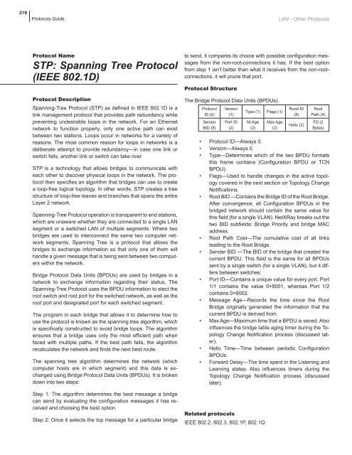
219Protocols GuideLAN - Other ProtocolsProtocol NameSTP: Spanning Tree Protocol(IEEE 802.1D)Protocol DescriptionSpanning-Tree Protocol (STP) as defined in IEEE 802.1D is alink management protocol that provides path redundancy whilepreventing undesirable loops in the <strong>network</strong>. For an Ethernet<strong>network</strong> to function properly, only one active path can existbetween two stations. Loops occur in <strong>network</strong>s for a variety ofreasons. The most common reason for loops in <strong>network</strong>s is adeliberate attempt to provide redundancy—in case one link orswitch fails, another link or switch can take over.STP is a technology that allows bridges to communicate witheach other to discover physical loops in the <strong>network</strong>. The protocolthen specifies an algorithm that bridges can use to createa loop-free logical topology. In other words, STP creates a treestructure of loop-free leaves and branches that spans the entireLayer 2 <strong>network</strong>.Spanning-Tree Protocol operation is transparent to end stations,which are unaware whether they are connected to a single LANsegment or a switched LAN of multiple segments. Where twobridges are used to interconnect the same two computer <strong>network</strong>segments, Spanning Tree is a protocol that allows thebridges to exchange information so that only one of them willhandle a given message that is being sent between two computerswithin the <strong>network</strong>.Bridge Protocol Data Units (BPDUs) are used by bridges in a<strong>network</strong> to exchange information regarding their status. TheSpanning-Tree Protocol uses the BPDU information to elect theroot switch and root port for the switched <strong>network</strong>, as well as theroot port and designated port for each switched segment.The program in each bridge that allows it to determine how touse the protocol is known as the spanning tree algorithm, whichis specifically constructed to avoid bridge loops. The algorithmensures that a bridge uses only the most efficient path whenfaced with multiple paths. If the best path fails, the algorithmrecalculates the <strong>network</strong> and finds the next best route.The spanning tree algorithm determines the <strong>network</strong> (whichcomputer hosts are in which segment) and this data is exchangedusing Bridge Protocol Data Units (BPDUs). It is brokendown into two steps:Step 1: The algorithm determines the best message a bridgecan send by evaluating the configuration messages it has receivedand choosing the best option.Step 2: Once it selects the top message for a particular bridgeto send, it compares its choice with possible configuration messagesfrom the non-root-connections it has. If the best optionfrom step 1 isn’t better than what it receives from the non-rootconnections,it will prune that port.Protocol StructureThe Bridge Protocol Data Units (BPDUs).ProtocolID (2)SenderBID (8)Version(1)Port ID(2)Type (1) Flags (1)M-Age(2)Max Age(2)Rood ID(8)Hello (2)RootPath (4)FD (2Bytes)• Protocol ID—Always 0.• Version—Always 0.• Type—Determines which of the two BPDU formatsthis frame contains (Configuration BPDU or TCNBPDU).• Flags—Used to handle changes in the active topologycovered in the next section on Topology ChangeNotifications.• Root BID —Contains the Bridge ID of the Root Bridge.After convergence, all Configuration BPDUs in thebridged <strong>network</strong> should contain the same value forthis field (for a single VLAN). NetXRay breaks out thetwo BID subfields: Bridge Priority and bridge MACaddress.• Root Path Cost—The cumulative cost of all linksleading to the Root Bridge.• Sender BID —The BID of the bridge that created thecurrent BPDU. This field is the same for all BPDUssent by a single switch (for a single VLAN), but it differsbetween switches.• Port ID—Contains a unique value for every port. Port1/1 contains the value 0×8001, whereas Port 1/2contains 0×8002.• Message Age—Records the time since the RootBridge originally generated the information that thecurrent BPDU is derived from.• Max Age—Maximum time that a BPDU is saved. Alsoinfluences the bridge table aging timer during the TopologyChange Notification process (discussed later).• Hello Time—Time between periodic ConfigurationBPDUs.• Forward Delay—The time spent in the Listening andLearning states. Also influences timers during theTopology Change Notification process (discussedlater).Related <strong>protocols</strong>IEEE 802.2, 802.3, 802.1P, 802.1Q