881 and 881CT Cam Track Hydraulic Benders
881 and 881CT Cam Track® Hydraulic Benders - CableOrganizer.com
881 and 881CT Cam Track® Hydraulic Benders - CableOrganizer.com
- No tags were found...

You also want an ePaper? Increase the reach of your titles
YUMPU automatically turns print PDFs into web optimized ePapers that Google loves.
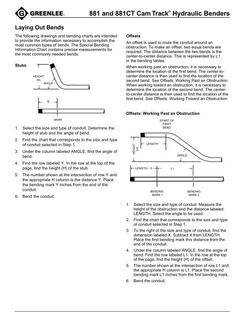
←<strong>881</strong> <strong>and</strong> <strong>881</strong>CT <strong>Cam</strong> <strong>Track</strong> ® <strong>Hydraulic</strong> <strong>Benders</strong>Laying Out BendsThe following drawings <strong>and</strong> bending charts are intendedto provide the information necessary to accomplish themost common types of bends. The Special BendingInformation Chart contains precise measurements forthe most commonly needed bends.Stubs←HEIGHT(H)ANGLE←←←Y →OffsetsAn offset is used to route the conduit around anobstruction. To make an offset, two equal bends arerequired. The distance between the two bends is thecenter-to-center distance. This is represented by L1in the bending tables.When working past an obstruction, it is necessary todetermine the location of the first bend. The center-tocenterdistance is then used to find the location of thesecond bend. See Offsets: Working Past an Obstruction.When working toward an obstruction, it is necessary todetermine the location of the second bend. The centerto-centerdistance is then used to find the location of thefirst bend. See Offsets: Working Toward an Obstruction.←MARK1. Select the size <strong>and</strong> type of conduit. Determine theheight of stub <strong>and</strong> the angle of bend.2. Find the chart that corresponds to the size <strong>and</strong> typeof conduit selected in Step 1.3. Under the column labeled ANGLE, find the angle ofbend.4. Find the row labeled Y. In the row at the top of thepage, find the height (H) of the stub.5. The number shown at the intersection of row Y <strong>and</strong>the appropriate H column is the distance Y. Placethe bending mark Y inches from the end of theconduit.6. Bend the conduit.Offsets: Working Past an Obstruction→← HEIGHT(H)← LENGTHSTART OFFIRSTBEND→→ANGLE→← LENGTH – X → ← L1 →BENDINGMARK 1BENDINGMARK 21. Select the size <strong>and</strong> type of conduit. Measure theheight of the obstruction <strong>and</strong> the distance labeledLENGTH. Select the angle to be used.2. Find the chart that corresponds to the size <strong>and</strong> typeof conduit selected in Step 1.3. To the right of the size <strong>and</strong> type of conduit, find thedimension labeled X. Subtract X from LENGTH.Place the first bending mark this distance from theend of the conduit.4. Under the column labeled ANGLE, find the angle ofbend. Find the row labeled L1. In the row at the topof the page, find the height (H) of the offset.5. The number shown at the intersection of row L1 <strong>and</strong>the appropriate H column is L1. Place the secondbending mark L1 inches from the first bending mark.6. Bend the conduit.