881 and 881CT Cam Track Hydraulic Benders
881 and 881CT Cam Track® Hydraulic Benders - CableOrganizer.com
881 and 881CT Cam Track® Hydraulic Benders - CableOrganizer.com
- No tags were found...

Create successful ePaper yourself
Turn your PDF publications into a flip-book with our unique Google optimized e-Paper software.
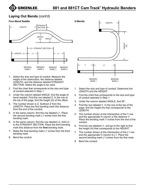
<strong>881</strong> <strong>and</strong> <strong>881</strong>CT <strong>Cam</strong> <strong>Track</strong> ® <strong>Hydraulic</strong> <strong>Benders</strong>Laying Out Bends (cont’d)Four-Bend Saddle← LENGTH →STRAIGHTSECTION←U-Bends← LENGTH →← →HEIGHT→(H) ANGLE→→← LENGTH – Z → ← L1 →←L2 + STRAIGHT SECTION→← L1 →← HEIGHT(H)BENDINGMARK 1BENDINGMARK 2BENDINGMARK 3BENDINGMARK 4← Y → ← L1 →1. Select the size <strong>and</strong> type of conduit. Measure theheight of the obstruction, the distance labeledLENGTH, <strong>and</strong> the distance labeled STRAIGHTSECTION. Select the angle to be used.2. Find the chart that corresponds to the size <strong>and</strong> typeof conduit selected in Step 1.3. Under the column labeled ANGLE, find the angle ofbend needed. Find the row labeled Z. In the row atthe top of the page, find the height (H) of the offset.4. The number shown is Z. Subtract Z from theLENGTH. Place the first bending mark this distancefrom the end of the conduit.5. In the same column, find the row labeled L1. Placethe second bending mark L1 inches from the firstbending mark.6. In the same column, find the row labeled L2. Add L2to the STRAIGHT SECTION. Place the third bendingmark this distance from the first bending mark.7. Make the final bending mark L1 inches from the thirdbending mark.8. Bend the conduit.BENDINGMARK 1BENDINGMARK 21. Select the size <strong>and</strong> type of conduit. Determine theLENGTH <strong>and</strong> the HEIGHT.2. Find the chart that corresponds to the size <strong>and</strong> typeof conduit selected in Step 1.3. Under the column labeled ANGLE, find 90°.4. Find the row labeled Y. In the row at the top of thepage, find the height (H) that corresponds to theLENGTH.5. The number shown at the intersection of the Y row<strong>and</strong> the appropriate H column is the distance Y.Place the bending mark Y inches from the end of theconduit.6. Find the row labeled L1, <strong>and</strong> go to the right to findthe height (H) that corresponds to the HEIGHT.7. The number shown at the intersection of the L1 row<strong>and</strong> the appropriate H column is L1. Place thesecond bending mark L1 inches from the first mark.8. Bend the conduit.