881 and 881CT Cam Track Hydraulic Benders
881 and 881CT Cam Track® Hydraulic Benders - CableOrganizer.com
881 and 881CT Cam Track® Hydraulic Benders - CableOrganizer.com
- No tags were found...

You also want an ePaper? Increase the reach of your titles
YUMPU automatically turns print PDFs into web optimized ePapers that Google loves.
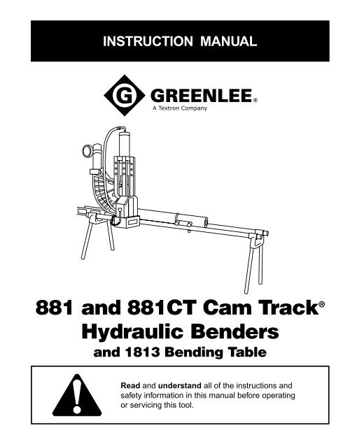
INSTRUCTION MANUAL<strong>881</strong> <strong>and</strong> <strong>881</strong>CT <strong>Cam</strong> <strong>Track</strong> ®<strong>Hydraulic</strong> <strong>Benders</strong><strong>and</strong> 1813 Bending TableRead <strong>and</strong> underst<strong>and</strong> all of the instructions <strong>and</strong>safety information in this manual before operatingor servicing this tool.
<strong>881</strong> <strong>and</strong> <strong>881</strong>CT <strong>Cam</strong> <strong>Track</strong> ® <strong>Hydraulic</strong> <strong>Benders</strong>Table of ContentsDescription ..................................................................... 2Safety ............................................................................. 2Purpose of this Manual .................................................. 2Important Safety Instructions ...................................... 3-4Identification—Major Components,<strong>881</strong> <strong>and</strong> <strong>881</strong>CT Bender ............................................. 5Assembly <strong>and</strong> Operation Instructions .......................6-21<strong>881</strong> <strong>and</strong> <strong>881</strong>CT—Floor Operation .......................... 6-9Identification—Major Components,1813 Bending Table ............................................ 10<strong>881</strong> <strong>and</strong> <strong>881</strong>CT with 1813 Bending Table ..........11-21Glossary of Bending Terms with Illustrations .............. 22Laying Out One-Shot 90° Bends ................................. 23Table 2—Deduct, Stub Dimensions,Minimum Distance from End of Conduit ............. 23Table 3—Ram Travel .............................................. 24Laying Out Two-Shot 90° Bends for 3-1/2" <strong>and</strong> 4"Conduit (<strong>881</strong> only) ................................................... 25Laying Out Bends ...................................................26-28Stubs........................................................................ 26Offsets ................................................................26-27Saddles ...............................................................27-28U-Bends ................................................................... 28Special Bending Information Chart .........................29-32Troubleshooting ......................................................33-34Identification—Major Components,<strong>881</strong> <strong>and</strong> <strong>881</strong>CT Bender ........................................... 35Parts List—<strong>881</strong> <strong>and</strong> <strong>881</strong>CT ......................................... 36Shoe Groups ...........................................................37-39Exploded View—Ram .................................................. 40Parts List—Ram ........................................................... 41Exploded View—1813 Bending Table ......................... 42Parts List—1813 Bending Table .............................43-44DescriptionThe <strong>881</strong> <strong>and</strong> <strong>881</strong>CT <strong>Cam</strong> <strong>Track</strong> ® <strong>Hydraulic</strong> <strong>Benders</strong>are intended to bend rigid conduit, IMC (intermediatemetallic conduit), EMT (electrical metallic conduit) <strong>and</strong>Schedule 40 pipe. Bending shoes, follow bars <strong>and</strong>saddles are available for bending 2-1/2" through 4"conduit or pipe.The bender is to be coupled to any Greenlee hydraulicpump capable of developing 10,000 psi with a usable oilvolume of 6 quarts or more. Suggested pumps includethe following models:Electric Pump (120 volt) ................................. 960 SAPS980Electric Pump (220 Volt) ................................ 980-22FS980-22PSSafetySafety is essential in the use <strong>and</strong> maintenance ofGreenlee tools <strong>and</strong> equipment. This instruction manual<strong>and</strong> any decals on the tool provide information foravoiding hazards <strong>and</strong> unsafe practices related to theuse of this tool. Observe all of the safety informationprovided.Purpose of this ManualThis instruction manual is intended to familiarize operators<strong>and</strong> maintenance personnel with the safe operation<strong>and</strong> maintenance procedures for the Greenlee:<strong>881</strong> <strong>and</strong> <strong>881</strong>CT <strong>Cam</strong> <strong>Track</strong> ® <strong>Hydraulic</strong> <strong>Benders</strong>Keep this manual available to all personnel.Replacement manuals are available upon request at nocharge.All specifications are nominal <strong>and</strong> may change as design improvementsoccur. Greenlee Textron shall not be liable for damagesresulting from misapplication or misuse of its products.<strong>Cam</strong> <strong>Track</strong> is a registered trademark of Greenlee Textron.KEEP THIS MANUAL
<strong>881</strong> <strong>and</strong> <strong>881</strong>CT <strong>Cam</strong> <strong>Track</strong> ® <strong>Hydraulic</strong> <strong>Benders</strong>IMPORTANT SAFETY INFORMATIONSAFETYALERTSYMBOLThis symbol is used to call your attention to hazardsor unsafe practices which could result in an injury orproperty damage. The signal word, defined below,indicates the severity of the hazard. The messageafter the signal word provides information forpreventing or avoiding the hazard.Immediate hazards which, if not avoided, WILLresult in severe injury or death.Read <strong>and</strong> underst<strong>and</strong> all of theinstructions <strong>and</strong> safety informationin this manual before operating orservicing this tool.Failure to observe this warning canresult in severe injury or death.Use only Greenlee shoes <strong>and</strong> components whenoperating this bender. Other manufacturers’ shoes<strong>and</strong> components may fail during operation,propelling broken parts with great force.Failure to observe this warning can result insevere injury or death.Hazards which, if not avoided, COULD result insevere injury or death.Hazards or unsafe practices which, if not avoided,MAY result in injury or property damage.
<strong>881</strong> <strong>and</strong> <strong>881</strong>CT <strong>Cam</strong> <strong>Track</strong> ® <strong>Hydraulic</strong> <strong>Benders</strong>IMPORTANT SAFETY INFORMATIONPinch points.Keep h<strong>and</strong>s away from bendingshoe, follow bar, saddle, conduit,<strong>and</strong> other moving parts whenbender is in use. Failure to keeph<strong>and</strong>s away from these areas canresult in serious injury.Do not st<strong>and</strong> in direct line with the follow bar.A component failure could propel the follow barwith great force, striking nearby personnel.Failure to observe this warning could result insevere injury or death.Wear eye protection when operatingthe bender.Failure to wear eye protection canresult in serious eye injury fromflying debris or hydraulic oil.Inspect the bender, pump, <strong>and</strong> hose before eachuse. Replace damaged, worn, or missing parts withGreenlee replacement parts; a damaged or worncomponent may fail <strong>and</strong> strike nearby personnel.Do not operate while wearing loose clothing.Loose clothing could get caught in moving parts.Failure to observe this warning could result insevere injury.Some bender parts <strong>and</strong> accessories are heavy <strong>and</strong>require more than one person to lift <strong>and</strong> assemble.Failure to observe this precaution could result ininjury or property damage.Do not st<strong>and</strong> in direct line with the hydraulic ram.A component failure could propel parts with greatforce, striking nearby personnel.Failure to observe this warning could result insevere injury or death.Make sure all hose fittings are properly seatedbefore starting the bend. Incomplete connectionsmay not allow the ram to retract after the bend iscomplete.Follow the instructions <strong>and</strong> safety informationsupplied with your hydraulic pump.
Identification—Major Components<strong>881</strong> <strong>and</strong> <strong>881</strong>CT <strong>Cam</strong> <strong>Track</strong> ® <strong>Hydraulic</strong> <strong>Benders</strong>RAM (A)YOKE PIN (G)CYLINDER BLOCK PIN UNIT (F)CONNECTING BAR UNIT (C)SPRING CLIP (H)YOKE (B)EEEROLLER UNIT (D)HITCH PIN CLIPS (E)SADDLE PIN UNIT (M)SHOEFOLLOW BARSADDLE
Assembly <strong>and</strong> Operation Instructions<strong>881</strong> <strong>and</strong> <strong>881</strong>CT <strong>Cam</strong> <strong>Track</strong> ® <strong>Hydraulic</strong> <strong>Benders</strong><strong>881</strong> <strong>and</strong> <strong>881</strong>CT—Floor Operation (refer to Identification—Major Components)1. Lay out the connecting bars (C), roller unit (D), <strong>and</strong>two hitch pin clips (E).RAM TRAVELSCALECONNECTING BARWITH BENDINGINSTRUCTIONS DECALS4. Position the ram <strong>and</strong> cylinder block so that, from theoperator’s point of view, the ram scale is up <strong>and</strong> tothe left of the ram.2. Attach the roller unit to one of the connecting barswith a hitch pin clip, as shown.DECALSFACE OUTWARD5. Attach the yoke (B) to the ram with the spring clip (H).3. Repeat Step 2 for the other connecting bar.
Assembly <strong>and</strong> Operation Instructions<strong>881</strong> <strong>and</strong> <strong>881</strong>CT—Floor Operation (cont’d)<strong>881</strong> <strong>and</strong> <strong>881</strong>CT <strong>Cam</strong> <strong>Track</strong> ® <strong>Hydraulic</strong> <strong>Benders</strong>6. Select the shoe for the size of conduit to be bent.Insert the shoe with the shoe size marking facing up.Align either the EMT or Rigid/IMC hole with the yoke<strong>and</strong> insert the yoke pin (G). Secure the yoke pin witha hitch pin clip (E).8. Lift the connecting bar <strong>and</strong> insert the follow bar.Note: Insert the end marked START.9. Reinsert the hitch pin clip into the roller shaft.7. Remove one hitch pin clip from the roller shaft.
Assembly <strong>and</strong> Operation Instructions<strong>881</strong> <strong>and</strong> <strong>881</strong>CT—Floor Operation (cont’d)<strong>881</strong> <strong>and</strong> <strong>881</strong>CT <strong>Cam</strong> <strong>Track</strong> ® <strong>Hydraulic</strong> <strong>Benders</strong>Follow the instructions <strong>and</strong> safety informationsupplied with your hydraulic pump.The instructions provided here apply to Greenlee960 (shown in the illustrations) <strong>and</strong> 980 (not shown)hydraulic pumps only.10. Attach the hose (L) to the pump <strong>and</strong> ram.BENDING MARKSADDLE INSERTSADDLE11. Make sure the shoe <strong>and</strong> follow bar grooves areclean. Insert the conduit into the bender.13. Rotate the pump control lever counterclockwise.Activate the hydraulic pump until the shoe justcontacts the conduit. Check that the saddle <strong>and</strong>follow bar are snug. Be sure that the follow barcontacts the saddle. Be sure that the bending markon the conduit is aligned with the front edge of thesaddle insert. Calibrate the bender (see Calibratethe Bender Before Bending under Table 3—RamTravel).Activate the hydraulic pump to begin the bend.12. Set the conduit into the groove of the shoe. Rotatethe shoe as necessary to align the saddle with theshoe. Position the saddle so the saddle insert istoward the operator, as shown. Attach the saddle tothe shoe with the saddle pin unit (M); secure the pinunit with the hitch pin clip (E).Note: Align the bending mark on the conduit withthe outside edge of the saddle insert.14. 10° of bend.
Assembly <strong>and</strong> Operation Instructions<strong>881</strong> <strong>and</strong> <strong>881</strong>CT—Floor Operation (cont’d)<strong>881</strong> <strong>and</strong> <strong>881</strong>CT <strong>Cam</strong> <strong>Track</strong> ® <strong>Hydraulic</strong> <strong>Benders</strong>15. 45° of bend.18. Release the hydraulic pressure. The ram will retract.16. 60° of bend.19. Remove the saddle pin.17. 90° of bend.20. The 90° bend is complete.
Identification—Major Components<strong>881</strong> <strong>and</strong> <strong>881</strong>CT <strong>Cam</strong> <strong>Track</strong> ® <strong>Hydraulic</strong> Bender <strong>and</strong> 1813 Bending Table<strong>881</strong> <strong>and</strong> <strong>881</strong>CT <strong>Cam</strong> <strong>Track</strong> ® <strong>Hydraulic</strong> <strong>Benders</strong>RAM (A)YOKE PIN (G)CYLINDER BLOCK PIN UNIT (F)CONNECTING BAR UNIT (C)SPRING CLIP (H)YOKE (B)EEEROLLER UNIT (D)HITCH PIN CLIPS (E)SADDLE PIN UNIT (M)SHOEFOLLOW BARSADDLERAM POSITIONER (33) PIPE VISE UNIT (38) LEG SUPPORT UNIT (23)PIPE CLAMP (34)PUMP TABLE SUPPORT (26)BENDER MOUNTING UNIT (27)LEG (25)
Assembly <strong>and</strong> Operation Instructions<strong>881</strong> <strong>and</strong> <strong>881</strong>CT <strong>Cam</strong> <strong>Track</strong> ® <strong>Hydraulic</strong> <strong>Benders</strong><strong>881</strong> <strong>and</strong> <strong>881</strong>CT with 1813 Bending Table (refer to Identification—Major Components)1. Lay out the connecting bars (C), roller unit (D), <strong>and</strong>two hitch pin clips (E).CONNECTING BARWITH BENDINGINSTRUCTIONS DECALS4. Insert 29" leg (25) into leg support unit (23). Tightenthe cap screw (24). Repeat for the other three legs.2. Attach the roller unit to one of the connecting barswith a hitch pin clip, as shown.5. Insert two 10-foot lengths of IMC or rigid conduit intothe leg support unit (23). Tighten four cap screws (24).Note: These lengths of conduit are not furnishedwith the 1813 Bending Table.DECALSFACE OUTWARDTABS3. Repeat Step 2 for the other connecting bar.6. Position the bender mounting unit (27) as shown,<strong>and</strong> slide it, tabs first, onto the two 10-foot conduits.
Assembly <strong>and</strong> Operation Instructions<strong>881</strong> <strong>and</strong> <strong>881</strong>CT with 1813 Bending Table (cont’d)<strong>881</strong> <strong>and</strong> <strong>881</strong>CT <strong>Cam</strong> <strong>Track</strong> ® <strong>Hydraulic</strong> <strong>Benders</strong>15"9. Attach the second leg support unit (23) to the10-foot conduits. Tighten the four screws (24).7. Position the bender mounting unit 15" from theleg support unit. Tighten the two bender mountingunit screws (28).5"12"PIPE CLAMPPUMP SUPPORTUNIT10. Hang the two pipe clamps (34) over each of the10-foot conduits. Set the pipe clamps 5" <strong>and</strong> 12"from the bender mounting unit. Mount the pumpsupports (26) onto the clamps. Do not tightenthe clamps.8. Slide the pipe vise unit (38) onto the two 10-footconduits, as shown.
Assembly <strong>and</strong> Operation Instructions<strong>881</strong> <strong>and</strong> <strong>881</strong>CT with 1813 Bending Table (cont’d)<strong>881</strong> <strong>and</strong> <strong>881</strong>CT <strong>Cam</strong> <strong>Track</strong> ® <strong>Hydraulic</strong> <strong>Benders</strong>14. Slide the pump onto the pump supports. Tighten thescrews on the lower sides of the pump brackets tosecure the pump. Verify that the pump supports are5" <strong>and</strong> 12" from the bender mounting unit. Tightenthe pipe clamp screws.11 <strong>and</strong> 12. Level the table at both ends.PUMPRESERVOIRPUMPBRACKET15 <strong>and</strong> 16. Load the connecting bar <strong>and</strong> roller unitinto the bender mounting unit.13. Remove the rubber feet/casters from the pump.Attach the pump bracket (64) to the pump with thepump bracket mounting hardware (40-43). Seeillustration.
Assembly <strong>and</strong> Operation Instructions<strong>881</strong> <strong>and</strong> <strong>881</strong>CT with 1813 Bending Table (cont’d)<strong>881</strong> <strong>and</strong> <strong>881</strong>CT <strong>Cam</strong> <strong>Track</strong> ® <strong>Hydraulic</strong> <strong>Benders</strong>START17. Insert the follow bar into the bender with the endmarked START, as shown.19 <strong>and</strong> 20. Insert the ram positioner (33).18. Support the rear of the follow bar on the pipevise unit.21. Attach the hydraulic fitting unit (29) to the ram, <strong>and</strong>connect the hose to the fitting unit. Set the cylinder<strong>and</strong> yoke unit on the follow bar. Rotate the pumpcontrol lever counterclockwise.
Assembly <strong>and</strong> Operation Instructions<strong>881</strong> <strong>and</strong> <strong>881</strong>CT with 1813 Bending Table (cont’d)<strong>881</strong> <strong>and</strong> <strong>881</strong>CT <strong>Cam</strong> <strong>Track</strong> ® <strong>Hydraulic</strong> <strong>Benders</strong>22. Activate the hydraulic pump to extend the ramapproximately 14 inches. DO NOT OVER EXTEND.Attach the yoke to the ram positioner with the yokepin (G). Secure the yoke pin with a hitch pin clip (E).23. Insert one cylinder block pin (F) into the hole marked3" CONDUIT as shown.24 <strong>and</strong> 25. Swing the ram unit into position.
Assembly <strong>and</strong> Operation Instructions<strong>881</strong> <strong>and</strong> <strong>881</strong>CT with 1813 Bending Table (cont’d)<strong>881</strong> <strong>and</strong> <strong>881</strong>CT <strong>Cam</strong> <strong>Track</strong> ® <strong>Hydraulic</strong> <strong>Benders</strong>26. Remove the cylinder block pin from the 3 inchconduit hole in the connecting bar. Rotate the pumpcontrol lever clockwise to retract the ram. Positionthe cylinder block at the proper location for the sizeof conduit to be bent. Insert the two cylinder blockpins (F) through the connecting bars <strong>and</strong> through thecylinder block. Secure the pins with two hitch pinclips (E).28. Remove the ram positioner from the connectingbar unit.SADDLE PIN29. Load the shoe into the bender with the saddle pinhole to the left, as shown.27. Remove the yoke pin from the ram positioner.
Assembly <strong>and</strong> Operation Instructions<strong>881</strong> <strong>and</strong> <strong>881</strong>CT with 1813 Bending Table (cont’d)<strong>881</strong> <strong>and</strong> <strong>881</strong>CT <strong>Cam</strong> <strong>Track</strong> ® <strong>Hydraulic</strong> <strong>Benders</strong>30. Rotate the pump control lever counterclockwise.Activate the hydraulic pump to advance the shoeuntil the yoke is aligned with the proper shoe yokepin hole (EMT or IMC/Rigid).33. Remove the vise unit from its position below thefollow bar. Slide the vise unit to the far end of thebending table.31. Attach the yoke to the shoe with the yoke pin (G).Secure the yoke pin with a hitch pin clip (E).34. Insert the conduit to be bent. Rotate the pumpcontrol lever counterclockwise <strong>and</strong> advance theshoe until it nearly contacts the conduit.32. Rotate the pump control lever clockwise to retractthe ram.
Assembly <strong>and</strong> Operation Instructions<strong>881</strong> <strong>and</strong> <strong>881</strong>CT with 1813 Bending Table (cont’d)<strong>881</strong> <strong>and</strong> <strong>881</strong>CT <strong>Cam</strong> <strong>Track</strong> ® <strong>Hydraulic</strong> <strong>Benders</strong>35. Position the vise unit at a distance from the pumpsupport so that the vise unit will not contact thepump support before the bend is complete. Clampthe conduit down in the vise unit.38. Hold the shoe against the conduit <strong>and</strong> position thesaddle so the saddle insert is toward the operator.Align the hole in the saddle with the hole in the shoe<strong>and</strong> insert the saddle pin (M). Secure the saddle pinwith the hitch pin clip (E).SADDLESADDLE INSERTSADDLE39. Allow the bender to rock forward <strong>and</strong> ensure that thefollow bar comes forward with it, so that the followbar contacts the saddle.PINFollow the instructions <strong>and</strong> safety informationsupplied with your hydraulic pump.36. Push the follow bar back (to the right in the illustration)until the follow bar foot contacts the bendermounting unit. Position the saddle <strong>and</strong> saddle pin(M) where they can be reached for assembly.ALIGN BENDING MARK WITHFRONT EDGE OF SADDLE INSERT37. Rock the bender frame as shown <strong>and</strong> rotate theshoe back for the assembly of the saddle <strong>and</strong> pin.40. Rotate the pump control lever counterclockwise.Activate the hydraulic pump until the shoe justcontacts the conduit. Check that the saddle <strong>and</strong>follow bar are snug, <strong>and</strong> that the follow bar isagainst the saddle, as shown. Be sure that thebending mark on the conduit is aligned with the frontedge of the saddle insert. Attach the model 1805Bending Degree Indicator (35) to the conduit. Zerothe indicator by rotating the degree wheel.
Assembly <strong>and</strong> Operation Instructions<strong>881</strong> <strong>and</strong> <strong>881</strong>CT with 1813 Bending Table (cont’d)<strong>881</strong> <strong>and</strong> <strong>881</strong>CT <strong>Cam</strong> <strong>Track</strong> ® <strong>Hydraulic</strong> <strong>Benders</strong>41. Activate the hydraulic pump to begin the bend.44. 45° of bend.42. 15° of bend.45. 60° of bend.43. 30° of bend.46. 75° of bend.
Assembly <strong>and</strong> Operation Instructions<strong>881</strong> <strong>and</strong> <strong>881</strong>CT with 1813 Bending Table (cont’d)<strong>881</strong> <strong>and</strong> <strong>881</strong>CT <strong>Cam</strong> <strong>Track</strong> ® <strong>Hydraulic</strong> <strong>Benders</strong>47. 90° of bend.50. Push the follow bar back to the start position.48. Remove the 1805 Bending Degree Indicator.51. Remove the saddle pin <strong>and</strong> saddle.49. Rotate the pump control lever clockwise to retractthe shoe.52. Release the vise chain.
Assembly <strong>and</strong> Operation Instructions<strong>881</strong> <strong>and</strong> <strong>881</strong>CT with 1813 Bending Table (cont’d)<strong>881</strong> <strong>and</strong> <strong>881</strong>CT <strong>Cam</strong> <strong>Track</strong> ® <strong>Hydraulic</strong> <strong>Benders</strong>53. Remove the conduit from the bender.58. To change the follow bar, twist <strong>and</strong> remove.54 <strong>and</strong> 55. The 90° bend is complete.
Glossary of Bending Terms with Illustrations<strong>881</strong> <strong>and</strong> <strong>881</strong>CT <strong>Cam</strong> <strong>Track</strong> ® <strong>Hydraulic</strong> <strong>Benders</strong>1. amount of offset—the distancethat the conduit or pipe must bere-routed to avoid an obstruction;see offset in this glossary <strong>and</strong>Offsets in Laying Out Bends in thismanual2. back-to-back bend—any U-shapedbend formed by two parallel90-degree bends with a straightsection of conduit or pipe betweenthe bends3. center-to-center distance—thedistance between the successivebends that make up an offset or athree-bend saddle4. depth of offset—same as amount ofoffset5. height of offset—same as amountof offset6. leg length—the distance from theend of a horizontal section of conduitor pipe to the bend; measured fromthe end to the center line, insideedge, or outside edge of the conduitor pipe.7. 90˚ bend—any bend that changesthe direction of the conduit or pipe by90 degrees8. O. D.—the size of any piece ofconduit or pipe as measured by itsoutside diameter9. offset bend—two bends with thesame degree of bend; used to avoidan obstruction blocking the run of theconduit or pipe10. ram travel—the distance that theram of a hydraulic bender moves toaccomplish a particular bend; inchesof ram travel are proportionate todegrees of bend11. rise—the distance from the end of avertical section of conduit or pipe tothe bend; measured from the end tothe center line, inside edge, oroutside edge of the conduit or pipe12. shot—a single bend13. springback—the amount,measured in degrees, that aconduit or pipe tends to straightenafter being bent14. stub—same as rise15. stub-up—same as rise
Laying Out One-Shot 90° Bends<strong>881</strong> <strong>and</strong> <strong>881</strong>CT <strong>Cam</strong> <strong>Track</strong> ® <strong>Hydraulic</strong> <strong>Benders</strong>1. Measure the length of the required stub.2. Find the Minimum Stub Length on the Table 2:Deduct, Stub Dimensions, <strong>and</strong> Minimum Distancefrom End of Conduit. The stub you require must beequal to or longer than the minimum stub length.3. Measure <strong>and</strong> mark the stub length on the conduit.This is Mark 1.4. Find the Deduct on Table 2. Subtract the Deductfrom Mark 1 <strong>and</strong> make a new mark. This is Mark 2,or the bending mark. Find the Minimum Distancefrom End of Conduit in Table 2; be sure that Mark 2is at least this distance from the end of the conduit.5. Align Mark 2 with the outside edge of the saddle.Bend the conduit—see the instructions underAssembly <strong>and</strong> Operating Instructions.STUB LENGTHTO BOTTOMOF CONDUITSTUBLENGTHDEDUCTMARK 1 MARK 2MARK2Table 2Deduct, Stub Dimensions, Minimum Distance from End of ConduitCONDUIT SIZE 2-1/2 3 3-1/2 4EMTDeduct 21-1/2 24 27-3/4 32-1/4Minimum Stub Length 24 27 31-1/4 36-1/4Minimum Distance from End of Conduit 2-1/2 3 3-1/2 4IMC-RIGIDDeduct 21-1/2 24-1/4 28-1/4 32-1/2Minimum Stub Length 24 26-3/4 30-3/4 35Minimum Distance from End of Conduit 2-1/2 2-1/2 2-1/2 2-1/2
<strong>881</strong> <strong>and</strong> <strong>881</strong>CT <strong>Cam</strong> <strong>Track</strong> ® <strong>Hydraulic</strong> <strong>Benders</strong>Table 3Ram Travel(Figures are approximate)Ram Travel: Read Scale at Edge of BlockNote: Ram Scale Must be Set on ZeroNote: Calibrate Bender Before Bending: Snug upbender by advancing ram until shoe, conduit <strong>and</strong> followbar are snug. (Do not squeeze or begin to bend.) Stoppump. Compare reading on scale with appropriate Snug-Up 0° column on ram travel charts. Note variance if any.Incorporate this variance in ram travel measurementsused for bending the same size <strong>and</strong> type of conduit.DEGREEEMTOFBEND 2-1/2 (90°) 3 (90°) 3-1/2 (90°) 4 (90°) 3-1/2 (45°) 4 (45°)SNUG-UP0° 4-3/16 3-7/8 3-1/8 2-3/8 5 3-9/1610° 5 4-15/16 4-1/8 3-1/4 6-5/8 5-1/815° 5-1/4 5-5/16 4-1/2 3-3/4 7-1/8 5-1/230° 6-3/16 6-5/16 5-1/2 4-13/16 8-13/16 6-3/845° 7-1/8 7-5/16 6-1/2 6 10-1/4 7-3/460° 8 8-3/8 7-1/2 7-1/4 See Table 4 See Table 490° 9-1/2 10-3/8 9-13/16 9-5/8 See Table 4 See Table 4DEGREEIMCOFBEND 2-1/2 (90°) 3 (90°) 3-1/2 (90°) 4 (90°) 3-1/2 (45°) 4 (45°)SNUG-UP0° 2-7/8 2-1/4 2-1/16 1-7/16 5 2-3/810° 4 3-5/8 3-1/8 2-5/8 6-5/8 4-5/1615° 4-7/16 4-1/16 3-9/16 3-1/4 7-1/8 4-15/1630° 5-3/4 5-3/8 5-1/16 4-5/8 8-13/16 6-5/845° 7-3/16 6-15/16 6-7/16 6-1/4 10-1/4 8-1/260° 8-11/16 8-7/16 7-7/8 7-7/8 See Table 4 See Table 490° 11 11-5/8 10-7/8 11-1/8 See Table 4 See Table 4DEGREERIGIDOFBEND 2-1/2 (90°) 3 (90°) 3-1/2 (90°) 4 (90°) 3-1/2 (45°) 4 (45°)SNUG-UP0° 2-7/8 2-1/4 2 1-5/16 4-5/8 2-1/810° 3-15/16 3-5/8 3 2-3/8 6-3/8 4-1/1615° 4-3/8 4-1/16 3-1/2 3 6-13/16 4-3/430° 5-3/4 5-3/8 4-7/8 4-1/2 8-1/2 6-1/245° 7-1/8 6-15/16 6-1/4 6-1/8 10-1/8 8-1/460° 8-1/2 8-7/16 7-3/4 7-3/4 See Table 4 See Table 490° 11 11-5/8 10-3/4 11 See Table 4 See Table 4
Laying Out Two-Shot 90° Bends for3-1/2" <strong>and</strong> 4" Conduit (<strong>881</strong> Only)<strong>881</strong> <strong>and</strong> <strong>881</strong>CT <strong>Cam</strong> <strong>Track</strong> ® <strong>Hydraulic</strong> <strong>Benders</strong>1. Measure the length of the required stub.2. Find the Minimum Stub Length on the Table 2:Deduct, Stub Dimensions, <strong>and</strong> Minimum Distancefrom End of Conduit. The stub you require must beequal to or longer than the minimum stub length.3. Measure <strong>and</strong> mark the stub length on the conduit.This is Mark 14. Find the Deduct on Table 2. Subtract the Deductfrom Mark 1 <strong>and</strong> make a new mark. This is Mark 2,or the first bending mark. Find the Minimum Distancefrom End of Conduit in Table 2; be sure thatMark 2 is at least this distance from the end of theconduit.5. Measure <strong>and</strong> make Mark 3, or the secondbending mark:• For 3-1/2" conduit, Mark 3 must be 14-1/2 inchesfrom Mark 2.• For 4-1/2" conduit, Mark 3 must be 15-1/2 inchesfrom Mark 2.6. See Figure 6: For Making 90° Bends on 3-1/2" <strong>and</strong>4" Conduit. Using the suggested amount of ramtravel, align Mark 2 with the outside edge of thesaddle <strong>and</strong> bend the conduit.7. Align mark 3 with the outside of the saddle.Note: A portion of the previous bend will fall insidethe shoe.8. Bend the conduit until the 90° bend is complete.EMT CONDUIT SIZE 1ST 90°BENDRAM 3-1/2 10-3/16 9-3/4TRAVEL 4 8-3/16 8-3/16IMC CONDUIT SIZE 1ST 90°BENDRAM 3-1/2 11-1/4 10-11/16TRAVEL 4 9 9-1/16RIGID CONDUIT SIZE 1ST 90°BENDRAM 3-1/2 11-1/8 10-1/2TRAVEL 4 8-5/16 8-7/8FIRST BENDSECOND BENDMARK NO. 2 MARK NO. 3STUB LENGTHMARKNO. 3The 45° two-shot shoes <strong>and</strong> follow bars are notinterchangeable with the 90° one-shot shoes<strong>and</strong> follow bars. See Illustration.MARKNO. 1DEDUCTMARKNO. 2THIS SHOEPROFILEMATCHESLONG (OVER 36")FOLLOW BAR WITHSIDE POCKETSTHIS SHOEPROFILEMATCHESSHORT FOLLOW BARWITH SMOOTH SIDES
←<strong>881</strong> <strong>and</strong> <strong>881</strong>CT <strong>Cam</strong> <strong>Track</strong> ® <strong>Hydraulic</strong> <strong>Benders</strong>Laying Out BendsThe following drawings <strong>and</strong> bending charts are intendedto provide the information necessary to accomplish themost common types of bends. The Special BendingInformation Chart contains precise measurements forthe most commonly needed bends.Stubs←HEIGHT(H)ANGLE←←←Y →OffsetsAn offset is used to route the conduit around anobstruction. To make an offset, two equal bends arerequired. The distance between the two bends is thecenter-to-center distance. This is represented by L1in the bending tables.When working past an obstruction, it is necessary todetermine the location of the first bend. The center-tocenterdistance is then used to find the location of thesecond bend. See Offsets: Working Past an Obstruction.When working toward an obstruction, it is necessary todetermine the location of the second bend. The centerto-centerdistance is then used to find the location of thefirst bend. See Offsets: Working Toward an Obstruction.←MARK1. Select the size <strong>and</strong> type of conduit. Determine theheight of stub <strong>and</strong> the angle of bend.2. Find the chart that corresponds to the size <strong>and</strong> typeof conduit selected in Step 1.3. Under the column labeled ANGLE, find the angle ofbend.4. Find the row labeled Y. In the row at the top of thepage, find the height (H) of the stub.5. The number shown at the intersection of row Y <strong>and</strong>the appropriate H column is the distance Y. Placethe bending mark Y inches from the end of theconduit.6. Bend the conduit.Offsets: Working Past an Obstruction→← HEIGHT(H)← LENGTHSTART OFFIRSTBEND→→ANGLE→← LENGTH – X → ← L1 →BENDINGMARK 1BENDINGMARK 21. Select the size <strong>and</strong> type of conduit. Measure theheight of the obstruction <strong>and</strong> the distance labeledLENGTH. Select the angle to be used.2. Find the chart that corresponds to the size <strong>and</strong> typeof conduit selected in Step 1.3. To the right of the size <strong>and</strong> type of conduit, find thedimension labeled X. Subtract X from LENGTH.Place the first bending mark this distance from theend of the conduit.4. Under the column labeled ANGLE, find the angle ofbend. Find the row labeled L1. In the row at the topof the page, find the height (H) of the offset.5. The number shown at the intersection of row L1 <strong>and</strong>the appropriate H column is L1. Place the secondbending mark L1 inches from the first bending mark.6. Bend the conduit.
<strong>881</strong> <strong>and</strong> <strong>881</strong>CT <strong>Cam</strong> <strong>Track</strong> ® <strong>Hydraulic</strong> <strong>Benders</strong>Laying Out Bends (cont’d)Offsets: Working Toward an Obstruction← LENGTH TO END OF SECOND BEND →Three-Bend Saddle← LENGTH TO CENTER →→← HEIGHT(H)→ANGLE→← →HEIGHT (H)→ANGLE→← LENGTH – Z → ← L1 →← LENGTH – Z → ← L1 → ←L2 →BENDINGMARK 1BENDINGMARK 2BENDINGMARK 1BENDINGMARK 2BENDINGMARK 31. Select the size <strong>and</strong> type of conduit. Measure theheight of the obstruction <strong>and</strong> the distance labeledLENGTH TO END OF SECOND BEND. Select theangle to be used.2. Find the chart that corresponds to the size <strong>and</strong> typeof conduit selected in Step 1.3. Under the column labeled ANGLE, find the angle ofbend. Find the row labeled Z. In the row at the top ofthe page, find the height (H) of the offset.4. The number shown at the intersection of the Z row<strong>and</strong> the appropriate H column is Z. Subtract Z fromLENGTH TO THE END OF SECOND BEND. Placethe first bending mark this distance from the end ofthe conduit.5. In the same column, find the row labeled L1. Placethe second bending mark L1 inches from the firstbending mark.6. Bend the conduit.1. Select the size <strong>and</strong> type of conduit. Measure theheight of the obstruction <strong>and</strong> the distance fromthe end of the conduit to the center (LENGTH TOCENTER) of the bend. Select the angle to be used.Note: The second bend angle will be twice thenumber of degrees as the first <strong>and</strong> thirdbends.2. Find the chart that corresponds to the size <strong>and</strong> typeof conduit selected in Step 1.3. Under the column labeled ANGLE, find the angle ofbend needed. Find the row labeled Z. In the row atthe top of the page, find the height (H) of the offset.4. The number shown at the intersection of the Z row<strong>and</strong> the appropriate H column is Z. Subtract Z fromthe LENGTH TO CENTER. Place the first bendingmark this distance from the end of the conduit.5. In the same column, find the row labeled L1. Placethe second bending mark L1 inches from the firstbending mark.6. In the same column, find the row labeled L2. Placethe third bending mark L2 inches from the secondbending mark.7. Bend the conduit.
<strong>881</strong> <strong>and</strong> <strong>881</strong>CT <strong>Cam</strong> <strong>Track</strong> ® <strong>Hydraulic</strong> <strong>Benders</strong>Laying Out Bends (cont’d)Four-Bend Saddle← LENGTH →STRAIGHTSECTION←U-Bends← LENGTH →← →HEIGHT→(H) ANGLE→→← LENGTH – Z → ← L1 →←L2 + STRAIGHT SECTION→← L1 →← HEIGHT(H)BENDINGMARK 1BENDINGMARK 2BENDINGMARK 3BENDINGMARK 4← Y → ← L1 →1. Select the size <strong>and</strong> type of conduit. Measure theheight of the obstruction, the distance labeledLENGTH, <strong>and</strong> the distance labeled STRAIGHTSECTION. Select the angle to be used.2. Find the chart that corresponds to the size <strong>and</strong> typeof conduit selected in Step 1.3. Under the column labeled ANGLE, find the angle ofbend needed. Find the row labeled Z. In the row atthe top of the page, find the height (H) of the offset.4. The number shown is Z. Subtract Z from theLENGTH. Place the first bending mark this distancefrom the end of the conduit.5. In the same column, find the row labeled L1. Placethe second bending mark L1 inches from the firstbending mark.6. In the same column, find the row labeled L2. Add L2to the STRAIGHT SECTION. Place the third bendingmark this distance from the first bending mark.7. Make the final bending mark L1 inches from the thirdbending mark.8. Bend the conduit.BENDINGMARK 1BENDINGMARK 21. Select the size <strong>and</strong> type of conduit. Determine theLENGTH <strong>and</strong> the HEIGHT.2. Find the chart that corresponds to the size <strong>and</strong> typeof conduit selected in Step 1.3. Under the column labeled ANGLE, find 90°.4. Find the row labeled Y. In the row at the top of thepage, find the height (H) that corresponds to theLENGTH.5. The number shown at the intersection of the Y row<strong>and</strong> the appropriate H column is the distance Y.Place the bending mark Y inches from the end of theconduit.6. Find the row labeled L1, <strong>and</strong> go to the right to findthe height (H) that corresponds to the HEIGHT.7. The number shown at the intersection of the L1 row<strong>and</strong> the appropriate H column is L1. Place thesecond bending mark L1 inches from the first mark.8. Bend the conduit.
Special Bending Information Chart<strong>881</strong> <strong>and</strong> <strong>881</strong>CT <strong>Cam</strong> <strong>Track</strong> ® <strong>Hydraulic</strong> <strong>Benders</strong>HEIGHT – HDIM ANGLE 10" 12" 15" 18" 24" 30" 36" 42" 48" 60"2-1/2 EMT Dia. = 2.875 Radius = 13.9 x = 6.15MINIMUM H = 2.54MINIMUM H = 4.47MINIMUM H = 6.80MINIMUM H = 12.49MINIMUM H = 19.23MINIMUM H = 33.95Y 15.00 25.10 32.83 44.42 56.01 79.19 102.38 125.56 148.74 171.92 218.29L1 15.00 38.62 46.34 57.93 69.53 92.71 115.89 139.07 162.25 185.44 231.80L2 15.00 42.26 49.98 61.57 73.16 96.35 119.53 142.71 165.89 189.08 235.44Z 15.00 47.13 54.59 65.79 76.99 99.38 121.77 144.16 166.56 188.95 233.73Y 22.50 13.46 18.69 26.53 34.37 50.04 65.72 81.40 97.08 112.76 144.12L1 22.50 26.06 31.29 39.13 46.97 62.64 78.32 94.00 109.68 125.36 156.72L2 22.50 31.52 36.74 44.58 52.42 68.10 83.78 99.46 115.14 130.82 162.17Z 22.50 35.82 40.65 47.89 55.14 69.62 84.11 98.59 113.08 127.56 156.53Y 30.00 7.25 11.25 17.25 23.25 35.25 47.25 59.25 71.25 83.25 107.25L1 30.00 19.83 23.83 29.83 35.83 47.83 59.83 71.83 83.83 95.83 119.83L2 30.00 27.11 31.11 37.11 43.11 55.11 67.11 79.11 91.11 103.11 127.11Z 30.00 30.92 34.38 39.58 44.78 55.17 65.56 75.95 86.35 96.74 117.52Y 45.00 3.03 7.27 11.52 20.00 28.49 36.97 45.46 53.94 70.91L1 45.00 16.37 20.62 24.86 33.34 41.83 50.31 58.80 67.28 84.25L2 45.00 27.29 31.53 35.77 44.26 52.75 61.23 69.72 78.20 95.17Z 45.00 29.67 32.67 35.67 41.67 47.67 53.67 56.67 65.67 77.67Y 60.00 1.49 4.95 11.88 18.81 25.73 32.66 39.59 53.45L1 60.00 26.22 33.15 40.07 47.00 53.93 67.79L2 60.00 40.77 47.70 54.63 61.56 68.49 82.34Z 60.00 36.06 39.52 42.98 46.45 49.91 56.84Y 90.00 2.51 8.51 14.51 20.51 26.51 38.51L1 90.00 30.03 36.03 42.03 54.03L2 90.00 51.87 57.87 63.87 75.87Z 90.00 33.95 33.95 33.95 33.953 EMT Dia. = 3.5 Radius = 16.48 x = 5.77MINIMUM H = 2.62MINIMUM H = 4.72MINIMUM H = 7.30MINIMUM H = 13.73MINIMUM H = 21.48MINIMUM H = 38.73Y 15.00 23.94 31.66 43.25 54.85 78.03 101.21 124.39 147.57 170.76 217.12L1 15.00 38.61 46.34 57.93 69.52 92.70 115.89 139.07 162.25 185.43 231.80L2 15.00 42.93 50.65 62.25 73.84 97.02 120.20 143.38 166.57 189.75 236.11Z 15.00 47.43 54.89 66.09 77.29 99.68 122.07 144.46 166.86 189.25 234.03Y 22.50 12.51 17.74 25.58 33.42 49.09 64.77 80.45 96.13 111.81 143.17L1 22.50 26.05 31.27 39.11 46.95 62.63 78.31 93.99 109.67 125.35 156.70L2 22.50 32.52 37.74 45.58 53.42 69.10 84.78 100.46 116.14 131.82 163.17Z 22.50 36.47 41.30 48.54 55.78 70.27 84.75 99.24 113.72 128.21 157.18Y 30.00 6.31 10.31 16.31 22.31 34.31 46.31 58.31 70.31 82.31 106.31L1 30.00 19.80 23.80 29.80 35.80 47.80 59.80 71.80 83.80 95.80 119.80L2 30.00 28.43 32.43 38.43 44.43 56.43 68.43 80.43 92.43 104.43 128.43Z 30.00 31.92 35.39 40.58 45.78 56.17 66.56 76.96 87.35 97.74 118.52Y 45.00 1.90 6.14 10.38 18.87 27.36 35.84 44.33 52.81 69.78L1 45.00 20.50 24.75 33.23 41.72 50.20 58.69 67.17 84.14L2 45.00 33.45 37.69 46.18 54.66 63.15 71.63 80.12 97.09Z 45.00 34.42 37.42 43.42 49.42 55.42 61.42 67.42 79.42Y 60.00 0.02 3.48 10.41 17.34 24.26 31.19 38.12 51.98L1 60.00 25.94 32.87 39.80 46.73 53.65 67.51L2 60.00 43.20 50.13 57.06 63.98 70.91 84.77Z 60.00 38.66 42.12 45.58 49.05 52.51 59.44Y 90.00 0.00 6.00 12.00 18.00 24.00 36.00L1 90.00 34.93 40.93 52.93L2 90.00 60.81 66.81 78.81Z 90.00 38.73 38.73 38.73
Special Bending Information Chart (cont’d)<strong>881</strong> <strong>and</strong> <strong>881</strong>CT <strong>Cam</strong> <strong>Track</strong> ® <strong>Hydraulic</strong> <strong>Benders</strong>HEIGHT – HDIM ANGLE 10" 12" 15" 18" 24" 30" 36" 42" 48" 60"3-1/2 EMT Dia. = 4 Radius = 19.18 x = 6.56MINIMUM H = 3.00MINIMUM H = 5.43MINIMUM H = 8.42MINIMUM H = 15.87MINIMUM H = 24.86MINIMUM H = 44.92Y 15.00 21.82 29.55 41.14 52.73 75.92 99.10 122.28 145.46 168.65 215.01L1 15.00 38.61 46.34 57.93 69.52 92.70 115.88 139.06 165.25 185.43 231.79L2 15.00 43.63 51.36 62.95 74.54 97.72 120.90 144.09 167.27 190.45 236.81Z 15.00 48.93 56.39 67.59 78.79 101.18 123.57 145.96 168.36 190.75 235.53Y 22.50 10.53 15.76 23.60 31.43 47.11 62.79 78.47 94.15 109.83 141.19L1 22.50 26.03 31.26 39.10 46.94 62.62 78.30 93.97 109.65 125.33 156.69L2 22.50 33.56 38.79 46.63 54.47 70.15 85.83 101.51 117.18 132.86 164.22Z 22.50 38.33 43.16 50.40 57.65 72.13 86.62 101.10 115.59 130.37 159.04Y 30.00 4.30 8.30 14.30 20.30 32.30 44.30 56.30 68.30 80.30 104.30L1 30.00 19.76 23.76 29.76 35.76 47.76 59.76 71.76 83.76 95.76 119.76L2 30.00 29.81 33.81 39.81 45.81 57.81 69.81 81.81 93.81 105.81 129.81Z 30.00 34.16 37.62 42.82 48.02 58.41 68.80 79.19 89.58 99.98 120.76Y 45.00 3.88 8.12 16.61 25.09 33.58 42.06 50.55 67.52L1 45.00 24.63 33.12 41.60 50.09 58.57 67.06 84.03L2 45.00 39.69 48.18 56.67 65.15 73.64 82.12 99.09Z 45.00 40.45 46.45 52.45 58.45 64.45 70.45 82.45Y 60.00 0.84 7.77 14.7 21.63 28.55 35.48 49.34L1 60.00 32.58 39.51 46.44 53.36 67.22L2 60.00 52.66 59.59 66.52 73.45 87.31Z 60.00 46.03 49.49 52.96 56.42 63.35Y 90.00 2.26 8.26 14.26 20.26 32.26L1 90.00 39.77 51.77L2 90.00 69.90 81.90Z 90.00 44.92 44.924 EMT Dia. = 4.5 Radius = 21.5 x = 8.5MINIMUM H = 3.67MINIMUM H = 6.53MINIMUM H = 10.01MINIMUM H = 18.60MINIMUM H = 28.86MINIMUM H = 51.5Y 15.00 18.61 26.34 37.93 49.52 72.71 95.89 119.07 142.25 165.43 211.80L1 15.00 38.60 46.33 57.92 69.51 92.70 115.88 139.06 162.24 185.43 231.79L2 15.00 44.23 51.96 63.55 75.14 98.33 121.51 144.69 167.87 191.05 237.42Z 15.00 51.48 58.95 70.14 81.34 103.73 126.12 148.51 170.91 193.30 238.08Y 22.50 7.48 12.70 20.54 28.38 44.06 59.74 75.42 91.10 106.77 138.13L1 22.50 26.02 31.25 39.09 46.93 62.60 78.28 93.96 109.64 125.32 156.68L2 22.50 34.46 39.69 47.53 55.37 71.05 86.73 102.41 118.08 133.76 165.12Z 22.50 41.20 46.02 53.27 60.51 74.99 89.48 103.96 118.45 132.94 161.91Y 30.00 1.24 5.24 11.24 17.24 29.24 41.24 53.24 65.24 77.24 101.24L1 30.00 19.74 23.74 29.74 35.74 47.74 59.74 71.74 83.74 95.74 119.74L2 30.00 30.99 34.99 40.99 46.99 58.99 70.99 82.99 94.99 106.99 130.99Z 30.00 37.34 40.81 46.00 51.20 61.59 71.98 82.38 92.77 103.16 123.94Y 45.00 0.63 4.87 13.35 21.84 30.32 38.81 47.29 64.27L1 45.00 33.02 41.50 49.99 58.47 66.96 83.93L2 45.00 49.90 58.39 66.87 75.36 83.84 100.81Z 45.00 50.31 56.31 62.31 68.31 74.31 86.31Y 60.00 4.20 11.13 18.06 24.99 31.91 45.77L1 60.00 32.33 39.26 46.19 53.11 66.97L2 60.00 54.84 61.77 68.70 75.63 89.49Z 60.00 50.65 54.11 57.57 61.04 67.97Y 90.00 3.75 9.75 15.75 27.75L1 90.00 50.77L2 90.00 84.54Z 90.00 51.50
Special Bending Information Chart (cont’d)<strong>881</strong> <strong>and</strong> <strong>881</strong>CT <strong>Cam</strong> <strong>Track</strong> ® <strong>Hydraulic</strong> <strong>Benders</strong>HEIGHT – HDIM ANGLE 10" 12" 15" 18" 24" 30" 36" 42" 48" 60"2-1/2 IMC/RIGID Dia. = 2.875 Radius = 13.9 x = 6.15MINIMUM H = 2.54MINIMUM H = 4.47MINIMUM H = 6.80MINIMUM H = 12.49MINIMUM H = 19.23MINIMUM H = 33.95Y 15.00 25.10 32.83 44.42 56.01 79.19 102.38 125.56 148.74 171.92 218.29L1 15.00 38.62 46.34 57.93 69.53 92.71 115.89 139.07 162.25 185.44 231.8L2 15.00 42.26 49.98 61.57 73.16 96.35 119.53 142.71 165.89 189.08 235.44Z 15.00 47.13 54.59 65.79 76.99 99.38 121.77 144.16 166.56 188.95 233.73Y 22.50 13.46 18.69 26.53 34.37 50.04 65.72 81.40 97.08 112.76 144.12L1 22.50 26.06 31.29 39.13 46.97 62.64 78.32 94.00 109.68 125.36 156.72L2 22.50 31.52 36.74 44.58 52.42 68.10 83.78 99.46 115.14 130.82 162.17Z 22.50 35.82 40.65 47.89 55.14 69.62 84.11 98.59 113.08 127.56 156.53Y 30.00 7.25 11.25 17.25 23.25 35.25 47.25 59.25 71.25 83.25 107.25L1 30.00 19.83 23.83 29.83 35.83 47.83 59.83 71.83 83.83 95.83 119.83L2 30.00 27.11 31.11 37.11 43.11 55.11 67.11 79.11 91.11 103.11 127.11Z 30.00 30.92 34.38 39.58 44.78 55.17 65.56 75.95 86.35 96.74 117.52Y 45.00 0.20 3.03 7.27 11.52 20.00 28.49 36.97 45.46 53.94 70.91L1 45.00 20.62 24.86 33.34 41.83 50.31 58.80 67.28 84.25L2 45.00 31.53 35.77 44.26 52.75 61.23 69.72 78.20 95.17Z 45.00 32.67 35.67 41.67 47.67 53.67 59.67 65.67 77.67Y 60.00 1.49 4.95 11.88 18.81 25.73 32.66 39.59 53.45L1 60.00 26.22 33.15 40.07 47.00 53.93 67.79L2 60.00 40.77 47.70 54.63 61.56 68.49 82.34Z 60.00 36.06 39.52 42.98 46.45 49.91 56.84Y 90.00 2.51 8.51 14.51 20.51 26.51 38.51L1 90.00 30.03 36.03 42.03 54.03L2 90.00 51.87 57.87 63.87 75.87Z 90.00 33.95 33.95 33.95 33.953 IMC/RIGID Dia. = 3.5 Radius = 16.48 x = 6MINIMUM H = 2.68MINIMUM H = 4.81MINIMUM H = 7.42MINIMUM H = 13.90MINIMUM H = 21.68MINIMUM H = 38.96Y 15.00 23.71 31.43 43.02 54.62 77.80 100.98 124.16 147.34 170.53 216.89L1 15.00 38.61 46.34 57.93 69.52 92.70 115.89 139.07 162.25 185.43 231.80L2 15.00 42.93 50.65 62.25 73.84 97.02 120.20 143.38 166.57 189.75 236.11Z 15.00 47.66 55.12 66.32 77.52 99.91 122.30 144.69 167.09 189.48 234.26Y 22.50 12.28 17.51 25.35 33.19 48.86 64.54 80.22 95.90 111.58 142.94L1 22.50 26.05 31.27 39.11 46.95 62.63 78.31 93.99 109.67 125.35 156.70L2 22.50 32.52 37.74 45.58 53.42 69.10 84.78 100.46 116.14 131.82 163.17Z 22.50 36.70 41.53 48.77 56.01 70.50 84.98 99.47 113.95 128.44 157.41Y 30.00 6.08 10.08 16.08 22.08 34.08 46.08 58.08 70.08 82.08 106.08L1 30.00 19.80 23.80 29.80 35.80 47.80 59.80 71.80 83.80 95.80 119.80L2 30.00 28.43 32.43 38.43 44.43 56.43 68.43 80.43 92.43 104.43 128.43Z 30.00 32.15 35.62 40.81 46.01 56.40 66.79 77.19 87.58 97.97 118.75Y 45.00 1.67 5.91 10.15 18.64 27.13 35.61 44.10 52.58 69.55L1 45.00 20.50 24.75 33.23 41.72 50.20 58.69 67.17 84.14L2 45.00 33.45 37.69 46.18 54.66 63.15 71.63 80.12 97.09Z 45.00 34.65 37.65 43.65 49.65 55.65 61.65 67.65 79.65Y 60.00 3.25 10.18 17.11 24.03 30.96 37.89 51.75L1 60.00 25.94 32.87 39.80 46.73 53.65 67.51L2 60.00 43.20 50.13 57.06 63.98 70.91 84.77Z 60.00 38.89 42.35 45.81 49.28 52.74 59.67Y 90.00 5.77 11.77 17.77 23.77 35.77L1 90.00 34.93 40.93 52.93L2 90.00 60.81 66.81 78.81Z 90.00 38.96 38.96 38.96
<strong>881</strong> <strong>and</strong> <strong>881</strong>CT <strong>Cam</strong> <strong>Track</strong> ® <strong>Hydraulic</strong> <strong>Benders</strong>Special Bending Information Chart (cont’d)HEIGHT – HDIM ANGLE 10" 12" 15" 18" 24" 30" 36" 42" 48" 60"3-1/2 IMC/RIGID Dia. = 4 Radius = 19.18 x = 7MINIMUM H = 3.12MINIMUM H = 5.60MINIMUM H = 8.64MINIMUM H = 16.19MINIMUM H = 25.24MINIMUM H = 45.36Y 15.00 21.38 29.11 40.70 52.29 75.48 98.66 121.84 145.02 168.21 214.57L1 15.00 38.61 46.34 57.93 69.52 92.70 115.88 139.06 162.25 185.43 231.79L2 15.00 43.63 51.36 62.95 74.54 97.72 120.90 144.09 167.27 190.45 236.81Z 15.00 49.37 56.83 68.03 79.23 101.62 124.01 146.40 168.80 191.19 235.97Y 22.50 10.09 15.32 23.16 30.99 46.67 62.35 78.03 93.71 109.39 140.75L1 22.50 26.03 31.26 39.10 46.94 62.62 78.30 93.97 109.65 125.33 156.69L2 22.50 33.56 38.79 46.63 54.47 70.15 85.83 101.51 117.18 132.86 164.22Z 22.50 38.77 43.60 50.84 58.09 72.57 87.06 101.54 116.03 130.51 159.48Y 30.00 3.86 7.86 13.86 19.86 31.86 43.86 55.86 67.86 79.86 103.86L1 30.00 19.76 23.76 29.76 35.76 47.76 59.76 71.76 83.76 95.76 119.76L2 30.00 29.91 33.81 39.81 45.81 57.81 69.81 81.81 93.81 105.81 129.81Z 30.00 34.60 38.06 43.26 48.46 58.85 69.24 79.63 90.02 100.42 121.20Y 45.00 3.44 7.68 16.17 24.65 33.14 41.62 50.11 67.08L1 45.00 24.63 33.12 41.60 50.09 58.57 67.06 84.03L2 45.00 39.69 48.18 56.67 65.15 73.64 82.12 99.09Z 45.00 40.89 46.89 52.89 58.89 64.89 70.89 82.89Y 60.00 0.40 7.33 14.26 21.19 28.11 35.04 48.90L1 60.00 32.58 39.51 46.44 53.36 67.22L2 60.00 52.66 59.59 66.52 73.45 87.31Z 60.00 46.47 49.93 53.40 56.86 63.79Y 90.00 1.82 7.82 13.82 19.82 31.82L1 90.00 39.77 51.77L2 90.00 69.90 81.90Z 90.00 45.36 45.364 IMC/RIGID Dia. = 4.5 Radius = 21.5 x = 8.75MINIMUM H = 3.73MINIMUM H = 6.62Y 15.00 18.36 26.09 37.68 49.27 72.46 95.64 118.82 142.00 165.18 211.55L1 15.00 38.60 46.33 57.92 69.51 92.70 115.88 139.06 162.24 185.43 231.79L2 15.00 44.23 51.96 63.55 75.14 98.33 121.51 144.69 167.87 191.05 237.42Z 15.00 51.73 59.20 70.39 81.59 103.98 126.37 148.76 171.16 193.55 238.33Y 22.50 7.23 12.45 20.29 28.13 43.81 59.49 75.17 90.85 106.52 137.88L1 22.50 26.02 31.25 39.09 46.93 62.60 78.28 93.96 109.64 125.32 156.68L2 22.50 34.46 39.69 47.53 55.37 71.05 86.73 102.41 118.08 133.76 165.12Z 22.50 41.45 46.27 53.52 60.76 75.24 89.73 104.21 118.70 133.19 162.16Y 30.00 0.99 4.99 10.99 16.99 28.99 40.99 52.99 64.99 76.99 100.99L1 30.00 23.74 29.74 35.74 47.74 59.74 71.74 83.74 95.74 119.74L2 30.00 34.99 40.99 46.99 58.99 70.99 82.99 94.99 106.99 130.99Z 30.00 41.06 46.25 51.45 61.84 72.23 82.63 93.02 103.41 124.19MINIMUM H = 10.13591MINIMUM H = 18.78MINIMUM H = 29.08MINIMUM H = 51.75Y 45.00 0.38 4.62 13.10 21.59 30.07 38.56 47.04 64.02L1 45.00 33.02 41.50 49.99 58.47 66.96 83.93L2 45.00 49.90 58.39 66.87 75.36 83.84 100.81Z 45.00 50.56 56.56 62.56 68.56 74.56 86.56Y 60.00 3.95 10.88 17.81 24.74 31.66 45.52L1 60.00 32.33 39.26 46.19 53.11 66.97L2 60.00 54.84 61.77 68.70 75.63 89.49Z 60.00 50.90 54.36 57.82 61.29 68.22Y 90.00 3.50 9.50 15.50 27.50L1 90.00 50.77L2 90.00 84.54Z 90.00 51.75
<strong>881</strong> <strong>and</strong> <strong>881</strong>CT <strong>Cam</strong> <strong>Track</strong> ® <strong>Hydraulic</strong> <strong>Benders</strong>TroubleshootingPROBLEM PROBABLE CAUSE PROBABLE REMEDYWrinkling of EMT. Shoe pin in wrong position. Move shoe pin to hole marked EMT.Follow bar in backwards.Contact surfaces between shoe <strong>and</strong>follow bar have debris or damage.Follow bar is not positioned within 1"of saddle at start of bend.Follow bar is not centered on roller atstart of bend.Shoe or follow bar grooves are wornor spread.Roller is not rolling on shaft.High yield strength conduit.Remove follow bar <strong>and</strong> insert endmarked START toward saddle.Clean shoe <strong>and</strong> follow bar. Replaceshoe or follow bar as necessary.Position follow bar according to thebending instructions.Center the follow bar on the roller.Replace shoe or follow bar.Lubricate roller.Use st<strong>and</strong>ard EMT.Side creasing of EMT. Follow bar is not centered on roller at Center the follow bar on the roller.start of bend.Conduit is not level (when bending onthe floor).Contact surfaces between shoe <strong>and</strong>follow bar have debris or damage.Pipe vise unit of 1813 is clamped tooclose to bender.Follow bar groove worn or spread.Level the conduit.Clean shoe <strong>and</strong> follow bar. Replaceshoe or follow bar as necessary.Move the pipe vise unit further fromthe bender.Replace follow bar.Won’t bend EMT. Follow bar is in backwards. Remove follow bar <strong>and</strong> insert endmarked START toward saddle.
<strong>881</strong> <strong>and</strong> <strong>881</strong>CT <strong>Cam</strong> <strong>Track</strong> ® <strong>Hydraulic</strong> <strong>Benders</strong>Troubleshooting (cont’d)PROBLEM PROBABLE CAUSE PROBABLE REMEDYWrinkling of IMC or rigid. Follow bar is in backwards. Remove follow bar <strong>and</strong> insert endmarked START toward saddle.Side creasing of IMC or rigid. Conduit is not level (when bending Level the conduit.on floor).Follow bar not centered on roller atstart of bend.Center the follow bar on the roller.Won’t bend IMC or rigid. Shoe pin in wrong position. Move shoe pin to hole markedIMC/RIGID.Follow bar is in backwards.Remove follow bar <strong>and</strong> insert endmarked START toward saddle.Ram will not advance. Pump does not have enough oil. Add oil. See instructions supplied withthe pump.Pump vent is closed.Hose couplings not fully tightened.Excessive voltage drop from longextension cord.Open the pump vent.Tighten the hose couplings.Use a shorter or heavier extension cord.
Identification—Major Components<strong>881</strong> <strong>and</strong> <strong>881</strong>CT <strong>Cam</strong> <strong>Track</strong> ® <strong>Hydraulic</strong> Bender<strong>881</strong> <strong>and</strong> <strong>881</strong>CT <strong>Cam</strong> <strong>Track</strong> ® <strong>Hydraulic</strong> <strong>Benders</strong>LZAGFMHBEEECDENOPBPAPE2-1/2"Bending GroupPEQRPDPCSB3"Bending GroupSASTUWVBVAX3-1/2"Bending GroupV4"Bending GroupYBYAY
<strong>881</strong> <strong>and</strong> <strong>881</strong>CT <strong>Cam</strong> <strong>Track</strong> ® <strong>Hydraulic</strong> <strong>Benders</strong>Parts List—<strong>881</strong> <strong>and</strong> <strong>881</strong>CTKey Part No. Description QtyA 502 7416.3 Ram, 40-ton (see separate parts list).................... 1B 503 0309.0 Yoke ......................................................................1C 502 6309.9 Connecting bar unit(includes the next three items) .............................. 2502 6628.4 Bushing ................................................................. 2905 2932.4 Screw, cap, 5/16–18 x .750 socket head .............. 4500 2754.9 Decal, warning....................................................... 2D 502 7364.7 Roller unit (includes two Key E) ............................ 1E 905 0302.3 Clip, hitch pin, #8 ................................................... 6F 502 7381.7 Cylinder block pin unit (includes one Key E) ........ 2G 502 6306.4 Pin, yoke, 1.24 x 5.80............................................ 1H 502 6349.8 Clip, spring ............................................................ 1L 501 1289.9 Hose unit, 3/8 x 6' with couplers(includes the following two items) ......................... 1905 0760.6 Hose, hydraulic, 3/8 x 6', 3/8 M NPTF .................. 1905 0823.8 Coupler, quick, 3/8 male ....................................... 2M 502 6624.1 Saddle pin unit (includes the following item)......... 1905 0302.3 Clip, hitch pin, #8 ................................................... 1
Shoe Groups for the <strong>881</strong> <strong>and</strong> <strong>881</strong>CT<strong>881</strong> <strong>and</strong> <strong>881</strong>CT <strong>Cam</strong> <strong>Track</strong> ® <strong>Hydraulic</strong> <strong>Benders</strong>Key Part No. Description Qty502 7554.2 2-1/2" One-shot 90° shoe group(13-1/2" centerline bending radius)N 502 6297.1 2-1/2" Shoe............................................................ 1O 502 6366.8 2-1/2" Follow bar unit(includes the following two items) ......................... 1502 6364.1 Bar, reinforcement, 2-1/2" ..................................... 2905 0226.4 Screw, cap, 5/16–18 x 1.25 socket head .............. 6P 502 6580.6 2-1/2" Saddle (includes PA, PB, PC) .................... 1PA 502 6583.0 2-1/2" Saddle insert ............................................... 1PB 502 6581.4 2-1/2" Saddle strap................................................ 1PC 905 1088.7 Screw, cap ............................................................. 2502 7555.0 3" One-shot 90° shoe group(16" centerline bending radius)PD 905 0028.8 Lock washer .......................................................... 2PE 905 2646.5 Lock nut ................................................................. 2Q 502 6300.5 3" Shoe .................................................................. 1R 503 5400.0 3" Follow bar + ...................................................... 1+ to order both reinforcement bars for thisfollow bar, order the following item:503 5467.1 Conversion kit, 3" reinforcement barS 502 6584.9 3" Saddle (includes SA, SB, PC) .......................... 1SA 502 6587.3 3" Saddle insert ..................................................... 1SB 502 6585.7 3" Saddle strap ...................................................... 1PC 905 1088.7 Screw, cap ............................................................. 2PD 905 0028.8 Lock washer .......................................................... 2PE 905 2646.5 Lock nut ................................................................. 2
Shoe Groups for the <strong>881</strong>CT Only<strong>881</strong> <strong>and</strong> <strong>881</strong>CT <strong>Cam</strong> <strong>Track</strong> ® <strong>Hydraulic</strong> <strong>Benders</strong>Key Part No. Description Qty503 1281.2 3-1/2" One-shot 90° shoe group(18-5/8" centerline bending radius)(includes T, U, V)T 503 1882.9 3-1/2" Shoe............................................................ 1U 503 1278.2 3-1/2" Follow bar (to replace, order 503 1<strong>881</strong>.0) ... 1503 1277.4 Bar, reinforcement 3-1/2" ...................................... 2905 0224.8 Screw, cap, 5/16–18 x 1.00 socket head .............. 4905 0226.4 Screw, cap, 5/16–18 x 1.25 socket head .............. 2V 502 6588.1 3-1/2" Saddle (includes the next two items <strong>and</strong> PC) 1VA 502 6593.8 3-1/2" Saddle insert ............................................... 1VB 502 6590.3 3-1/2" Saddle strap ................................................ 1PC 905 1088.7 Screw, cap ............................................................. 2PD 905 0028.8 Lock washer .......................................................... 2PE 905 2646.5 Lock nut ................................................................. 2503 1274.0 4" One-shot 90° shoe group(20-7/8" centerline bending radius)(includes W, X, Y)W 503 1884.5 4" Shoe .................................................................. 1X 503 1271.5 4" Follow bar (to replace, order 503 1883.7) ........ 1503 1270.7 Bar, reinforcement, 4" ........................................... 2905 0224.8 Screw, cap, 5/16–18 x 1.00 socket head .............. 4905 0226.4 Screw, cap, 5/16–18 x 1.25 socket head .............. 2Y 502 6594.6 4" Saddle (includes the next two items <strong>and</strong> PC) ... 1YA 502 6597.0 4" Saddle insert ..................................................... 1YB 502 6595.4 4" Saddle strap ...................................................... 1PC 905 1088.7 Screw, cap ............................................................. 2PD 905 0028.8 Lock washer .......................................................... 2PE 905 2646.5 Lock nut ................................................................. 2
Shoe Groups for the <strong>881</strong>CT Only<strong>881</strong> <strong>and</strong> <strong>881</strong>CT <strong>Cam</strong> <strong>Track</strong> ® <strong>Hydraulic</strong> <strong>Benders</strong>Key Part No. Description Qty502 7556.9 3-1/2" Shoe group(18-5/8" centerline bending radius)(includes T, U, V)T 502 6302.1 3-1/2" Shoe............................................................ 1U 502 6389.7 3-1/2" Follow bar unit(includes the following two items) ......................... 1502 6392.7 Bar, reinforcement, 3-1/2" ..................................... 2905 0226.4 Screw, cap, 5/16–18 x 1.25 socket head .............. 6502 7557.7 4" Shoe group (21" centerline bending radius)(includes W, X, Y)W 502 6305.6 4" Shoe .................................................................. 1X 503 1292.8 4" Follow bar unit(includes the following two items) ......................... 1503 1293.6 Bar, reinforcement, 4" ........................................... 2905 0226.4 Screw, cap, 5/16–18 x 1.25 socket head .............. 6Z 502 3363.7 Box, job ................................................................. 1503 0239.6 Set, casters (two rigid, two swivel) ........................ 1
<strong>881</strong> <strong>and</strong> <strong>881</strong>CT <strong>Cam</strong> <strong>Track</strong> ® <strong>Hydraulic</strong> <strong>Benders</strong>Exploded View—Ram5467321181516171413 1211191098
Parts List—Ram (502 7416.3)<strong>881</strong> <strong>and</strong> <strong>881</strong>CT <strong>Cam</strong> <strong>Track</strong> ® <strong>Hydraulic</strong> <strong>Benders</strong>Key Part No. Description Qty1 905 2867.0 O-ring, .437 x .625 x .093...................................... 12 502 1948.0 Scale, piston .......................................................... 13 502 1949.9 Bracket, scale ........................................................ 14 501 6266.7 Piston, hydraulic .................................................... 15 502 7417.1 Block, cylinder ....................................................... 16 501 6267.5 Cylinder, hydraulic ................................................. 17 905 0807.6 Coupler, quick, 3/8" female ................................... 18 905 0830.0 O-ring, 3.25 x 3.62 x .187...................................... 19 905 0829.7 Back-up ring, spiral, 3.25 x 3.62 x .185 ................ 110 905 2217.6 Screw, set, 3/8–16 x .500 socket .......................... 111 501 7205.0 Liner, cylinder ........................................................ 112* 501 0670.8 Screw, tension spring ............................................ 212A* 500 3140.6 Screw, tension spring ............................................ 213* 500 3420.0 Washer, flat, .321 x .428 x .040 nylon................... 213A* 501 3496.5 Washer, flat, .321 x .460 x .040 nylon................... 214 501 0662.7 Retainer, spring ..................................................... 215 501 0661.9 Spring, extension, 1.70 x 2.33 x 16.6.................... 116 905 1248.0 Ring, retaining, 3.25 Truarc................................... 417 905 0848.3 Nut, hex, 3/8–24 light jam ..................................... 218 502 7381.7 Pin unit, cylinder block, 1.13 x 10.2(includes key 19) ................................................... 219 905 0302.3 Clip, hitch pin #8 .................................................... 2502 3560.5 Decal (not shown) ................................................. 1503 4316.5 Decal, read IM (not shown) ................................... 1503 5499.0 Decal, Warning (not shown) .................................. 1501 3797.2 Packing kit, repair (includes 8, 9, 12, <strong>and</strong> 12A)* Items 12 <strong>and</strong> 13 were used prior to April 1997;items 12A <strong>and</strong> 13A have been used sinceApril 1997. Use 12A <strong>and</strong> 13A if possible.
Exploded View—1813 Bending Table (502 8901.2)<strong>881</strong> <strong>and</strong> <strong>881</strong>CT <strong>Cam</strong> <strong>Track</strong> ® <strong>Hydraulic</strong> <strong>Benders</strong>2931 323027283326345446405253474845573951566355 50623842434149445859 6061656464975/980RESERVOIR2425960 RESERVOIR676867662324
Parts List—1813 Bending Table (502 8901.2)<strong>881</strong> <strong>and</strong> <strong>881</strong>CT <strong>Cam</strong> <strong>Track</strong> ® <strong>Hydraulic</strong> <strong>Benders</strong>Key Part No. Description Qty23 502 1541.8 Leg support unit (includes key 24) .................................... 224 905 1787.3 Screw, cap, 1/2–13 x 1.00 hex head............................... 1225 502 1346.6 Leg..................................................................................... 426 502 9004.5 Support, pump table .......................................................... 227 502 8885.7 Mounting unit, bender (includes key 28) ........................... 128 905 0532.8 Screw, cap, 3/8–16 x 1.25 hex head................................. 229 502 9014.2 Fitting unit, hydraulic coupling (includes keys 30-32) ....... 130 905 0807.6 Coupler, quick, 3/8" female ............................................... 131 905 1137.9 Elbow, 3/8 NPTF 90° street............................................... 132 905 0823.8 Coupler, quick, 3/8" male .................................................. 133 502 9022.3 Positioner, ram .................................................................. 134 905 4766.7 Clamp, pipe ....................................................................... 435 502 1318.0 Gage, bending (not shown) ............................................... 136 502 3274.6 Box (not shown) ................................................................ 137 503 5132.0 Decal, identification (not shown) ....................................... 138 502 8900.4 Vise unit, pipe (includes keys 39-63) ................................ 139 905 1788.1 Screw, shoulder, .750 x 2.75 x 5/8–11.............................. 640 502 4720.4 Roller, .767 x 2.50 x 2.12 .................................................. 241 905 2471.3 Screw, cap, 1/2–13 x 3.25 hex head................................. 242 905 0544.1 Screw, cap, 1/2–13 x 1.50 hex head................................. 143 905 1510.2 Washer, flat, .531 x 1.06 x .093 ........................................ 344 502 7994.7 Vise unit, bench (includes keys 45-57) ............................. 145 502 4971.1 Chain, leaf, 23" .................................................................. 146 905 1166.2 Screw, cap, 5/16–18 x 2.00 hex head............................... 247 502 9003.7 Jaw, vise ............................................................................ 448 905 0638.3 Nut, hex, 5/16–18, full ....................................................... 249 502 7372.8 Spool, .656 x 1.50 x 1.87 .................................................. 250 502 7316.7 Table, vise chain ............................................................... 151 502 5550.9 H<strong>and</strong>le unit, vise chain ...................................................... 152 502 5553.3 Screw, vise chain .............................................................. 153 502 4987.8 Spacer, .775 x 1.23 x .062 ................................................ 154 502 6430.3 Pin, chain, .242 x .750....................................................... 155 905 0420.8 Pin, roll, .125 x 1.00 .......................................................... 156 502 4985.1 Roller, .390 x .998 x .625 .................................................. 157 905 3160.4 Pin, drive, .375 x 1.75 ....................................................... 158 905 2610.4 Nut, hex, 5/8–11 lock head thin ........................................ 459 502 8893.8 Carriage unit ...................................................................... 160 502 1351.2 Spacer, .824 x 1.05 x .38 .................................................. 261 502 4765.4 Roller, .767 x 1.50 x 2.68 .................................................. 462 905 2794.1 Nut, hex, 1/2–13 zinc-plated ............................................. 363 905 0507.7 Washer, lock, .516 x .871 x .099 spring ............................ 3501 2121.9 Decal, Safety (not shown) ................................................. 164 905 3824.2 Bracket, pump ................................................................... 465 905 0975.7 Screw, cap, 1/4–20 x 1.00 hex head(for the 960 SAPS pump) .................................................. 466 905 1185.9 Screw, machine, 1/4–20 x .500 round head(for the 980 pump) ............................................................. 467 905 1674.5 Washer, lock, .259 x .489 x .062....................................... 468 905 1593.5 Nut, hex, 1/4–20 steel (for the 960 SAPS pump) ............... 4
<strong>881</strong> <strong>and</strong> <strong>881</strong>CT <strong>Cam</strong> <strong>Track</strong> ® <strong>Hydraulic</strong> <strong>Benders</strong>DecalsFor the <strong>881</strong> (502 7778.2)Part No. Description Qty502 6598.9 Decal, bender ram travel ....................................... 1502 6599.7 Decal, parts list ...................................................... 1502 6601.2 Decal, bender offset .............................................. 1502 6602.0 Decal, bender 90° stub.......................................... 1503 2688.0 Decal, Caution ....................................................... 1503 5139.7 Decal, identification ............................................... 1For the <strong>881</strong>CT (503 1287.1)Part No. Description Qty503 1304.5 Decal, bender ram travel ....................................... 1503 1306.1 Decal, parts list ...................................................... 1503 1909.4 Decal, offset .......................................................... 1503 2688.0 Decal, Caution ....................................................... 1503 5141.9 Decal, identification ............................................... 1On the Ram (502 7416.3)Part No. Description Qty502 3560.5 Decal, Greenlee .................................................... 1503 4316.5 Decal, read IM ....................................................... 1503 5499.0 Decal, Warning ...................................................... 1On the Job Box (502 3363.7)Part No. Description Qty500 0994.0 Decal, Danger ....................................................... 1500 1057.3 Decal, Warning ...................................................... 1502 6410.9 Decal, identification ............................................... 1503 5102.8 Decal, Greenlee .................................................... 1