A1A - EIL Tender portal
A1A - EIL Tender portal
A1A - EIL Tender portal
- No tags were found...

Create successful ePaper yourself
Turn your PDF publications into a flip-book with our unique Google optimized e-Paper software.
Project Management Consultancy (Stage-II) (PMC-II) for Integrated Refinery<br />
Expansion Project (IREP) at BPCL, Kochi Refinery (KR)<br />
ENQUIRY DOCUMENT<br />
(Document No : A307-0IG-JU-MR-6519-61-RFQ)<br />
(Prepared & Issued By :)<br />
Page 1 of 291
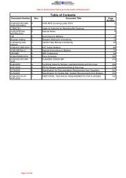
Click on the Document Title to go to that section of the document<br />
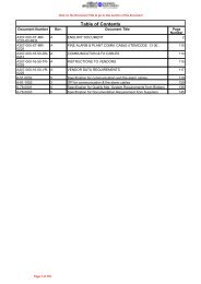
Table of Contents<br />
Document Number Rev. Document Title Page<br />
Number<br />
A307-0IG-JU-MR- A ENQUIRY DOCUMENT 4<br />
6519-61-RFQ<br />
A307-0IG-JU-MR- A SILENCERS 105<br />
6519<br />
A166-IG-1155 5 PID44 111<br />
A166-IG-1114 5 PID3 112<br />
A307-0IG-02-41-DS- 0 SILENCER D/S 113<br />
1903<br />
A307-6-44-0006- A VMS For Silencers 114<br />
6519<br />
A307-0IG-16-46-SK- A JOB SKETCHES 116<br />
1000<br />
A307-0IG-02-41-DS- 0 SILENCER D/S 117<br />
1901<br />
A166-IG-1121 5 PID10 118<br />
A307-0IV-16-46-DS- A MECHANICAL DATASHEETS 119<br />
4314<br />
A166-IV-1159-PID 0 P&ID 122<br />
7-12-0030 4 Name plate for small equipment. 123<br />
A307-0IG-02-41-DS- 0 SILENCER D/S 124<br />
1902<br />
7-12-0026 5 Earthing lug. 125<br />
7-12-0025 5 Fire proofing & insulation supports. 126<br />
A307-6-44-0005-<br />
6519<br />
A PMS for silencers 128<br />
IV-LZ-211 0 MISCELLANEOUS 142<br />
7-12-0015 5 Standard bolt hole orientation. 144<br />
7-12-0013 6 Nozzle reinforcement and projection. 145<br />
7-12-0008 5 Bracket support for vertical vessel. 147<br />
A307-0IG-16-46- A VDR FOR VDR COMPILATION 148<br />
VDR-6519<br />
7-12-0001 5 Vessel tolerances. 151<br />
6-81-0011 3 ITP for pressure vessels / columns carbon steel. 153<br />
A307-16-46-TR-6519 A INSTRUCTIONS TO VENDOR/ TECHNICAL REQUIREMENTS 160<br />
IV-LZ-214 0 DATA SHEET 162<br />
A307-0IV-16-46-DS- A MECHANICAL DATASHEETS 164<br />
4313<br />
A166-IV-1139-PID 0 P&ID 167<br />
A307-16-46-LL-6519 A LIST OF ATTACHMENTS 168<br />
6-78-0003 0 Specification for Documentation Requirement from Suppliers 170<br />
A307-16-46-SP-6519 A MR JOB SPECIFICATION 182<br />
A307-16-46-UR-6519 A UNIT RATES FOR ADDITION AND DELETIONS 187<br />
6-78-0001 0 Specification for Quality Mgt. System Requirements from Bidders 190<br />
A307-0IV-16-46-DS- A MECHANICAL DATASHEETS 199<br />
4312<br />
IV-LZ-213 0 DATA SHEET 202<br />
A166-IV-1161-PID 0 P&ID 204<br />
A307-0IG-16-46-ST- A JOB STANDARDS 205<br />
0038<br />
A307-0IG-16-46-DS- A MECHANICAL DATASHEETS 210<br />
4105<br />
6-12-0030 7 Standard specification for pressure vessels for package items. 213<br />
IV-LZ-212 0 MISCELLANEOUS 232<br />
Page 2 of 291
Table of Contents<br />
Document Number Rev. Document Title Page<br />
A307-0IV-16-46-DS-<br />
4311<br />
A307-0IG-16-46-DS-<br />
4106<br />
A307 00 06 42 PLS<br />
01<br />
A307-0IG-16-46-DS-<br />
4116<br />
Number<br />
A MECHANICAL DATASHEETS 234<br />
A MECHANICAL DATASHEETS 237<br />
0 REFERENCE VENDOR DRAWING 240<br />
A MECHANICAL DATASHEETS 289<br />
Page 3 of 291
EI Bhawan Annexe, Bhikaiji Cama Place, RK Puram, New Delhi – 110 066, INDIA<br />
Phone No : 0091-11-26762121 ; Fax No : 0091-11-26191714, 26167664<br />
REQUEST FOR QUOTATION (RFQ)<br />
RFQ No. : SM/A307-IG-JU-MR-6519/61 Date: 08 – NOV - 2013<br />
Client :<br />
BHARAT PETROLEUM CORPN. LIMITED<br />
Project: INTEGRATED REFINERY EXPANSION PROJECT<br />
AT KOCHI REFINERY<br />
MR No.: A307-IG-JU-MR-6519 REV.A<br />
Item:<br />
SILENCERS<br />
Due Date & Time: 29 - NOV - 2013 & Up to 1200 Hrs. (IST)<br />
UNPRICED BID OPENING:<br />
PRICED BID OPENING:<br />
At 1400 Hrs. (IST) on 29 - NOV - 2013 (at EIB - 5th Floor,<br />
Engineers India Limited, Bhikaiji Cama Place, R.K. Puram,<br />
New Delhi – 110066, India) (In case the bid due date happens to<br />
fall on Holiday, the next working day shall be deemed to be due<br />
date)<br />
TIME & VENUE SHALL BE INTIMATED LATER.<br />
Gentlemen,<br />
Bids are requested on behalf of our Client M/s Bharat Petroleum Corporation Limited on e-procurement<br />
system for the subject item in total compliance to technical specifications, scope, terms & conditions of enquiry<br />
documents / attachments.<br />
1. Bidder should submit their bids strictly as per the requirements outlined hereunder and as specified in<br />
the material requisition.<br />
2. Bids are required to be submitted through <strong>EIL</strong>’s Authorized Service Provider’s (ASP) Electronic System /<br />
Portal at www.tenderwizard.com/eil only, on or before the bid submission date and time. Bidders are<br />
required to register themselves at www.tenderwizard.com/eil . No registration fee would be charged from<br />
the bidders.<br />
Bidders to refer attached Instructions to Bidders for E-<strong>Tender</strong>ing.<br />
3. Bidders in their own interest are requested to register on e- tendering <strong>portal</strong> and upload/submit their bid<br />
well in time. Bidders should avoid the last hour rush to the website for registration of user id & password,<br />
enabling of user id and mapping of digital signature serial number etc. since this exercise require<br />
activities from <strong>EIL</strong> & M/s Anatares System (Service Provider) and needs time. In the event of failure in<br />
bidder’s connectivity with <strong>EIL</strong>/Service Provider during the last few hours, bidder is likely to miss the<br />
deadline for bid submission.<br />
Due date extension request due to above reason may not be entertained.<br />
4. Bidders are required to upload the complete bid comprising of Part-I:- Unpriced Bid along with all<br />
supporting documents & Part-II :- Priced Bid on the e-tendering website (www.tenderwizard.com/eil)<br />
only.- Refer General Instruction provided in SIB .<br />
5. Technical specification should be strictly as per the Material Requisition attached. It may be noted that<br />
the Bid shal be evaluated as received and technical queries may not be issued.<br />
6. Commercial requirements are specified in the Special Instructions to Bidders, General Purchase<br />
Conditions, Agreed Terms & Conditions (ATC) questionnaire and all other RFQ documents. The prefilled<br />
Agreed Terms & Conditions Questionnaire should be returned duly signed and stamped along with<br />
copy of your un-priced bid.<br />
7. The order, if placed, will be issued by our above-mentioned client.<br />
Page 1 of 5<br />
Page 4 of 291
8. If not bidding, please inform vide E-mail with attached regret letter within the due date & time, with<br />
reasons(s) of not participating in the RFQ. In case there is no response, names of such bidder may not<br />
be considered for issuance of future enquiries.<br />
9. Direct bids only, without the intermediary of an Indian Agent will be considered from Foreign Bidder.<br />
10. Delivery Period:- Within 06 Months on FOT Despatch Point Basis from the date of Fax of<br />
Acceptance. Date of LR/GR shall be considered the date of delivery.<br />
11. Payment Terms shall be as per following:- The payment to Indian bidders shall be made in accordance<br />
with S. No. 1.2 & 1.7 Under Section A of Special Instruction to Bidders (SIB).<br />
12. The offer should be valid for 3 (Three) months from final bid due date.<br />
13. Only E-Bids to be uploaded in <strong>EIL</strong>’s authorized service provider’s <strong>portal</strong><br />
www.tenderwizard.com/eil shall be acceptable. Physical bids and Bids/ Offer through Email or fax/<br />
Telex/Telegraphic or Bids received in open condition or Bids in any other mode shall not be accepted.<br />
13. The bidder shall bear all costs associated with the preparation and submission of its bid, and the<br />
Purchaser/Consultant shall in no case be responsible or liable for these costs regardless of the<br />
conduct or outcome of the bidding process.<br />
14 . Canvassing in any form by the Bidder or by any other agency on their behalf may lead to<br />
disqualification of their bid.<br />
15 . The E-bids received online shall be opened at <strong>EIL</strong> office on due date and time as specified above.<br />
Bidder can view online the name of the other bidders who have submitted their e-bids after opening is<br />
performed by <strong>EIL</strong>.<br />
16 . All technically and commercially acceptable bidders will be advised of venue, date and time of priced<br />
bid opening. Bids shall be opened online, hence bidders may review opening status at their places.<br />
Interested bidder may sent their representatives (duly authorised by a competent person and having<br />
the Letter of Authority as per proforma enclosed), of such technically and commercially acceptable<br />
bidders. Time and Date of opening of Price Bids shall be notified to the qualified and acceptable<br />
bidders at a later date.<br />
17 . As Purchaser intends to contract directly with suppliers of the goods for which bids are invited, the<br />
bids should be prepared by the suppliers and submitted directly. Purchaser reserves the right to reject<br />
offers made by intermediaries.<br />
18 . Addendum / corrigendum to the RFQ documents if issued must be signed and submitted along with<br />
the bid.<br />
19 . Bidders to note that price changes against Technical / commercial clarifications, in line with terms &<br />
conditions of enquiry documents are not allowed. In case any bidder gives revised prices / price<br />
implications against such clarifications, their bid shall be liable for rejection.<br />
20 <strong>EIL</strong> reserves the right to use in-house information for assessment of bidder’s capability for<br />
consideration of bid.<br />
21 In case any bidder is found to be involved in cartel formation, his bid will not be considered for<br />
evaluation / placement of order. Such bidder will also be debarred from bidding in future.<br />
22 The bidder who is providing the technology from the company which is recently acquired / taken over<br />
by them or purchasing the technology by other companies, shall be provide proper documentary<br />
evidence. In the absence of the same their offer shall be liable for rejection.<br />
23 Bidders are requested to quote as per their capability as registered in <strong>EIL</strong>, as on the date of issue of<br />
RFQ.<br />
24 Owner reserves its right to allow Public Sector Enterprises (Central/State), Micro & Small Enterprises<br />
(MSEs) and MSEs owned by Scheduled Caste (SC)/ Scheduled tribe (ST) entrepreneurs, purchase<br />
preference as admissible/applicable from time to time under the existing Govt. policy. Bidder to<br />
submit documentary evidence for the same duly certified by Statutory Auditor of the bidder or a<br />
practicing Chartered Accountant (not being an employee or a Director or not having any interest in the<br />
Bidder’s company / firm) where audited accounts are not mandatory as per law.). In this regard, item<br />
wise quantity may be splitted and the quoted price shall remain valid.<br />
Page 2 of 5<br />
Page 5 of 291
25 The Net Worth of the bidder should be positive as per the immediate preceding year's audited<br />
financial results. However, Central Public Sector Enterprises (CPSEs) are exempted from this<br />
requirement. If the bidder is not meeting the above criteria their bid shall not be evaluated further.<br />
Bidders are therefore requested to furnish the Audited Financial Statement for the immediate<br />
preceding year including Profit & Loss Account.<br />
26 Purchaser reserve the right to make any changes in the terms and conditions of purchase and to<br />
reject any or all the bids.<br />
27 Category of MR:<br />
i) Please note that this is a Category-I MR whereby no technical offers are invited and no<br />
correspondence shall be entered into or entertained after bid submission.<br />
ii)<br />
iii)<br />
No technical details of any nature shall be included in the offer and if the offer contains<br />
any technical deviations or clarifications or stipulates any technical specifications, the<br />
offer shall be liable for rejection.<br />
The submission of prices by vendor shall be construed to mean that the vendor has confirmed<br />
compliance with all technical specifications of the correspondence item.<br />
Contact Persons for this RFQ are:<br />
Mr Subhendu Mondal, AGM(C&P), Phone No. +91-(0)11-2676-3883 & email: subhendu.mondal@eil.co.in<br />
Mr Anindya Sinha, Manager (C&P), Phone No, +91-(0)11-2676-3886 & email: anindya.sinha@eil.co.in<br />
Ms. Vibha Bharti, Engineer (C&P), Phone No. +91-(0)11-2676-3874 & email: vibha.bharti@eil.co.in<br />
* Please specify RFQ. No. SM/A307-IG-JU-MR-6519/61 in all Correspondence.<br />
THIS IS NOT AN ORDER<br />
Very truly yours,<br />
For & on behalf of<br />
Bharat Petroleum Corporation Limited<br />
Enclosure: As per List Attached<br />
(SUBHENDU MONDAL)<br />
ASST. GEN. MANAGER(C&P)<br />
ENGINEERS INDIA LIMITED<br />
Page 3 of 5<br />
Page 6 of 291
LIST OF ENCLOSURES<br />
DOCUMENT<br />
A) Request For Quotation (RFQ)<br />
B) Proforma of Letter of Authority for Attending Un-priced / Priced Bid Opening<br />
C) Price Schedule Format<br />
D) Commercial document:<br />
i) Agreed Terms & Conditions (For Indian Bidders)<br />
ii) Special Instruction to Bidders (SIB)<br />
iii) General Purchase Conditions (Indian)<br />
iv) Proforma of Bank Guarantee (Performance) / Advance Bank Guarantee<br />
v) Instruction to Bidders for e-tendering.<br />
vi) E-<strong>Tender</strong>ing Help Manual for Bidders<br />
vii) Browser Settings<br />
E) Technical document MR No. A307-IG-JU-MR-6519 Rev. A<br />
Page 4 of 5<br />
Page 7 of 291
Proforma of Letter of Authority<br />
for Attending Unpriced / Priced Bid Opening<br />
No.<br />
Date:<br />
The Asst.General Manager (C&P)<br />
Engineers India Limited<br />
Engineers India Bhawan EIB-5th Floor<br />
1-Bhikaiji Cama Place<br />
New Delhi – 110 066<br />
India<br />
Attn. : Mr. S.MONDAL<br />
Dear Sir,<br />
We ………………………………………..hereby authorise following representative(s) to attend the<br />
Unpriced / Priced Bid Opening against your RFQ No……………..……… .……………..………… for<br />
……………..….……………………… (Item Name)<br />
1. Name & Designation …………………………. Signature ……………………….<br />
2. Name & Designation …………………………. Signature ……………………….<br />
We confirm that we shall be bound by all and whatsoever our representative(s) shall commit.<br />
Yours faithfully,<br />
Signature _________________________<br />
Name & Designation ________________<br />
For & on behalf of __________________<br />
Note:<br />
This Letter of Authority should be on the letterhead of the bidder and should be signed by a<br />
person competent and having the Power of Attorney to bind the bidder.<br />
Page 5 of 5<br />
Page 8 of 291
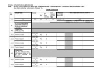
PREAMBLE TO PRICE SCHEDULE (INDIAN)<br />
RFQ NO. SM/A307-IG-JU-MR-6519/61<br />
ITEM : SILENCERS<br />
1<br />
2<br />
3<br />
4<br />
5<br />
6<br />
7<br />
8<br />
9<br />
10<br />
11<br />
12<br />
Bidder must quote Transportation Charges inclusive of Service Tax plus ed. Cess thereupon in the space provided in the price schedule as per MR.<br />
Bidder shall furnish built-in CIF value if any, against each quoted item, giving details of description of goods, qty. rate of Custom Duty etc. in attached FORM- 2..<br />
Bidder must quote the price in enclosed Price Schedule formats only. The formats shall not be changed and/or retyped.<br />
In case of any discrepancy between Unit Price and Total Price, Unit Price shall prevail.<br />
NAME OF BIDDER: M/S __________________________<br />
Scope of supply including testing, inspection, documentation etc., shall be strictly as per Material Requisition and other documents which are part of RFQ.<br />
All the Columns of quoted items in the Price Schedule must be filled with required information, as applicable.<br />
Quoted prices are firm and fixed till complete execution of the entire order and no variation on any account is allowed.<br />
Bidders shall quote Unit Rates for Addition/ Deletion purpose, as per Format provided with Material Requisition.<br />
Bidder to note that inspection shall be carried out by <strong>EIL</strong> and the charges for the same shall be borne by Owner. However, in case of certain Import Contents as required by bidder for subject item<br />
the same shall be procured under TPIA (Lloyds/BV/DNV/TUV/C<strong>EIL</strong>) inspection in the country of origin and the quoted prices shall be inclusive of the same.<br />
Bidder must submit signed and stamped Un-Priced copy of Price Schedule indicating "Quoted" or "Not Quoted" against each item with their Unpriced offer.<br />
Evaluation shall be done on itemwise basis (Supply + Transportation).<br />
Bidder to confirm that he has noted the contents of the Preamble to the Price Schedule, Price Schedule, RFQ, Material Requisition etc and quoted his prices accordingly without any deviation.<br />
NOTES:<br />
1. Bidders must submit this document duly signed and stamped with both unpriced & priced offer.<br />
2. Price Schedule contains total 3 pages .<br />
Page 9 of 291
PRICE SCHEDULE (INDIAN BIDDER)<br />
RFQ NO. SM/A307-IG-JU-MR-6519/61<br />
ITEM : SILENCERS<br />
NAME OF BIDDER: M/S __________________________<br />
ITEM SL.<br />
NO. AS<br />
PER MR.<br />
DESCRIPTION/ TAG NO.<br />
QTY<br />
(IN NOS.)<br />
Total Price on FOT Despatch<br />
Point Basis incl. of P & F (in<br />
Rs.)<br />
Total Transportation Charges upto<br />
Project Site Inclusive of Service<br />
Tax + Ed. Cess. (in Rs.)<br />
01.00<br />
Supply of SILENCERS for following Tags/ Items as per complete<br />
scope mentioned in Material Requisition No. A307-IG-JU-MR-6519<br />
01.01 TAG NO. : IG-LZ-105 (STEAM GENERATOR 1 SILENCER) 1<br />
01.02 TAG NO. : IG-LZ-106 (STEAM GENERATOR 2 SILENCER) 1<br />
01.03 TAG NO. : IG-LZ-116 (LP STEAM DESUPERHEATER 1 SILENCER) 1<br />
01.04 TAG NO. : IV-LZ-211 (LP STEAM VENT SILENCER) 1<br />
01.05 TAG NO. : IV-LZ-212 (MP STEAM VENT SILENCER (IBR)) 1<br />
01.06 TAG NO. : IV-LZ-213 (LP STEAM VENT SILENCER) 1<br />
01.07 TAG NO. : IV-LZ-214 (LP STEAM VENT SILENCER) 1<br />
Unit rates of items for addition/deletion purpose, as per enclosed<br />
06.00 1<br />
Doc. A307-16-46-UR-6519 of MR.<br />
BIDDER TO FURNISH THE UNIT RATES FOR ADDITION /<br />
DELETION IN THE FORMAT PROVIDED WITH MR ONLY.<br />
Page 10 of 291<br />
Page 2 of 3
FORM-2<br />
ENCLOSURE TO PRICE SCHEDULE FOR SUPPLY<br />
RFQ NO. SM/A307-IG-JU-MR-6519/61<br />
ITEM : SILENCERS<br />
NAME OF BIDDER: M/S __________________________<br />
FORMAT - "CIF/CD"<br />
DETAILS OF BUILT-IN-CIF VALUE OF IMPORT CONTENT CONSIDERED AND INCLUDED IN QUOTED FOT DESPATCH POINT PRICES UNDER PRICE SCHEDULE<br />
DESCRIPTION<br />
For Item Sl Description<br />
. No. as per of Imported<br />
MR<br />
Items<br />
Qty.<br />
(Unit____)<br />
*(1)<br />
CIF value of Import<br />
Content included in<br />
quoted supply<br />
prices for column<br />
(2) Qty.<br />
(In Rs)<br />
CUSTOM<br />
TARIFF<br />
NO.<br />
RATE OF IMPORT DUTY INCLUDED IN QUOTED SUPPLY PRICES<br />
BASIC<br />
CUSTOMS<br />
DUTY (%)<br />
CVD + EDU.<br />
CESS ON CVD<br />
(%)<br />
EDU. CESS<br />
ON<br />
CUSTOM<br />
DUTY (%)<br />
SAD (%) TOTAL CUSTOM<br />
DUTY (%)<br />
1 2 3 4 5 6 7 8 9<br />
For Item<br />
SL. No<br />
01.00<br />
TOTAL CIF VALUE<br />
Page 11 of 291
A307_ATC (I) Page 1 of 8<br />
BHARAT PETROLEUM CORPORATION LTD<br />
IREP-Kochi Refinery<br />
(Job No. A307)<br />
AGREED TERMS & CONDITIONS (ATC)<br />
(FOR INDIAN BIDDERS)<br />
Supplier Name: M/s ______________________________________________________________<br />
RFQ No.:<br />
__________________________________________________________________<br />
Supplier’s Offer Ref No. & Date: ______________________________________________________<br />
Tel. No. ___________________Mob. No. ______________________ Fax No. ________________<br />
Contact Person: ___________________________ E-mail _________________________________<br />
1. ALL CORRESPONDENCE MUST BE IN ENGLISH LANGUAGE ONLY.<br />
2. DULY SIGNED & STAMPED COPIES OF THIS “QUESTIONNAIRE”, WITH ALL THE<br />
CLAUSES DULY CONFIRMED/ PRECISELY REPLIED TO BY THE SUPPLIER, SHALL BE<br />
ENCLOSED.<br />
3. ALL COMMERCIAL TERMS ARE GIVEN/CONFIRMED IN THE QUESTIONNAIRE ITSELF<br />
AND NOT ELSEWHERE IN THE QUOTATION. IN CASE OF CONTRADICTION, THE SAME<br />
GIVEN HEREIN SHALL PREVAIL.<br />
4. FAILURE ON PART OF THE SUPPLIER IN SUBMITTING THIS DULY FILLED-IN<br />
“QUESTIONNAIRE” WITH UN-PRICED BID AND/ OR SUBMITTING INCOMPLETE<br />
REPLIES MAY LEAD TO REJECTION OF SUPPLIER’S BID.<br />
5. YOUR OFFER SHALL BE IN TOTAL COMPLIANCE WITH RFQ DOCUMENTS<br />
CONTAINING COMMERCIAL AND TECHNICAL SPECIFICATIONS INCLUDING GENERAL/<br />
TECHNICAL NOTES AND SCOPE OF SUPPLY/SERVICES/ SITE WORK, AS APPLICABLE<br />
INCLUDING DOCUMENTATION AS PER MATERIAL REQUISITION (MR) AND<br />
SUBSEQUENT TECHNICAL/ COMMERCIAL AMENDMENT AND TECHNICAL/<br />
COMMERCIAL CORRIGENDUM, IF ANY.<br />
SL.<br />
NO.<br />
1.<br />
i)<br />
ii)<br />
iii)<br />
a)<br />
b)<br />
iv)<br />
Price Basis:<br />
DESCRIPTION<br />
Quoted supply prices are on FOT - Despatch Point basis<br />
inclusive of Packing & Forwarding.<br />
Specify Despatch Point<br />
Freight Charges:<br />
Confirm firm transportation charges inclusive of Service Tax<br />
and Ed Cess, upto project site, has been quoted separately<br />
by you in Price Schedule.<br />
No Variation on any account (including Statutory Variation) on<br />
Service Tax on Transportation Charges shall be paid by the<br />
owner.<br />
Insurance:<br />
a) For Supply Only<br />
Transit/Marine Insurance of Equipment/ Item has been taken<br />
care by the Owner & charges of the same have not been<br />
included in the quoted prices.<br />
SUPPLIER’S CONFIRMATION<br />
Confirmed<br />
-----------------------<br />
a) Confirmed , Quoted in Price<br />
Schedule<br />
b) Confirmed<br />
Confirmed.<br />
SUPPLIER’S SIGNATURE WITH STAMP/SEAL<br />
Page 12 of 291
A307_ATC (I) Page 2 of 8<br />
SL.<br />
NO.<br />
DESCRIPTION<br />
SUPPLIER’S CONFIRMATION<br />
2.<br />
a.<br />
b.<br />
c.<br />
d.<br />
e.<br />
f.<br />
g.<br />
h.<br />
3.<br />
a.<br />
b.<br />
c.<br />
d.<br />
e.<br />
b) For Supply + Site Work<br />
Comprehensive Insurance (Transit/Marine-cum-storage-cumerection<br />
till handing over of equipment) has been taken care<br />
by the Seller & charges of the same have been included in<br />
the quoted prices.<br />
Excise Duty applicable extra on Finished Goods:<br />
Specify Excise Tariff Sub-Heading No.<br />
Present Rate of Excise Duty & Edu. Cess payable extra on<br />
finished goods (including Spares)<br />
Any variations in Excise Duty & Edu. Cess at the time of<br />
supplies for any reasons including variation due to Turnover<br />
shall be borne by the Seller. Only Statutory Variations within<br />
the Contractual Delivery / completion period shall be borne by<br />
Purchaser.<br />
If Excise Duty & Edu. Cess is not applicable at present due to<br />
any reason, the same shall be borne by Seller if it becomes<br />
applicable later.<br />
Confirm Excise Duty & Edu. Cess will not be applicable on<br />
transportation charges.<br />
If Excise Duty & Edu. Cess is not applicable on transportation<br />
charges presently, and if it becomes applicable at the time of<br />
delivery due to any reasons other than statutory, the same will<br />
be borne by the Supplier. Confirm acceptance.<br />
Non Cenvatable Excise Duty, if any is included in quoted<br />
prices & no variation on any account (including statutory<br />
variation) shall be paid by Owner.<br />
Only Statutory Variations, if any, in the present rate of Excise<br />
Duty, upto the Contractual Delivery Date / Completion Period<br />
shall be to Owner’s account subject to documentary evidence<br />
to be furnished by Seller.<br />
Sales Tax applicable extra on finished goods:<br />
Central Sales Tax against Concessional Form “C” payable<br />
extra on finished goods (including spares) is applicable & the<br />
present rate (in %age) is indicated<br />
Kerala VAT payable extra on finished goods (including<br />
spares) without concessional form is applicable & the present<br />
rate (in %age) is indicated<br />
If CST / Kerala VAT is not applicable at present due to any<br />
reason, the same shall be borne by Supplier if it becomes<br />
applicable later.<br />
Confirm CST/ Kerala VAT will not be applicable on<br />
transportation charges.<br />
If CST / Kerala VAT is not applicable on transportation<br />
charges presently, and if it becomes applicable at the time of<br />
delivery due to any reasons other than statutory, the same will<br />
be borne by the Supplier. Confirm acceptance.<br />
Confirmed<br />
_________________<br />
………..%<br />
Confirmed<br />
Confirmed<br />
Confirmed<br />
Confirmed<br />
Confirmed<br />
Confirmed<br />
(Applicable / Not Applicable)<br />
(Please tick whichever is applicable)<br />
…………%<br />
(Applicable / Not Applicable)<br />
(Please tick whichever is applicable)<br />
………….%<br />
Confirmed<br />
Confirmed<br />
Confirmed<br />
SUPPLIER’S SIGNATURE WITH STAMP/SEAL<br />
Page 13 of 291
A307_ATC (I) Page 3 of 8<br />
SL.<br />
NO.<br />
DESCRIPTION<br />
SUPPLIER’S CONFIRMATION<br />
h. Only Statutory Variations, if any, in the present rate of CST /<br />
Kerala VAT, upto the Contractual Delivery Date / Completion<br />
Period shall be to Owner’s account subject to documentary<br />
evidence to be furnished by Seller.<br />
4. Octroi / Entry Tax:<br />
Octroi / Entry Tax, if applicable on finished goods (including<br />
spares) shall be borne and paid directly by Owner. Confirm<br />
that Octroi / Entry Tax has not been included in the quoted<br />
prices.<br />
5. Any new or additional taxes/ duties and any increase in the<br />
existing Cenvatable taxes/duties imposed after contractual<br />
completion period shall be to Supplier’s account whereas any<br />
corresponding decrease in the existing Cenvatable taxes/<br />
duties shall be passed on to the Owner.<br />
6.<br />
a.<br />
Spares Parts:<br />
Confirm item wise unit price (FOT Despatch Point) of<br />
following spare parts as required in Material Requisition (MR)<br />
have been included indicating itemised quantity.<br />
i) Mandatory Spares are quoted as per MR.<br />
ii) Commissioning spares as specified in MR are included in<br />
the quoted Price.<br />
iii) Special Tools & Tackles as specified in the MR are<br />
included in the quoted prices.<br />
iv) Confirm spares wherever required have been included in<br />
the quoted price and list of spares is also furnished.<br />
v) Recommended Spares for Two Years Operation &<br />
Maintenance, as specified in MR have been quoted<br />
separately with Price validity of One (1) year from Contractual<br />
Delivery Date for Main Items/Equipment & List of such spares<br />
has been furnished in the Unpriced Bid.<br />
Confirmed<br />
Confirmed<br />
Confirmed<br />
Confirmed<br />
Confirmed (if Applicable as per MR)<br />
Confirmed (if Applicable as per MR)<br />
Confirmed (if Applicable as per MR)<br />
Confirmed (if Applicable as per MR)<br />
Confirmed (if Applicable as per MR)<br />
7.<br />
a.<br />
b.<br />
c.<br />
d.<br />
Site Work:<br />
For Site Work, if in the scope of the Bidder as per MR, please<br />
confirm the following:<br />
Confirm that quoted site work prices are exclusive of Service<br />
Tax & Edu. Cess but inclusive of VAT on Works Contract and<br />
all other applicable taxes & duties.<br />
Percentage of Service Tax & Edu. Cess as applicable extra<br />
on Site Work.<br />
Supplier shall submit the Assessment/ Liability<br />
Certificate from Sales Tax authorities indicating the VAT<br />
on Works Contract payable for enabling Owner to<br />
deduct the same from Supplier Invoices & make<br />
payment to the tax authorities. TDS Certificate towards<br />
VAT on Works Contract shall be provided by Owner.<br />
Statutory variation on VAT on Works Contract shall not<br />
be payable by Owner.<br />
Statutory Variation on Service Tax & Edu. Cess on Site work<br />
shall be paid by the Owner against documentary evidence<br />
within Contractual completion period.<br />
Confirmed<br />
-------------------%<br />
Confirmed<br />
Confirmed<br />
SUPPLIER’S SIGNATURE WITH STAMP/SEAL<br />
Page 14 of 291
A307_ATC (I) Page 4 of 8<br />
SL.<br />
NO.<br />
DESCRIPTION<br />
SUPPLIER’S CONFIRMATION<br />
e. Confirm that Entry Tax / Octroi applicable on Construction<br />
Machinery/Equipment brought by the supplier to site to<br />
execute / complete the site work shall be borne by the<br />
Supplier and same is included in the quoted prices. No<br />
variation (including statutory) on such entry tax shall be paid<br />
by the Owner.<br />
Confirmed<br />
8.<br />
a.<br />
b.<br />
c.<br />
d.<br />
e.<br />
Supervision / Training Charges:<br />
Charges for Supervision / Training, if in the scope of the<br />
Bidder as per MR have been indicated by bidder separately in<br />
the Price Schedule.<br />
Percentage of Service Tax & Edu. Cess as applicable extra<br />
on Supervision / Training<br />
Per-diem rate for supervision has been quoted in accordance<br />
with the Terms & Conditions for Supervision enclosed with the<br />
RFQ Documents.<br />
Where erection/ testing/ commissioning supervision,<br />
commissioning assistance is required as per RFQ Documents<br />
/ Material requisition, penalty for non mobilization/delay in<br />
mobilization as per order shall be applicable. The penalty<br />
shall generally be 1.5 times the per diem rate for each day of<br />
delay of reporting to site and shall be in addition to price<br />
reduction for delayed delivery.<br />
Bidders shall also provide additional BG of an amount equal<br />
to the per diem charges for the number of days considered for<br />
evaluation, over and above 10% PBG to cover compensation<br />
for delay in mobilizing the erection/ commissioning personnel.<br />
This BG will be released to the bidder upon the erection/<br />
commissioning personnel reporting at site. This BG shall be<br />
furnished along with payment milestone for submission of<br />
final documentation as per MR and shall be initially valid up to<br />
six months which shall be extended based on the request by<br />
Owner.<br />
Confirmed, Quoted in Price<br />
Schedule<br />
----------------%<br />
Confirmed<br />
Noted & Confirmed<br />
Noted & Confirmed<br />
9. Confirm documentation charges as per MR are included in<br />
quoted prices.<br />
Confirmed<br />
10. Price Reduction for delay in delivery/ completion:<br />
a) Confirm acceptance of price reduction schedule for delay in<br />
deliveries / completion as specified in GPC & Special<br />
Instructions to Bidders (SIB) enclosed in RFQ Document.<br />
Liquidated damages or penalty are not acceptable.<br />
b) In case of delay, vendor will reduce the invoice amount by<br />
applicable reduction.<br />
11. Delivery / Completion Period:<br />
Please confirm delivery / completion period as specified in the<br />
RFQ Covering Letter.<br />
12. Payment Terms:<br />
Confirm acceptance of “Terms and Mode of Payment” as per<br />
respective clause(s) given in SIB and RFQ covering letter.<br />
Confirmed<br />
Confirmed<br />
Confirmed<br />
Confirmed<br />
SUPPLIER’S SIGNATURE WITH STAMP/SEAL<br />
Page 15 of 291
A307_ATC (I) Page 5 of 8<br />
SL.<br />
NO.<br />
13.1<br />
a.<br />
DESCRIPTION<br />
PART ORDER:<br />
Confirm acceptance of Part Order clause as per GPC<br />
(Indigenous). And bidder also confirm acceptance to part<br />
quantity orders of any items (having quantities 5 Nos. & more)<br />
to facilitate purchase preference to MSME bidders as per<br />
Govt. guide lines.<br />
13.2 MSME BIDDERS:<br />
a<br />
Confirm whether the bidder is a MSME bidder or not.<br />
b In case bidder is a MSME bidder, they must submit<br />
documentary evidence for the same duly certified by<br />
Statutory Auditor of the bidder or a practicing Charted<br />
Account (not being an employee or a Director or not<br />
having any interest in the Bidder’s company/ firm) where<br />
audited accounts are not mandatory as per law.<br />
c In case bidder does not submit duly authenticated<br />
documentary evidence as required above, bidder shall<br />
not be considered eligible for availing MSME benefits.<br />
d Any charges quoted extra as lumpsum (like IBR,<br />
Testing, freight, etc.) shall be applicable prorata on<br />
value basis in the event of part order / part quantities/<br />
split order.<br />
14. Repeat Order:<br />
Confirm Acceptance of Repeat Order clause as per RFQ<br />
Covering Letter / SIB / GPC.<br />
15. Performance Bank Guarantee:<br />
a) In the event of award of order, submission of Performance<br />
Bank Guarantee for 10% of total order value along with<br />
Final supply payment valid till full guarantee period plus 3<br />
(Three) months.<br />
b) The Performance Bank Guarantee shall be strictly as per<br />
enclosed proforma and shall be from any Indian<br />
Scheduled Bank or branch of an International Bank<br />
situated in India and registered with Reserve Bank of<br />
India as scheduled foreign Bank.<br />
16. Guarantee / Warranty:<br />
Confirm acceptance to Guarantee / Warranty clause as<br />
mentioned in the GPC/SIB.<br />
17. Firmness of prices:<br />
Confirm quoted prices shall remain firm and fixed till complete<br />
execution of order. Price Variation shall not be considered on<br />
any account.<br />
SUPPLIER’S CONFIRMATION<br />
Confirmed (If Applicable as per MR)<br />
YES/ NO<br />
(Please tick whichever is applicable)<br />
_________________<br />
Confirmed<br />
Confirmed<br />
Confirmed<br />
Confirmed<br />
Confirmed<br />
Confirmed<br />
Confirmed<br />
18.<br />
a.<br />
b.<br />
Testing and Inspection charges:<br />
Goods supplied are subject to stage wise and final inspection<br />
as specified in MR by <strong>EIL</strong> and no extra charges shall be<br />
payable by Owner towards the same. Travel, Living and<br />
Personnel expenses of <strong>EIL</strong>’s Representative shall be borne<br />
by Owner.<br />
Quoted prices are:<br />
i) Inclusive of all testing and inspection charges (if applicable)<br />
as per MR.<br />
ii) Inclusive of all IBR/IGC/NACE charges (if applicable) as<br />
required in the Material Requisition.<br />
Confirmed<br />
Confirmed<br />
SUPPLIER’S SIGNATURE WITH STAMP/SEAL<br />
Page 16 of 291
A307_ATC (I) Page 6 of 8<br />
SL.<br />
NO.<br />
c.<br />
19.<br />
a.<br />
b.<br />
c.<br />
d.<br />
e.<br />
f.<br />
g.<br />
h.<br />
i.<br />
j.<br />
k.<br />
DESCRIPTION<br />
iii) Inclusive of all statutory certification charges PESO/CCOE<br />
etc. (if applicable) as required in the Material Requisition<br />
Is your shop approved by IBR/CCE authority, if yes, indicate<br />
validity.<br />
i. IBR<br />
ii. CCE<br />
It is the responsibility of supplier to get the entire imported<br />
materials and the built in imported contents inspected by TPIA<br />
(i.e. Lloyds/BV/DNV/TUV/C<strong>EIL</strong>) in the country of origin and<br />
the quoted prices are inclusive of charges towards the same.<br />
Import Content:<br />
If your offer is based on certain imported raw materials<br />
required for equipments/ materials offered, please specify the<br />
following :<br />
Confirm that quoted prices are based on Merit rate of<br />
Customs duty, CVD, Educational Cess and SAD as<br />
applicable.<br />
Indicate rate of Import Duties considered and included in the<br />
quoted prices.<br />
Indicate brief description/ specification with itemised CIF<br />
value and country of origin of imported material.<br />
Indicate classification with tariff no. under which Vendor<br />
intends to import.<br />
Confirm prices shall be firm on account of variation in foreign<br />
exchange rate.<br />
Owner shall not provide any import licence.<br />
Quoted prices are after considering the benefit of CENVAT on<br />
CVD including Edu. Cess. In case material is shipped directly<br />
to Port/Project Site, quoted prices are excluding CENVAT<br />
benefit.<br />
In case material is directly dispatched from port, CVD amount<br />
shall be reimbursed subject to submission of bill of entry<br />
documents along with CVD invoice.<br />
Any upward variation due to change in Customs Duty<br />
classifications shall be absorbed by the vendor. However, any<br />
reduction in customs duty due to change in classification shall<br />
be passed on to Owner.<br />
Statutory variations, if any, in the rate of Import Duties upto<br />
2/3 rd contractual delivery period shall be to Owner’s account.<br />
Any increase in price due to increase in the rate of Import<br />
Duties, due to any reasons, whatsoever, beyond the 2/3 rd<br />
contractual delivery period, shall be to vendor's account.<br />
However, any decrease in Import Duties rate at the time of<br />
actual clearance of imported materials shall be passed on to<br />
Owner.<br />
SUPPLIER’S CONFIRMATION<br />
Confirmed<br />
Confirmed<br />
IBR Approved<br />
Confirmed<br />
(Applicable / Not Applicable)<br />
(Please tick whichever is applicable)<br />
Confirmed<br />
Refer Annexure to Price Schedule<br />
Refer Annexure to Price Schedule<br />
Refer Annexure to Price Schedule<br />
Confirmed<br />
Noted<br />
Confirmed<br />
Confirmed<br />
Confirmed<br />
Confirmed<br />
Confirmed<br />
SUPPLIER’S SIGNATURE WITH STAMP/SEAL<br />
Page 17 of 291
A307_ATC (I) Page 7 of 8<br />
SL.<br />
NO.<br />
20.<br />
a.<br />
l.<br />
m.<br />
DESCRIPTION<br />
The CIF Value(s) indicated by the vendor shall be deemed to<br />
be the maximum value(s) for the purpose of payment of<br />
variation in custom duty and/or other statutory variations, if<br />
any, thereon.<br />
Variation in price due to Customs duty rate will be dealt<br />
separately after receipt of material at site, against<br />
documentary evidence.<br />
Validity of Bid:<br />
Confirm Bid validity as stipulated in RFQ covering letter from<br />
the final due date of bid submission.<br />
SUPPLIER’S CONFIRMATION<br />
Confirmed<br />
Confirmed<br />
Confirmed<br />
21.<br />
a)<br />
b)<br />
Compliance to RFQ documents:<br />
Confirm your offer is in total compliance with RFQ Document<br />
containing technical specifications including General /<br />
Technical notes, scope of supply/services/site work (as<br />
applicable) including documentation as per Material<br />
Requisition (MR) and subsequent amendment and<br />
corrigendum, if any.<br />
Confirm your offer is in total compliance with RFQ<br />
documentation containing commercial terms and conditions<br />
as per the following documents, without any deviation:<br />
i) Request for Quotation (RFQ)<br />
ii) Special Instructions to Bidders (SIB)<br />
iii) General Purchase Conditions (GPC)<br />
iv) Terms & Conditions of Site work / GCC / HSE / Integrity<br />
Pact.<br />
v) Terms & Conditions for Supervision services<br />
Confirmed<br />
Confirmed<br />
Confirmed<br />
Confirmed<br />
Confirmed(if applicable)<br />
Confirmed(if applicable)<br />
22. Whether any of the Directors of Bidder is a relative of any<br />
Director of Owner/<strong>EIL</strong> or the Bidder is a firm in which any<br />
Director of Owner/<strong>EIL</strong> or his relative is a Partner or the Bidder<br />
is a private company in which any director of Owner/<strong>EIL</strong> is a<br />
member or Director.<br />
23. Please confirm you have not been banned or delisted by any<br />
Government or Quasi Government agencies or PSUs. If you<br />
have been banned, then this fact must be clearly stated. This<br />
does not necessarily mean cause for disqualification.<br />
However if this declaration is not furnished the bid shall be<br />
rejected as non-responsive.<br />
24.<br />
24.1<br />
24.2<br />
a.<br />
Please confirm your offer contains the following:<br />
UNPRICED OFFER- without any Deviations<br />
PRICED OFFER<br />
Duly filled Price Schedule with relevant annexures<br />
25. Please confirm that you have quoted strictly for items based<br />
on your registration/approval with <strong>EIL</strong> as on date of issue of<br />
RFQ.<br />
26. Any claim arising out of order shall be sent to Owner in writing<br />
with a copy to <strong>EIL</strong> within 3 months from the date of last<br />
despatch. In case the claim is received after 3 months, the<br />
same shall not be entertained by Consultant/ Owner.<br />
27. Printed terms and conditions, if any, appearing in quotation,<br />
shall not be applicable in the event of order. In case of<br />
Confirmed No relation<br />
Not Banned<br />
Confirmed<br />
Confirmed<br />
Confirmed<br />
Confirmed<br />
Confirmed<br />
SUPPLIER’S SIGNATURE WITH STAMP/SEAL<br />
Page 18 of 291
A307_ATC (I) Page 8 of 8<br />
SL.<br />
NO.<br />
DESCRIPTION<br />
contradiction between the confirmations given above and<br />
terms & conditions mentioned elsewhere in the offer, the<br />
confirmation given/confirmed herein above shall prevail.<br />
28. Confirm that Net worth of the Bidder’s company is<br />
positive as per the immediate preceding year’s audited<br />
financial results & Immediate preceding year’s audited<br />
annual financial results has been submitted along with unpriced<br />
bid.<br />
SUPPLIER’S CONFIRMATION<br />
Confirmed & Submitted<br />
SUPPLIER’S SIGNATURE WITH STAMP/SEAL<br />
Page 19 of 291
BPCL-KR<br />
Job: A307<br />
INTEGRATED REFINERY EXPANSION PROJECT<br />
OF<br />
M/s BHARAT PETROLEUM CORPORATION LTD,<br />
KOCHI REFINERY, KOCHI, KERALA<br />
SPECIAL INSTRUCTION TO BIDDER<br />
(SIB)<br />
A307_SIB Rev.5 dtd: 20.06.2013 Page 1 of 21<br />
Page 20 of 291
BPCL-KR<br />
Job: A307<br />
SECTION – A (TERMS OF PAYMENT)<br />
1.0 Payment Terms For Indian Bidders<br />
2.0 Payment Terms For Foreign Bidders<br />
3.0 Ocean Freight<br />
INDEX<br />
SECTION – B: EVALUATION CRITERIA FOR COMPARISION OF BIDS<br />
4.0 Where only Indian Bids are under comparison<br />
5.0 Where only Foreign Bids are under comparison<br />
6.0 Where Indian as well as Foreign Bids are under comparison<br />
7.0 General Notes<br />
8.0 Special Notes on Taxes/Duties and CENVAT benefits<br />
9.0 Price Reduction Schedule Towards Delay In Delivery<br />
10.0 Guarantee / Warranty Period<br />
SECTION-C: (COMMERCIAL LOADING OF OFFERS IN CASE OF DEVIATIONS)<br />
11.0 Basis of Loading<br />
12.0 Payment Terms<br />
13.0 Performance Bank Guarantee (PBG)<br />
14.0 Delayed Deliveries<br />
15.0 Price Variation<br />
16.0 Freight charges<br />
17.0 Indian taxes/ duties<br />
18.0 Utilities<br />
19.0 Delivery/Completion Period<br />
20.0 Foreign Exchange Rate Variation/Custom Duty Variation For Indian Bidders (On<br />
Built-In Import Content)<br />
21.0 VAT on Works Contracts/ Service Tax/ Splitting Of Orders<br />
22.0 Entry Tax<br />
23.0 Rejection Criteria<br />
24.0 Suo-Moto Changes In Prices<br />
25.0 Price Implication Not Permitted<br />
26.0 Integrity Pact<br />
SECTION-D: SPECIAL CONDITIONS.<br />
27.0 Delivery Schedule/ Completion Period<br />
28.0 Despatch Instructions for Indigenous Supplies<br />
29.0 Additional Taxes & Duties (Applicable For Indian Bidder)<br />
30.0 Recovery Of Custom Duty, Excise Duty And Sales Tax<br />
31.0 Governing Law<br />
32.0 Purchaser‟s Rights And Remedies<br />
33.0 Deduction At Source<br />
34.0 Statutory Approval<br />
35.0 Lien<br />
36.0 Limitation Of Liability<br />
SECTION-E: GENERAL INSTRUCTIONS<br />
37.0 General<br />
38.0 Fraudulent Practices<br />
39.0 One Bid Per Bidder<br />
40.0 Language Of Bid<br />
41.0 Earnest Money Deposit:<br />
42.0 Modification And Withdrawal Of Bids<br />
43.0 Examination Of Bids And Determination Of Responsiveness<br />
44.0 Owner‟s Right To Accept Any Bid And To Reject Any Bid<br />
45.0 Notification Of Award<br />
46.0 Waiver Or Transfer Of The Agreement<br />
47.0 T&C For Foreign Suppliers (To Whom RFQ Issued) Operated Through Their Indian<br />
Office / Subsidiaries<br />
48.0 Tax Residency Certificate (TRC) Format For Foreign Bidder<br />
49.0 Requirement of Employment Visa For Foreign Nationals<br />
SECTION-F: ADDITIONAL CLAUSES TO GPC<br />
50.0 Settlement of dispute between CPSEs or CPSEs & Government Departments<br />
Annexure-A ( Terms & Conditions For Indian Sourced Components / Services By<br />
Foreign Bidder)<br />
A307_SIB Rev.5 dtd: 20.06.2013 Page 2 of 21<br />
Page 21 of 291
BPCL-KR<br />
Job: A307<br />
SPECIAL INSTRUCTIONS TO BIDDERS<br />
BHARAT PETROLEUM CORPORATION LIMITED, KOCHI REFINERY<br />
INTEGRATED REFINERY EXPANSION PROJECT<br />
SECTION-A: TERMS OF PAYMENT<br />
In partial modification of the Payment Terms as mentioned in the General Purchase Conditions, the following<br />
payment terms shall be applicable.<br />
1.0 PAYMENT TERMS FOR INDIAN BIDDERS:<br />
1.1 Where the Material Requisition is only for supply of materials and there is no Supplier Data<br />
Requirement specified in MR e.g. Bulk Piping Items, etc.<br />
1.1.1 100% Payment within 30 days after receipt and acceptance of materials at site and on submission of<br />
Performance Bank Guarantee for 10% of Total Order Value, valid till the full guarantee period plus<br />
Three months claim period.<br />
1.2 Where the Material Requisition calls for Supplier Drawings/Technical Documentation.<br />
1.2.1 90% Payment within 30 days of receipt and acceptance of materials at Site and on submission of<br />
dispatch documents.<br />
1.2.2 10% Payment after receipt of final technical documentation as per PR against <strong>EIL</strong>‟s certification and<br />
on submission of Performance Bank Guarantee for 10% of Total Order Value, valid till full guarantee<br />
period plus Three months claim period.<br />
1.3 Where Supply of materials and Erection or Site Work are in the scope of Supplier and<br />
Package Items.<br />
1.3.1 Supply<br />
1.3.1.1 5% Payment on approval of all drawings atleast in CODE-2 by <strong>EIL</strong> against submission of Bank<br />
Guarantee of equivalent amount valid till complete execution of Order plus Three months claim<br />
period.<br />
1.3.1.2 15% Payment after receipt of identified raw materials at Supplier‟s Works and against certification by<br />
<strong>EIL</strong> and submission of Bank Guarantee of equivalent amount valid till complete execution of Order<br />
plus Three months claim period.<br />
1.3.1.3 60% Payment after receipt of equipment/materials at BPCL‟s Site. Billing Schedule to be furnished<br />
by the Supplier in case pro-rata payments are required.<br />
1.3.1.4 10% payment after completion of Site Work and submission of final Technical documents as<br />
specified in the Purchase Requisition against <strong>EIL</strong>‟s Certification and submission of Performance<br />
Bank Guarantee for 10% of Total Order Value (Supply plus Site Work), valid till full guarantee period<br />
plus three months claim period.<br />
In case of delay in start of the site work beyond 6 months, the above 10% Payment shall be released<br />
against submission of Bank Guarantee of equivalent amount valid initially for 1 year and subject to<br />
extension upto completion of the site work. However, in the event of delay in the site work, the<br />
Supplier is not relieved of his responsibility to carry out the same.<br />
1.3.1.5 10% payment within 30 days of handing over the successfully commissioned equipment. Wherever<br />
commissioning is not in the Supplier‟s scope, the payment will be released after completion of Site<br />
Work as per PR and handing over of equipment.<br />
1.3.2 Erection/ Site work<br />
1.3.2.1 90% Payment against monthly running bills (based on agreed Billing Schedule), duly certified by<br />
<strong>EIL</strong>.<br />
1.3.2.2 10% Payment within 30 days after final handing over of equipment package to BPCL at site.<br />
1.4 Fabricated Items (Vessels, Columns, Heat Exchangers, etc.)<br />
1.4.1 5% Payment on approval of all drawings atleast in CODE-2 by <strong>EIL</strong> against submission of Bank<br />
Guarantee of equivalent amount valid till complete execution of Order plus Three months claim<br />
period.<br />
A307_SIB Rev.5 dtd: 20.06.2013 Page 3 of 21<br />
Page 22 of 291
BPCL-KR<br />
Job: A307<br />
1.4.2 15% after receipt of identified raw materials at Supplier‟s Works and against certification by <strong>EIL</strong> and<br />
submission of Bank Guarantee of equivalent amount valid till complete execution of Order plus<br />
Three months claim period.<br />
1.4.3 60% Payment through NEFT against receipt of materials at BPCL‟s Site. Billing Schedule to be<br />
furnished by the Supplier in case pro-rata payments are required.<br />
1.4.4 10% Payment after receipt of final documents as required in Purchase Requisition against <strong>EIL</strong>‟s<br />
certification and on submission of Performance Bank Guarantee for 10% of Total Order Value, valid<br />
till full guarantee period plus Three months claim period.<br />
1.4.5 Balance 10% Payment within 30 days of receipt of equipment at Site.<br />
1.5 Other Items (Pumps, Compressors, Switchgears, etc.)<br />
1.5.1 5% Payment on approval of all drawings atleast in CODE-2 by <strong>EIL</strong> against submission of Bank<br />
Guarantee of equivalent amount valid till complete execution of Order plus Three months claim<br />
period.<br />
1.5.2 75% Payment against receipt of materials at BPCL‟s Site. Billing Schedule to be furnished by the<br />
Supplier in case pro-rata payments are required.<br />
1.5.3 10% Payment after receipt of final documents as required in Purchase Requisition against <strong>EIL</strong>‟s<br />
certification and on submission of Performance Bank Guarantee for 10% of Total Order Value, valid<br />
till full guarantee period plus three months claim period<br />
1.5.4 Balance 10% Payment against Commissioning/Demonstration of Performance Guarantee (if<br />
applicable) or 6 months from receipt of material at Site (against Bank Guarantee of equivalent<br />
amount valid for 1 year), whichever is earlier. However, in the event of delay in conducting the<br />
Performance Guarantee Run, the Supplier is not relieved of his responsibility to carry out the same.<br />
No additional payment shall be made for visit of Supplier to Site for demonstrating the performance,<br />
if the same is included in the scope of Supplier.<br />
For items where supervision during erection, testing and commissioning is not required, the last 10%<br />
Payment shall be released within 30 days of receipt of material at Site.<br />
1.6 Payment for PGTR / Per Diem Charges for Supervision of Erection, Testing &<br />
Commissioning<br />
1.6.1 100% Payment of Invoice Amount shall be paid on completion of supervision services / PGTR<br />
against submission of Invoice along with Time Sheet duly certified by <strong>EIL</strong>/BPCL Site-In-Charge.<br />
Payment shall be made after deducting Income Tax at applicable rate. Service Tax, if any, shall be<br />
paid on submission of Service Tax Invoice.<br />
1.6.2 Where erection/commissioning supervision, commissioning assistance is required from the vendor,<br />
penalty for non mobilization/delay in mobilization as per order shall also be specified in the<br />
specifications. The penalty shall generally be 1.5 times the per diem rate for each day of delay of<br />
reporting to site and shall be in addition to price reduction for delayed delivery.<br />
1.6.3 Wherever supervision is in the scope of MR, bidders shall provide additional BG of an amount equal<br />
to the per diem charges for the number of days considered for evaluation over and above 10%<br />
PBG to cover compensation for delay in mobilising the erection/ commissioning personnel. This BG<br />
will be released to the bidder upon the erection/ commissioning personnel reporting at site. This BG<br />
shall be furnished along with payment milestone for submission of final documentation as per PR<br />
and shall be valid up to six months which shall be extended based on the request by BPCL. (In case<br />
where commissioning, Performance Guarantee Test, etc. are required and the 10% is under hold,<br />
this condition shall not be applicable).<br />
1.7 Transportation charges conjunction<br />
1.7.1 100% Payment within 4 weeks after receipt of materials at site.<br />
1.8 General<br />
1.8.1 Excise Duty, Service Tax & VAT on Supplies shall be released only on receipt of Cenvatable/<br />
Vatable copy of corresponding Invoice enabling availing of Input Credit by BPCL.<br />
1.8.2 No initial advance payment along with Order shall be made by the Owner against Supplies as well<br />
as Services (i.e. Transportation, Erection, Site Work, etc.). If a Supplier insists on the same, their<br />
Offer shall be rejected.<br />
1.8.3 Bank Guarantee(s) shall be issued through Scheduled Commercial Bank in India/ Indian Branch of<br />
Foreign Bank, directly to BPCL as per the Pro-forma enclosed with RFQ documents and Supplier<br />
shall also enclose copy of the same along with Invoice.<br />
A307_SIB Rev.5 dtd: 20.06.2013 Page 4 of 21<br />
Page 23 of 291
BPCL-KR<br />
Job: A307<br />
1.8.4 All payments shall be released either through Electronic Clearing System (ECS) / Electronic Fund<br />
Transfer (EFT)/ Real Time Gross Settlement (RTGS) or through internet, within 30 days of receipt of<br />
Invoice and all requisite documents, complete in all respects.<br />
1.8.5 Billing schedule shall be submitted to <strong>EIL</strong> & BPCL by the Supplier for approval within 30 days from<br />
the date of Purchase Order wherever specified therein. No payment against pro-rata dispatch shall<br />
be made without approval of Billing Schedule.<br />
1.8.6 Major Raw Material: Shall be as specified below:<br />
i. Columns and Vessels: Plates and Forgings<br />
ii.<br />
iii.<br />
iv.<br />
Heat Exchangers: Plates, Forgings and Tubes<br />
Pumps/Compressors: Castings and Drivers<br />
Any other item(s) as may be defined in MR/PR.<br />
2.0 PAYMENT TERMS FOR FOREIGN BIDDERS:<br />
2.1 Where the Material Requisition is only for Supply of materials<br />
2.1.1 100% of FOB Order Value shall be paid through an Irrevocable Letter of Credit against submission<br />
of Shipping Documents. The Letter of Credit shall be established only on receipt of acceptance of<br />
Fax of Acceptance/Purchase Order along with submission of Bank Guarantee of 15% of Order Value<br />
(10% towards Performance Bank Guarantee valid till full Guarantee period plus Three months claim<br />
period & separate 5% Bank Guarantee towards Price Reduction Schedule due to delay in delivery<br />
valid till contractual delivery date (CDD) + Five and half Months).<br />
For PGTR cases only<br />
In case of PGTR 90% supply amount shall be released through Letter of Credit and last 10% supply<br />
amount shall be released against successful demonstration of Performance Guarantee Test Run &<br />
submission of Invoices duly certified by Site-In-charge or 6 months from receipt of material at site<br />
(against BG of equivalent amount valid for 1 year), whichever is earlier. However in the event of<br />
delay in conducting the PGTR, the bidder is not relieved of his responsibility to carry out the same.<br />
No additional payment shall be made for visit of supplier to site for demonstrating the PGTR, if the<br />
same is included in the scope of supplier.<br />
2.2 Where the Material Requisition calls for Supply of material and Erection or Site Work in the<br />
scope of Supplier and Package Items<br />
For Supply Portion<br />
2.2.1 90% Payment of FOB Supply value through an Irrevocable Letter of Credit against submission of<br />
Shipping Documents. The Letter of Credit shall be established only on receipt of acceptance of Fax<br />
of Acceptance/Purchase Order along with submission of Bank Guarantee of 15% of Order Value<br />
(10% towards Performance Bank Guarantee valid till full Guarantee period plus Three months claim<br />
period & separate 5% Bank Guarantee towards Price Reduction Schedule due to delay in delivery<br />
valid till contractual delivery date (CDD) + Five and half Months).<br />
2.2.2 10% Payment of FOB Supply value through direct wire transfer through banking channels on<br />
completion of Erection or Site Work or Commissioning/Performance Guarantee Test Run (PGTR) at<br />
site, as applicable as per Purchase Order/Purchase Requisition (PR) against submission of final<br />
documents or Certificate of Completion of Work by BPCL Site.<br />
For PGTR cases only<br />
The above amount (10%) shall be released against successful demonstration of Performance<br />
Guarantee Test Run & submission of Invoices duly certified by Site-In-charge or 6 months from<br />
receipt of material at site (against BG of equivalent amount valid for 1 year), whichever is earlier.<br />
However in the event of delay in conducting the PGTR, the bidder is not relieved of his responsibility<br />
to carry out the same. No additional payment shall be made for visit of supplier to site for<br />
demonstrating the PGTR, if the same is included in the scope of supplier.<br />
For Site Work Portion (Erection/Commissioning/PGTR)<br />
2.2.3 100% Payment of Amount for Erection or Site Work or Commissioning/Performance Guarantee Test<br />
Run (PGTR) at site, shall be paid through direct wire transfer through banking channels on<br />
completion of Erection or Site Work at site as per Purchase Order against submission of Certificate<br />
for Completion of Work by <strong>EIL</strong> Site.<br />
The Letter of Credit shall be established only on receipt of acceptance of Fax of<br />
Acceptance/Purchase Order along with submission of Performance Bank Guarantee of 15% of Total<br />
Order Value [Supply+Site Work] (10% towards Performance Bank Guarantee valid till full Guarantee<br />
A307_SIB Rev.5 dtd: 20.06.2013 Page 5 of 21<br />
Page 24 of 291
A307_SIB Rev.5 dtd: 20.06.2013 Page 6 of 21<br />
BPCL-KR<br />
Job: A307<br />
period plus Three months claim period & separate 5% Bank Guarantee towards Price Reduction<br />
Schedule due to delay in delivery valid till contractual delivery date (CDD) + Five and half Months).<br />
2.3 For Training<br />
2.3.1 At Site: 100% payment against final bill to be submitted by seller after completion of training duly<br />
certified by site-in-charge.<br />
2.3.2 At Supplier’s Works: 100% payment against final bill to be submitted by seller after completion of<br />
training.<br />
2.4 Annual Maintenance Contract<br />
100% payment shall be paid at the end of each quarter of the contractual year against quarterly<br />
progressive bills to be submitted by Seller duly certified by Site-in-Charge.<br />
2.5 Payment for PGTR / Per Diem Charges for Supervision of Erection, Testing &<br />
Commissioning<br />
2.5.1 100% Payment of Invoice amount through direct wire transfer as per normal banking channels on<br />
completion of supervision activity / PGTR upon submission of Invoice, Time Sheet duly certified by<br />
Site In-Charge at BPCL Site, legible copy of visa (showing date of entry and date of exit from India)<br />
and passport (showing Name and Nationality of the personnel). Payment shall be made after<br />
deducting Income Tax at applicable rate.<br />
2.5.2 Where erection/commissioning supervision, commissioning assistance is required from the vendor,<br />
penalty for non mobilization/delay in mobilization as per order shall also be specified in the<br />
specifications. The penalty shall generally be 1.5 times the per diem rate for each day of delay of<br />
reporting to site and shall be in addition to price reduction for delayed delivery.<br />
2.5.3 Wherever supervision is in the scope of MR, bidders shall provide additional BG of an amount equal<br />
to the per diem charges for the number of days considered for evaluation over and above 10%<br />
PBG to cover compensation for delay in mobilising the erection/ commissioning personnel. This BG<br />
will be released to the bidder upon the erection/ commissioning personnel reporting at site. This BG<br />
shall be furnish along with dispatch documents which shall be initially valid up to six months whixh<br />
shall be extended based on the request by BPCL.<br />
2.6 General<br />
2.6.1 No initial advance payment along with Order shall be made by the Owner against Supplies as well<br />
as Services (i.e. Transportation, Erection, Site Work, etc.). If a Supplier insists on the same, their<br />
Offer shall be rejected.<br />
2.6.2 All Bank Guarantee(s) shall be issued through any Indian Scheduled Bank or branch of an<br />
International Bank situated in India and registered with Reserve Bank of India as scheduled foreign<br />
Bank as per Pro-forma provided in RFQ documents. All Bank Guarantees will be directly to BPCL by<br />
the Bank.<br />
2.6.3 All bank charges and stamp duties payable outside India in connection with payments shall be borne<br />
by the Supplier. All bank charges and stamp duties payable in India shall be borne by BPCL except<br />
L/C Amendment charges for delays in delivery. Confirmation charges for Confirmed L/C shall be<br />
borne by Supplier.<br />
2.6.4 Billing schedule shall be submitted to <strong>EIL</strong> & BPCL by the Supplier for approval within 30 days from<br />
the date of Purchase Order wherever specified therein. No part shipment shall be made without<br />
approval of billing schedule.<br />
2.6.5 Subject to Technical Acceptability, For supplies sourced within India (if any) by Foreign<br />
Bidder & directly dispatched to Site shall have following provisions: (Refer Annexure-A)<br />
3.0 OCEAN FREIGHT:<br />
3.1 Ocean freight from FOB Port of Exit to designated Indian Port shall be arranged by BPCL through<br />
their nominated Freight Forwarder. Supplier shall arrange handing over the material to BPCL Freight<br />
Forwarder at the designated Port of Exit.<br />
3.2 In cases where the RFQ requires the Supplier to quote Ocean Freight, BPCL reserves the right to<br />
ask the Supplier to arrange shipment through their own Freight Forwarder at the quoted freight<br />
rates.<br />
3.3 Owner/<strong>EIL</strong> reserves the right to place the order for foreign bidder either on FOB basis or CFR basis.<br />
In case of award, initially the order shall be placed on FOB basis and Owner reserves the right to<br />
convert the same to CFR basis within 4 months, from placement of order. Therefore, the Ocean<br />
Page 25 of 291
BPCL-KR<br />
Job: A307<br />
Freight Charges/ CFR prices should be valid for additional 4 months from the date of Order. The<br />
bidder is required to furnish the shipping details within 45 days from the date of order. In case the<br />
bidder is not able to prove the shipping details within 45 days then 4 months shall be considered<br />
from the date of receipt of shipping details of consignment for converting FOB to CFR.<br />
3.4 Above clause no. 3.1 to 3.3 is not applicable for Turn-Key jobs where ocean freight along with<br />
Marine cum transit cum erection insurance in bidders scope.<br />
SECTION – B: EVALUATION CRITERIA FOR COMPARISION OF BIDS<br />
4.0 WHERE ONLY INDIAN BIDS ARE UNDER COMPARISON:<br />
Bids shall be evaluated on the basis of Net Effective Price i.e. landed cost at Site including Third<br />
Party Inspection charges (if applicable) by Third Party Inspection Agency as nominated by BPCL<br />
minus CENVAT/ Set Off benefit available to BPCL.<br />
Commercial loading shall be done on FOT Dispatch Point price.<br />
If a Bidder does not quote freight charges, his offer shall be loaded with maximum freight charges as<br />
quoted by the other bidders.<br />
Taxes/Duties:<br />
Taxes and Duties will be loaded as applicable. However, if a Bidder states that the Sales Tax/<br />
Excise Duty is not applicable at present or quotes lesser percentage stating the same will be<br />
charged as applicable at the time of delivery, then such Bidder‟s price will be loaded by the highest<br />
rate as indicated by the remaining bidders.<br />
5.0 WHERE ONLY FOREIGN BIDS ARE UNDER COMPARISON:<br />
Bids shall be evaluated on the CIF basis including Custom Clearance (as mentioned below),<br />
considering firm ocean freight up to Port of Entry (Kochi, India) as quoted by bidders.<br />
Sl. No. Head Basis<br />
1 F.O.B. Price As quoted by the Bidder (including stowage charges in case of<br />
pipes*) and Third Party Inspection charges.<br />
* Stowage charges, if not included in the quoted FOB Price, the<br />
same shall be loaded @ 10% of freight quoted by the Bidder.<br />
2 Add – Ocean Freight Firm Freight charges as quoted by Bidders or provision mentioned<br />
in the bid documents<br />
3 Add – Marine Insurance @ 1% of FOB Price<br />
4 Add – Customs Duty Prevailing Rate on (CIF value plus Landing Charges @ 1% of CIF<br />
Value)<br />
5 Commercial Loading, if any On FOB Value<br />
6 Less – Cenvatable Duties<br />
7 FOT SITE PRICE Sum Total (Sl. Nos. 1 ~ 5) – (Sl. No. 6)<br />
If a Bidder does not quote Ocean freight charges, his offer shall be loaded with maximum freight<br />
charges as quoted by the other bidders.<br />
Comparison shall be done on equivalent Indian Rupees considering RBI Reference rate of Foreign<br />
Exchange published on the day of Opening of Priced Bids.<br />
Normally, deviations in Payment terms, Firm prices & Performance Bank Guarantee are not<br />
acceptable. However, wherever Bidder insists, the loading shall be done as applicable to Indigenous<br />
cases on FOB price.<br />
6.0 WHERE INDIAN AS WELL AS FOREIGN BIDS ARE UNDER COMPARISON:<br />
Domestic Bidders:<br />
Bids shall be evaluated on the basis of Landed Cost at Site (considering <strong>EIL</strong> Inspection charges @<br />
1.25% of FOT Dispatch Point price) including all duties, taxes and transportation charges less<br />
Cenvatable Excise Duty, Cenvatable Service Tax, VAT on Supplies, VAT on Works Contract,<br />
whichever is applicable.<br />
Commercial loading shall be done on FOT Dispatch Point price.<br />
A307_SIB Rev.5 dtd: 20.06.2013 Page 7 of 21<br />
Page 26 of 291
BPCL-KR<br />
Job: A307<br />
Foreign Bidders:<br />
Bids shall be evaluated on the basis of landed cost at Site including the charges of inspection by<br />
Third Party Inspection Agency, all duties, taxes and ocean freight charges as under less Cenvatable<br />
CVD/SAD, Cenvatable Service Tax, VAT on Supplies, VAT on Works Contract, whichever is<br />
applicable.<br />
Sl. No. Head Basis<br />
1 F.O.B. Price As quoted by the Bidder (including stowage charges in case of<br />
pipes*) and Third Party Inspection charges.<br />
* Stowage charges, if not included in the quoted FOB Price, the<br />
same shall be loaded @ 10% of freight quoted by the Bidder.<br />
2 Add – Ocean Freight Firm Freight charges as quoted by Bidders<br />
3 Add – Marine Insurance @ 1% of FOB Price<br />
4 Add – Customs Duty Prevailing Rate on (CIF value plus Landing Charges @ 1% of CIF<br />
Value)<br />
5 Add – Port Handling Charges @ 2% of CIF Value<br />
Sl. No. Head Basis<br />
6 Add – Inland Freight Charges<br />
from Port of Entry in India to<br />
Project Site<br />
1% of Landed Cost i.e. Sl. Nos. 1 to 5<br />
7 Add – L/C charges @ 1% of FOB Price<br />
8 Commercial Loading, if any On FOB Value<br />
9 Less – Cenvatable Duties<br />
10 FOT SITE PRICE Sum Total (Sl. Nos. 1 ~ 8) – (Sl. No. 9)<br />
Wherever supervision and site works are involved, in that cases service tax plus Ed. Cess<br />
shall be loaded with as applicable rates<br />
7.0 GENERAL NOTES:<br />
i. Cost of Mandatory (Insurance) Spares, if identified in the Material Requisition, Commissioning<br />
spares and Special Tools & Tackles will be included for price evaluation of bids, but costs of Spares<br />
for Two Years Normal Operation & Maintenance shall be excluded.<br />
ii. Cost of loading towards Technical Parameters (Utilities, etc.) wherever applicable shall be carried<br />
out.<br />
iii. BPCL shall claim CENVAT benefits on Excise Duty, CVD/SAD, Service Tax as well as the Cess<br />
applicable and accordingly Excise Duty/ CVD/ SAD/ Cess/ Service Tax shall be considered and<br />
necessary credit shall be given for evaluation and comparison of bids.<br />
Wherever Site Work, AMC, Training, Supervision, etc. are required as per MR/RFQ, the same shall<br />
be considered for evaluation.<br />
iv.<br />
Bidders shall indicate the Customs Duty at Merit Rate in their Offer.<br />
v. The Bidder must ascertain and confirm along with supporting documents in the bid, if any Custom<br />
duty exemption / waiver is applicable to the products being supplied by bidder under any multi-lateral<br />
/ bi-lateral trade agreement between India and Bidder’s country.<br />
The bidder shall liable to provide all documentation to ensure availment of the exemption / waiver. In<br />
case the bidder defaults on this due to any reason whatsoever, they shall be liable to bear the<br />
incremental Custom Duty applicable, if any.<br />
Any Custom Duty applicability on account of any change in the bi-lateral / multi-lateral agreement<br />
shall be in bidder’s account.<br />
A307_SIB Rev.5 dtd: 20.06.2013 Page 8 of 21<br />
Page 27 of 291
A307_SIB Rev.5 dtd: 20.06.2013 Page 9 of 21<br />
BPCL-KR<br />
Job: A307<br />
Documentation to be furnished for availing any exemption / waiver of Custom Duty shall be<br />
specifically listed in Letter of Credit also as the pre-requisite for release of payment against shipping<br />
documents and this documentation shall necessarily from a part of shipping documents.<br />
vi. BPCL shall issue Concessional Form „C‟ for Central SalesTax, for all applicable cases.<br />
vii. Comparison shall be done on equivalent Indian Rupees considering RBI Reference Rate of Foreign<br />
Exchange published on the day of opening of the Price Bids.<br />
viii. Third Party Inspection charges for foreign bidder must be included in quoted prices or anything<br />
specifically mentioned in RFQ documents..<br />
ix. Excise Duty, Central Sales Tax, VAT on Supplies & Service Tax shall not be included in the quoted<br />
prices and shall be payable extra at actual. BPCL shall claim eligible credit on CENVAT/Service<br />
Tax/VAT quoted by the Bidder and therefore eligible portion of CENVAT/Service Tax/VAT shall be<br />
considered for price comparison. Bidder shall be required to furnish proper invoices issued in<br />
accordance with relevant rules for enabling BPCL to avail CENVAT benefits. Further, the amount of<br />
Excise Duty, Service Tax & VAT shall only be payable against submission of CENVATABLE/<br />
VATABLE Invoices, subject to maximum amount quoted in the Offer and in case of non-submission,<br />
will not be paid.<br />
x. Bidders quoted transportation charges shall be inclusive of service tax plus education cess<br />
thereupon applicable on transportation.<br />
xi. Transit Insurance/ Marine Insurance shall be excluded from Supplier‟s scope for the items where<br />
only supply is involved, and in such cases, the same shall be arranged by the Owner. For purchases<br />
involving Site Work, the Comprehensive Insurance (Transit/Marine cum Storage, Erection, till<br />
handing over of equipment) shall be in the scope of Supplier.<br />
xii. Owner reserves its right to allow Public Sector Enterprises (Central/State), Micro & Small<br />
Enterprises (MSEs) and MSEs owned by Scheduled Caste (SC)/ Scheduled tribe (ST)<br />
entrepreneurs, purchase preference as admissible/applicable from time to time under the existing<br />
Govt. policy. Bidder to submit documentary evidence for the same duly certified by Statutory Auditor<br />
of the bidder or a practicing Charted Account (not being an employee or a Director or not having any<br />
interest in the Bidder‟s company / firm) where audited accounts are not mandatory as per law.). In<br />
this regard, item wise quantity may be splitted and the quoted price shall remain valid.<br />
xiii. If various item rates are present in the RFQ and if there is correction/wrong entry or a difference<br />
between the values entered in figures and in words, the following procedure shall be adopted for<br />
evaluation.<br />
i. When there is a difference between the rate in figures and in words for an item, the rate<br />
which corresponds to the amount worked out by the Bidder for the item based on the<br />
notional quantity specified, shall be taken as correct.<br />
ii.<br />
iii.<br />
iv.<br />
When the rate quoted by the Bidder in figures and words tallies but the amount is incorrect,<br />
the rate quoted by the Bidder shall be taken as correct.<br />
When it is not possible to ascertain the correct rate as detailed above, the rate quoted for<br />
the item in words shall be adopted as the quoted rate.<br />
If the total amount written against an item does not correspond to the rate written in figures<br />
and if the rate in words is missing, then the higher of the rates, i.e. higher of the rate worked<br />
out by dividing the amount by the notional quantity and the rate quoted shall be considered<br />
for evaluation In the event that such a bid is determined as the lowest bid, the lower of the<br />
rates shall be considered for award of works.<br />
8.0 SPECIAL NOTES ON TAXES/DUTIES AND CENVAT BENEFITS:<br />
(i) CST/ Kerala VAT (Applicable only on supplies being made from within state of Kerala), as<br />
applicable during the contractual delivery period, shall be paid by the supplier and the same<br />
shall be reimbursed on submission of the documentary proof. 'C' Form for CST will be<br />
issued for all applicable cases. However no concessional form is applicable for Kerala VAT.<br />
(ii)<br />
(iii)<br />
Page 28 of 291<br />
CENVAT BENEFITS: In view of CENVAT/ Input credit benefits being available to BPCL on<br />
Excise Duty, no loading on Cenvatable excise duty and/ or interest thereon shall be<br />
considered for comparison of bids. In the case of Kerala VAT on Supplies, loading will be<br />
done to extent of 80% of VAT rate (since VAT credit is available for 20% only)<br />
In the case of Service Tax, Cenvat credit against Service Tax shall be available to BPCL to<br />
the extent of 96% only. Hence loading of 4% of Service Tax rate shall be considered for<br />
Price evaluation.<br />
BPCL shall claim CENVAT benefits on Excise Duty, Kerala VAT /CVD/SAD/Service Tax as<br />
well as the cess applicable and accordingly Excise Duty /VAT/CVD/SAD/Service Tax, Cess<br />
shall be considered and necessary credit shall be given for evaluation and comparison of
BPCL-KR<br />
Job: A307<br />
bids. Credit shall be taken during evaluation for 20% of Kerala VAT rate, 96% of Service Tax<br />
rate and full amount for other Cenvatable taxes and duties.<br />
(iv)<br />
(v)<br />
(vi)<br />
(vii)<br />
Excise Duty, Central Sales Tax, Kerala VAT & Service Tax shall not be included in the<br />
quoted prices and shall be payable extra at actuals. Further, the amount of Excise Duty,<br />
Service Tax, Central Sales Tax, KVAT shall only be payable against submission of<br />
supporting documents/Cenvatable/Vatable invoices subject to maximum amount quoted in<br />
the offer and in case of non-submission, will not be paid.<br />
Non Cenvatable Excise Duty, if any is to be included in quoted prices & no variation on any<br />
account (including statutory variation) shall be paid by Owner.<br />
All New taxes/duties/cess/levies notified after the last date of submission of bid (final bid due<br />
date) but within contractual delivery/ completion period, shall be to Owner‟s account.<br />
The bidder shall be required to furnish details of any special dispensation regarding<br />
concessional/ exempted taxes/ duties.<br />
9.0 PRICE REDUCTION SCHEDULE TOWARDS DELAY IN DELIVERY:<br />
i. For Indigenous Vendor:<br />
a) In case item involving supply and site work:-<br />
Price Reduction Schedule towards delay in delivery for domestic bidder shall be applicable as per<br />
clause no. 9.0 of GPC Indigenous of RFQ subject to following modification:<br />
“Price Reduction schedule for (Supply + Site work) shall be @ 0.5% of value of total order value<br />
(TOV) of per week of delay or part thereof subject to maximum of 5% total order value (TOV)”.<br />
b) In case item involving only supply:-<br />
Delayed Delivery shall be as per clause 9 of GPC (For Indigenous materials & equipments).<br />
ii. For Foreign Vendor:<br />
c) In case item involving supply and site work:-<br />
Price Reduction Schedule (Supply + Site work) towards delay in delivery for foreign bidder shall be<br />
applicable as per clause no. 17 of GPC Import of RFQ subject to following modification:<br />
“Imports, for any delay in delivery of equipments / materials or part thereof beyond the delivery<br />
date stipulated, the vendor shall be liable to pay, compensation at 0. 5% of the total FOB Value of<br />
order per week of delay or part thereof subject to maximum of 5% of the total FOB Value of<br />
order”.<br />
a) In case item involving only supply:-<br />
Delayed Delivery shall be as per clause 17 of GPC (For Foreign materials & equipments).<br />
iii.<br />
Wherever the supply period and site work are indicated as two separate periods and<br />
notice of site readiness is required for site work, intervening period, if any shall be<br />
excluded, while calculating the price schedule for delay.”<br />
10.0 Guarantee / Warranty Period :-<br />
i) For Indigenous Vendor:<br />
a) In case item involving supply and site work including comprehensive Insurance<br />
policy:-<br />
In partial modification of the terms specified in clause 30 of GPC –12 months from the date of<br />
handing over of duly completed plant/equipment/system as per the contract at site to the owner.<br />
b) In case item involving supply and site work excluding comprehensive Insurance<br />
policy:-<br />
Performance Guarantee shall be as per clause 30 of GPC (For Indigenous materials &<br />
equipments).<br />
c) In case item involving only supply:-<br />
Performance Guarantee shall be as per clause 30 of GPC (For Indigenous materials &<br />
equipments).<br />
A307_SIB Rev.5 dtd: 20.06.2013 Page 10 of 21<br />
Page 29 of 291
BPCL-KR<br />
Job: A307<br />
ii) For Foreign Vendor:<br />
a. In case item involving supply and site work including comprehensive Insurance<br />
policy:-<br />
In partial modification of the terms specified in clause 26 of GPC –12 months from the date of<br />
handing over of duly completed plant/equipment/system as per the contract at site to the owner.<br />
b. In case item involving supply and site work Excluding comprehensive Insurance<br />
policy:-<br />
Performance Guarantee shall be as per clause 26 of GPC (For Foreign materials & equipments).<br />
c. In case item involving only supply:-<br />
Performance Guarantee shall be as per clause 26 of GPC (For Foreign materials & equipments).<br />
SECTION-C: COMMERCIAL LOADING OF OFFERS IN CASE OF DEVIATIONS<br />
11.0 BASIS OF LOADING:<br />
The Foreign Bids shall be loaded on FOB Port of Exit prices and the Indian Bids shall be loaded on<br />
FOT Despatch Point prices.<br />
12.0 PAYMENT TERMS:<br />
i. Any differential payment terms offered by an Indian supplier as against the terms specified in the<br />
RFQ/ GPC shall be loaded @ 15% (simple interest) per annum for the applicable period as under:<br />
Drawing approval : 80% of the delivery period<br />
Sub-ordering of raw materials : 75% of the delivery period<br />
Receipt of raw material at vendor‟s works : 50% of the delivery period<br />
Final 10% also against dispatch documents : one month<br />
Period of any other stage shall be suitably decided at the time of evaluation.<br />
ii.<br />
iii.<br />
In cases like turnkey jobs, to derive the delivery period of supply items, the total period of turnkey<br />
jobs shall be split into delivery period of supplies & site work period in the ratio of 70:30 for loading of<br />
differential payment terms for the supply periods as defined above.<br />
Foreign suppliers shall not be permitted to offer differential payment terms as against the terms<br />
specified in the RFQ/ GPC and in case they insist, their offer shall be rejected.<br />
Advance along with FOA/ PO will not be allowed. If a supplier insists for advance payment along<br />
with FOA/PO, his offer shall be rejected.<br />
13.0 PERFORMANCE BANK GUARANTEE (PBG):<br />
i. Performance Bank Guarantee shall be required in all cases of supplies of all values. In case a<br />
supplier offers to give a PBG for less than 10% of order value, or for a lesser period than what is<br />
provided in GPC, loading shall be done for the differential amount and/ or the differential period. For<br />
differential period/ amount, the following example will amplify the methodology of loading (if GPC<br />
specifies 10% PBG for 18 months + 3 months claim period = Total 21 months):<br />
ii.<br />
iii.<br />
For differential period:<br />
Period offered by Bidder<br />
Loading<br />
10% for 21 months - No loading<br />
10% for 18 months - 10% x 3/21 = 1.43%<br />
10% for 12 months - 10% x 9/21 = 4.29%<br />
10% for 6 months - 10% x 15/21 = 7.14%<br />
For differential Amount:<br />
Other than 10%: To be loaded by percentage by which PBG is short of 10%.<br />
In case, bidder does not agree to submit the PBG, 10% payment shall be deducted and withheld till<br />
the guarantee period.<br />
In case, Bidder does not agree to submit the PBG or agree for deduction as per Cl. 13.(ii) above, the<br />
offer shall be liable for rejection.<br />
14.0 DELAYED DELIVERIES:<br />
i. For Supply Only: [considering 0.5% un-delivered order value (UDOV) ~ 5% total order value<br />
(TOV)]<br />
A307_SIB Rev.5 dtd: 20.06.2013 Page 11 of 21<br />
Page 30 of 291
BPCL-KR<br />
Job: A307<br />
ii.<br />
In case a Supplier does not accept the delayed delivery clause and/or takes any deviation (indicates<br />
Penalty clause/Liquidated damages in place of Price Reduction Clause) or takes exception to the<br />
percentage rate mentioned in GPC, the offer of such supplier(s) shall be loaded as under:<br />
0.5% UDOV to 5%TOV : No loading<br />
0.5% UDOV to 5% UDOV : 5%<br />
0.5% UDOV to less than 5% TOV : Differential between the offered %age and 5%<br />
Any other deviation/Liquidated : 5%<br />
Damages/ penalty or non acceptance<br />
of price reduction schedule<br />
For Supply + Site Work: [considering 0.5% total order value (TOV) ~ 5% total order value<br />
(TOV)]<br />
0.5% TOV to 5%TOV : No loading<br />
0.5% UDOV to 5%TOV : 5% loading<br />
0.5% TOV to less than 5% TOV : Differential between the Offered % and 5%<br />
Any other deviation/Liquidated : 5%<br />
Damages/ penalty or non acceptance<br />
of price reduction schedule<br />
15.0 PRICE VARIATION:<br />
Suppliers must quote firm & fixed prices unless price variation is specified in the RFQ. Where price<br />
variation is permitted as per RFQ, the loading thereto shall be as follows:<br />
a) Firm Price No loading<br />
b) In case of Price Variation formula with ceiling Loading by ceiling percentage offered.<br />
c) No ceiling on the formula specified (This<br />
loading<br />
shall be done only after putting efforts with<br />
Supplier to indicate ceiling and obtaining<br />
BPCL‟s approval)<br />
d) No formula and no ceiling specified by<br />
Supplier<br />
(This shall be resorted to only after putting<br />
efforts with Supplier and obtaining BPCL‟s<br />
approval)<br />
1.5 times the maximum ceiling specified by<br />
other Suppliers. In case all other Suppliers<br />
have quoted firm prices then @ 1.25% for<br />
every month of quoted delivery period to be<br />
taken as ceiling.<br />
Offer may be rejected.<br />
16.0 FREIGHT CHARGES:<br />
i. Indian Suppliers shall quote firm freight charges up to destination by road transport for all cases until<br />
unless specified otherwise in the RFQ documents.<br />
17.0 INDIAN TAXES/ DUTIES:<br />
In case a supplier states that taxes/duties are not applicable at present and will be charged as<br />
applicable at the time of delivery then his bid shall be loaded by the maximum rate of taxes/duties<br />
applicable.<br />
18.0 DELIVERY/COMPLETION PERIOD:<br />
The required delivery / completion period will be stipulated in the RFQ and the bids with longer than<br />
required delivery shall be liable for rejection.<br />
19.0 UTILITIES:<br />
Cost loading in respect of utilities etc. will be considered as mentioned in RFQ documents.<br />
20.0 FOREIGN EXCHANGE RATE VARIATION/CUSTOM DUTY VARIATION FOR INDIAN BIDDERS<br />
(ON BUILT-IN IMPORT CONTENT) :<br />
i. Prices shall remain firm and fixed without any escalation except for statutory variation in customs<br />
duty rate.<br />
The prices shall be firm and fixed on account of FE variation also.<br />
A307_SIB Rev.5 dtd: 20.06.2013 Page 12 of 21<br />
Page 31 of 291
BPCL-KR<br />
Job: A307<br />
ii.<br />
Indigenous bidders shall be required to quote their prices including customs duty (Merit rate)<br />
towards their built in import content. CIF content in Indian Rupees shall also be furnished by<br />
Bidders along with the merit rate of customs duty considered.<br />
iii. The statutory variation in customs duty shall be subject to the following<br />
guidelines and the supplier shall confirm the following in their bid:<br />
(a)<br />
(b)<br />
(c)<br />
(d)<br />
Maximum CIF value of import content shall be furnished in the bid.<br />
The material to be imported covering the above CIF value to be indicated in the bid.<br />
Any increase in price due to increase in customs duty rate beyond two-third of the quoted<br />
delivery period will be to supplier‟s account. However, any decrease in price due to<br />
decrease in customs duty rate at the time of actual clearance of imported materials shall<br />
be passed on to BPCL.<br />
Variation in price due to customs duty rate will be dealt with separately after receipt of<br />
materials at site against documentary evidence.<br />
21.0 VAT ON WORKS CONTRACTS/ SERVICE TAX/ SPLITTING OF ORDERS:<br />
i. Wherever site work is involved, suppliers shall quote their prices inclusive of VAT on Works<br />
Contracts. The Supplier shall submit the assessment/ liability certificate from Sales Tax Authority<br />
stating the tax due on Contract/ Running bill submitted for payment for enabling BPCL to deduct<br />
the VAT on Works Contract as per the certificate, from Suppliers Invoices and remittance to tax<br />
authorities. TDS Certificate towards deduction of VAT on Works Contract shall be provided to<br />
supplier by owner. Payment to the Supplier will be released only on receipt of the aforesaid<br />
certificate. The Supplier shall submit the total tax liability certificate along with final bill. Under no<br />
circumstance, the Supplier should remit VAT on Works Contract directly to the Department. Any<br />
loss to BPCL, due to direct remittance of VAT on Works Contract by Supplier will be recovered from<br />
Supplier. BPCL shall not be responsible for any delay in payment/ non-payment of bill due to delay<br />
in submission/ non-submission of the aforesaid certificate. Order for Supply and Site Work shall not<br />
be split and only single order covering the entire scope of work on each supplier shall be placed.<br />
ii. Wherever, Service Tax is applicable, Suppliers shall quote their prices exclusive of Service Tax.<br />
Supplier shall be required to furnish Invoices towards Service Tax in order to enable BPCL to avail<br />
credit of the same. Presently BPCL is able to avail credit of 96% of the Service Tax rate only.<br />
Hence, 4% of Service Tax rate shall be loaded for price evaluation. The same is not applicable for<br />
service tax on transportation charges, since CENVAT Benefits not available.<br />
22.0 ENTRY TAX:<br />
Entry Tax is not applicable presently in the State of Kerala and Bidder‟s should not include the<br />
same in their quoted rates/prices. In case Entry Tax is leviable at a later date, the same shall be<br />
borne by Owner.<br />
23.0 REJECTION CRITERIA:<br />
Bidder shall strictly comply with the technical and commercial requirements. Bid shall be considered<br />
non responsive and rejected, if bidder insists on deviations to the under mentioned provisions of<br />
RFQ/Bidding document:<br />
i) Bid Security amount, Bid security validity, issuing bank and any major deviation to format of<br />
Bid security. However this shall not be applicable in case Bid security is not required as per<br />
RFQ/Bidding Document.<br />
ii)<br />
iii)<br />
Advance payment along with FOA/ PO.<br />
Unless specified in the RFQ, Price variation with no formula and no ceiling.<br />
iv) Price change/implication against TQ/CQ when there is no change in scope of work,<br />
specification and terms & conditions of MR/RFQ.<br />
v) Delivery / completion schedule.<br />
vi)<br />
vii)<br />
viii)<br />
Guarantee/ Defects Liability Period<br />
Inadequate Bid Validity<br />
Performance bank Guarantee or any other bank guarantee mandatorily required against<br />
Milestone or supervision or Price Reduction Schedule (PRS)<br />
24.0 SUO-MOTO CHANGES IN PRICES:<br />
A307_SIB Rev.5 dtd: 20.06.2013 Page 13 of 21<br />
Page 32 of 291
(i.)<br />
(ii.)<br />
(iii.)<br />
BPCL-KR<br />
Job: A307<br />
Any Suo-moto reduction in price offered by a supplier within the bid validity by way of discount or<br />
revised prices subsequent to the bid due date and which is not as a result of any change in scope of<br />
supply or terms and conditions, shall not be taken into account for evaluation. However, such<br />
reduction in price shall be taken into account for ordering if such supplier happens to be the<br />
recommended supplier as per the originally quoted prices.<br />
However, in the event of any suo-moto price increase sought by a supplier subsequent to the bid<br />
due date and which is not as a result of any change in scope of supply or terms and conditions, the<br />
bid of such a supplier shall be rejected for the items in which such suo-moto increase is made.<br />
Any wrong interpretation of taxes & duties or any taxes & duties not specified in the offer shall be<br />
borne by Bidder.<br />
25.0 PRICE IMPLICATION NOT PERMITTED:<br />
Price implications on account of technical clarifications shall not be permitted as long as<br />
BPCL/<strong>EIL</strong> do not change the specifications/ scope spelt out in the RFQ.<br />
26.0 INTEGRITY PACT:<br />
For all RFQs/ enquiries of value exceeding Rs 1 (One) Crore, the bidder shall comply with the<br />
requirements of the Integrity Pact (IP) and Integrity Pact of RFQ/Bidding document shall be<br />
accepted and Bidder must submit the same duly signed & stamped along with their bid. Failure to<br />
submit the Integrity Pact shall lead to outright rejection of Bid.<br />
Bidding shall be through E-tendering methodology as per Enclosed “INSTRUCTIONS TO<br />
BIDDERS FOR E-TENDERING”.<br />
SECTION-D: SPECIAL CONDITIONS.<br />
27.0 DELIVERY SCHEDULE/ COMPLETION PERIOD:<br />
i. All goods under the scope of the Supplier shall be delivered as per delivery schedule/<br />
completion period specified in Request for Quotation (RFQ) and no variation shall be permitted.<br />
ii.<br />
iii.<br />
(iv.)<br />
(V.)<br />
(VI.)<br />
Failing to meet the delivery schedule/ completion period will be subject to price reduction and/or<br />
other remedies available to the purchaser in RFQ documents.<br />
Price Reduction Schedule (PRS) shall be applicable as per Clause 9.0 of GPC (Indian) & clause no.<br />
17 of GPC (Imported) and mentioned in RFQ Covering letter.<br />
The delivery schedule/ completion period shall be reckoned from the date of Fax of Acceptance.<br />
For Indian Bidder date of LR/GR shall be considered as date of delivery or date of receipt of material<br />
at site shall be the date of delivery as specified in RFQ/FOA/PO. For Foreign Bidder date of clean<br />
bill of Lading shall be considered as date of Delivery.<br />
In case of foreign bidder quoted FOB Port of Exit prices, shall be inclusive of all charges inclusive of<br />
all applicable taxes & duties, applicable upto FOB port of exit.<br />
28.0 DESPATCH INSTRUCTIONS FOR INDIGENOUS SUPPLIES:<br />
i. Supplier shall obtain despatch clearance from the purchaser prior to despatch.<br />
ii.<br />
Following despatch documents are required to be submitted by the Indigenous supplier immediately<br />
after shipment is made.<br />
‣ Commercial Invoice<br />
‣ Dispatch instructions/ clearance by Purchaser/Consultant.<br />
‣ Inspection Release Note by Third Party Inspection Agency/ Purchaser/ Consultant.<br />
‣ LR/ GR<br />
‣ Packing List<br />
‣ Test Certificates (NDT reports, MTC, etc. as per MR)<br />
‣ Certificate of Measurement and Weight<br />
‣ List of documents as specified in Vendor Data Requirement in Material Requisition &<br />
counter signed & stamped by <strong>EIL</strong>.<br />
29.0 NEW / ADDITIONAL TAXES & DUTIES (Applicable for Indian Bidder):<br />
i. Within the contractual delivery period, if any new taxes and/or duties come into force the same will<br />
be reimbursed to bidder against documentary evidence. However any new or additional taxes/<br />
duties imposed after contractual delivery shall be to borne by seller.<br />
A307_SIB Rev.5 dtd: 20.06.2013 Page 14 of 21<br />
Page 33 of 291
ii.<br />
iii.<br />
iv.<br />
A307_SIB Rev.5 dtd: 20.06.2013 Page 15 of 21<br />
BPCL-KR<br />
Job: A307<br />
All necessary taxes & duties registration, if required for carrying out the site activities shall be done<br />
by the bidder and cost towards the same shall be included in quoted prices.<br />
The statutory variations on Customs duty (rate) considered on above CIF value of built – in import<br />
content, within contractual delivery period shall be to Employer‟s account against submission of the<br />
documentary evidence. However, any increase in the rate of Customs duty beyond the contractual<br />
completion period shall be to bidder‟s account. In case of wrong classification, no variation<br />
including statutory variation of Customs Duty will be payable extra. Any decrease in the rate of<br />
Customs duty shall be passed on to the Employer.<br />
The statutory variations on Excise rate and amount of Excise Duty, CST with concessional form &<br />
VAT without concessional form, which will be payable on the finished goods and Cenvatable<br />
Service Tax, as applicable, within the contractual delivery period shall be to Employer‟s account<br />
against submission of the documentary evidence. Any increase in the rate of these taxes and<br />
duties beyond the contractual completion period shall be to bidder‟s account. However, any<br />
decrease in the rate of taxes & duties shall be passed on to the Employer.<br />
v. Works Contract Tax & service tax on transportation, if applicable, shall be included in the quoted<br />
prices and no variation including statutory variations shall be payable by BPCL.<br />
30.0 RECOVERY OF CUSTOM DUTY, EXCISE DUTY AND SALES TAX:<br />
In case of Indian Bidders, if the Statutory Variation entitles the employer to recover the amount<br />
(irrespective of contractual delivery) such amount will be recovered from any bill of the Supplier<br />
immediately on enforcement of such variation under intimation to the Supplier.<br />
31.0 GOVERNING LAW:<br />
Laws of India will govern the Agreement. All matters relating to this contract are subject to the<br />
exclusive jurisdiction of the Courts situated in Kochi, Ambalamugal (District), Kerala (India).<br />
32.0 PURCHASER’S RIGHTS AND REMEDIES:<br />
Without prejudice to PURCHASER‟s right and remedies under Agreement, if SUPPLIER fails to<br />
commence delivery as per agreed schedule and/or in reasonable opinion of the PURCHASER,<br />
SUPPLIER is not in a position to makeup the delay to meet the intended purpose, the PURCHASER<br />
may terminate the AGREEMENT in full or part at SUPPLIER‟s default and may get supplies from<br />
other sources at SUPPLIER‟s risk and cost.<br />
33.0 DEDUCTION AT SOURCE:<br />
i. Purchaser will release the payment to the Supplier after effecting deductions as per applicable law in<br />
force. Purchaser will release the payment to the Supplier after effecting deductions as per applicable<br />
law in force. Owner shall deduct VAT on Works Contract as applicable & shall furnish TDS certificate<br />
to supplier.<br />
ii.<br />
Purchaser will release payments to the Supplier after offsetting all dues to the Purchaser payable<br />
by the Supplier under the Contract.<br />
34.0 STATUTORY APPROVAL RELATED WITH SUPPLIES / WORKS:<br />
Approval from any authority (i.e. Inspector of Boiler, Electrical Inspector, and Municipal Corporation<br />
of Greater Kochi (MCGK) etc.) required as per statutory rules and regulations of Central/ State<br />
Government shall be the responsibility of Contractor agency.<br />
The application on behalf of the OWNER for submission to relevant authorities along with copies of<br />
required certificate complete in all respects shall be prepared and submitted by the Contractor<br />
agency well ahead of time so that the actual construction/ commissioning of the work is not delayed<br />
for want of the approval/ inspection by concerned authorities. The Contractor agency shall arrange<br />
the inspection of the works by the authorities and necessary coordination and liaison work in this<br />
respect shall be the responsibility of the Contractor agency. Reimbursement by the OWNER of the<br />
statutory fees payable by Contractor agency (as per advance approval of OWNER) may be provided<br />
for, subject to submission of receipt.<br />
The Contractor agency shall carry out any change/ addition required to meet the requirements of the<br />
statutory authorities, within the quoted rates. The inspection and acceptance of the work by statutory<br />
authorities shall be the responsibility of the Contractor agency.<br />
Page 34 of 291
BPCL-KR<br />
Job: A307<br />
Bidding currency shall be Indian Rupees for supplies dispatched from India & and USD/EURO for<br />
supplies dispatched from foreign.<br />
38.0 FRAUDULENT PRACTICES:<br />
The OWNER requires that Bidders/ Contractors observe the highest standard of ethics during<br />
the award/ execution of Contract. "Fraudulent Practice" means a misrepresentation of facts in order<br />
to influence the award of a Contract to the detriment of the Owner, and includes collusive practice<br />
among bidders (prior to or after bid submission) designed to establish bid prices at artificial noncompetitive<br />
levels and to deprive the Owner of the benefits of free and open competition.<br />
a) The OWNER will reject a proposal for award if it determines that the bidder recommended for<br />
award has engaged in fraudulent practices in competing for the Contract in question.<br />
Bidder is required to furnish the complete and correct information/ documents required for<br />
evaluation of their bids. If the information/ documents forming basis of evaluation is found to be<br />
false/ forged, the same shall be considered adequate ground for rejection of bids and forfeiture<br />
of Earnest Money Deposit.<br />
b) In case, the information/ document furnished by the Bidder/ Contractor forming basis of<br />
evaluation of his bid is found to be false/ forged after the award of the contract, Owner shall<br />
have full right to terminate the contract and get the remaining job executed at the risk & cost of<br />
such Bidder/ Contractor without any prejudice to other rights available to Owner under the<br />
contract such as forfeiture of CPBG/ Security Deposit, withholding of payment etc.<br />
c) In case, this issue of submission of false documents comes to the notice after execution of<br />
work, Owner shall have full right to forfeit any amount due to the Bidder/ Contractor along with<br />
forfeiture of CPBG/ Security Deposit furnished by the bidder/ contractor.<br />
d) Further, such bidder/ contractor shall be put on Blacklist/ Holiday/ Negative List of OWNER/<strong>EIL</strong><br />
debarring them from future business with Owner & <strong>EIL</strong> for a time period, as per the prevailing<br />
policy of OWNER & <strong>EIL</strong>.<br />
39.0 ONE BID PER BIDDER:<br />
a. A Bidder shall submit only one bid in the same bidding process. A Bidder who submits or<br />
participates in more than one bid will cause all the proposals in which the bidder has<br />
participated to be disqualified.<br />
b. Alternative price bids are not acceptable.<br />
40.0 LANGUAGE OF BID:<br />
a) The Bid prepared by the bidder, all correspondence/drawings and documents relating to the<br />
bid exchanged by the bidder with the Owner/Consultant shall be in English Language alone<br />
provided that any document furnished by the bidder may be written in another language so<br />
long as accompanied by an English translation, in which case, for the purpose of interpretation<br />
of the bid, the English translation shall govern.<br />
b) In the event of submission of any document/ certificate by the Bidder in a language other than<br />
English, the English translation of the same duly authenticated by Chamber of Commerce of<br />
Bidder‟s country shall be submitted by the Bidder. Metric measurement system shall be<br />
applied.<br />
41.0 EARNEST MONEY DEPOSIT:<br />
Bidder shall furnish, as part of its Bid, EMD for an amount as indicated in the NIT/ IFB. If the<br />
Bidder is unable to submit Bid Document Fee & EMD in original within the due date & time, then<br />
bidder shall submit the original Bid Document Fee & EMD within 7 days from the date of unpriced<br />
bid opening, provided copy of the same have been uploaded on E-<strong>Tender</strong>ing Website. In case<br />
the bidder fails to submit the same in original within 7 days, then their bid shall be rejected,<br />
irrespective of their status/ ranking in tender and notwithstanding the fact that a copy of Bid<br />
Document Fee & EMD was earlier uploaded by the bidder. OWNER shall not pay any interest on<br />
EMD furnished.<br />
The EMD shall be in favour of BPCL and shall be acceptable in the form of Crossed Demand Draft<br />
or Bank Guarantee in the prescribed pro-forma.<br />
The Bank Guarantees/DD for EMD shall be issued by any Scheduled Commercial Bank (other than<br />
co-operative Bank) in India or any Indian Branch of Foreign Bank and same shall be as per the<br />
format given in this bidding document. Swift Message or Cash or Cheque in lieu EMD shall not be<br />
acceptable.<br />
The bank guarantee for submission of EMD shall be valid as period mentioned in EMD / Bid<br />
A307_SIB Rev.5 dtd: 20.06.2013 Page 17 of 21<br />
Page 36 of 291
A307_SIB Rev.5 dtd: 20.06.2013 Page 18 of 21<br />
BPCL-KR<br />
Job: A307<br />
Security format or elsewhere mentioned in Bid Document / RFQ.<br />
EMD/ Bid securities of unsuccessful bidders will be returned upon award of Contract. However,<br />
EMD of the successful Bidder will be returned upon the Bidder's acceptance of PO/ signing the<br />
Contract and furnishing the PBG.<br />
The EMD may be forfeited:<br />
If a Bidder withdraws its bid during the period of Bid Validity or does any breach of<br />
tendering terms and conditions, or<br />
If a bidder modifies his bid on his own.<br />
In case of a successful Bidder, if the Bidder fails, within the specified period:<br />
i. To submit the order acceptance.<br />
ii. To furnish the PBG.<br />
42.0 MODIFICATION AND WITHDRAWAL OF BIDS:<br />
a) The Bidder may modify / withdraw its Bid prior to the due date prescribed for submission of<br />
Bids.<br />
b) No bid shall be modified subsequent to the deadline for submission of bids.<br />
c) No bid shall be allowed to be withdrawn in the interval between the deadline for submission<br />
of bids and the expiration of the period of bid validity specified by the bidder. Withdrawal of a<br />
bid during this interval shall result in the forfeiture of bidder‟s bid security.<br />
43.0 EXAMINATION OF BIDS AND DETERMINATION OF RESPONSIVENESS:<br />
a. The Owner/<strong>EIL</strong> will examine the bids to determine whether they are complete, whether any<br />
computational errors have been made, whether the documents have been properly signed,<br />
and whether the bids are generally in order.<br />
f) Prior to the detailed evaluation, the Owner/<strong>EIL</strong> will determine whether each bid is of<br />
acceptable quality, is generally complete and is responsive to the RFQ Documents. For the<br />
purposes of this determination, a responsive bid is one that conforms to all the terms,<br />
conditions and specifications of the RFQ Documents without deviations, objections,<br />
conditionality or reservations.<br />
c. Bidder shall not be allowed to submit any Price Implication or Revised Price after submission<br />
of Bid, unless there is change in the stipulations of the RFQ Document and such changes are<br />
incorporated through an Amendment. In case Exceptions and Deviations submitted by Bidder<br />
along with Bid are not considered as acceptable and no Amendment is issued, then in such a<br />
case the Bidders would be required to withdraw such Exceptions/Deviations in favour of<br />
stipulations of the RFQ document and Bidders would not be eligible for submission of Price<br />
Implication/Revised Price, failing which such Bid(s) shall be considered as non responsive<br />
and rejected.<br />
d. The Owner/<strong>EIL</strong> determination of a bid‟s responsiveness is to be based on the contents of the<br />
bid itself without recourse to extrinsic evidence. If a bid is not responsive, it will be rejected by<br />
the Owner/<strong>EIL</strong>, and may not subsequently be made responsive by the bidder by correction of<br />
the nonconformity.<br />
44.0 OWNER’S RIGHT TO ACCEPT ANY BID AND TO REJECT ANY BID:<br />
The Owner/<strong>EIL</strong> reserves the right to accept or reject any bid, and to annul the bidding process and<br />
reject all bids at any time prior to award of the order without thereby incurring any liability to the<br />
affected bidder or bidders or any obligations to inform the affected bidder or bidders of the ground<br />
for Owner/<strong>EIL</strong>‟s action.<br />
45.0 NOTIFICATION OF AWARD:<br />
g) Prior to the expiration of period of bid validity Owner /<strong>EIL</strong> will notify the successful bidder in writing<br />
by fax/e-mail to be confirmed in writing, that his bid has been accepted. The notification of award/<br />
Fax of Acceptance will constitute the formation of the Order.<br />
h) The Delivery Schedule shall commence from the date of notification of award/ Fax of Acceptance<br />
(FOA).<br />
i) Award of Contract/Order will be by issuing Fax of Acceptance (FOA) of your bid. FOA will contain<br />
price, delivery and other salient terms of bid and RFQ Document.<br />
Page 37 of 291
BPCL-KR<br />
Job: A307<br />
Bidder will be required to confirm receipt of the same by returning “Copy of the FOA” duly signed<br />
and stamped by the bidder as a token of acknowledgement to Owner and <strong>EIL</strong>. On receipt of<br />
acknowledgement without any deviation/ condition, detail Purchase Order/ Contract will be issued<br />
in quadruplicate. Three copies of the same without any condition/ deviation will be returned duly<br />
signed and stamped by the bidder as a token of acknowledgement to Owner and <strong>EIL</strong>.<br />
46.0 WAIVER OR TRANSFER OF THE AGREEMENT:<br />
The successful bidder shall not waive the Agreement or transfer it to third parties, whether in part<br />
or in whole, nor waive any interest that is included in the Agreement without the prior written<br />
permission of the Owner.<br />
47.0 T&C FOR FOREIGN SUPPLIERS OPERATED THROUGH THEIR INDIAN OFFICE /<br />
SUBSIDIARIES:<br />
I. The parent company shall issue an authorization from the authorized signatory like CEO, CFO, CS<br />
to confirm their authorization to the subsidiary to manufacture & supply the equipments.<br />
II.<br />
III.<br />
The parent company shall furnish a back-up guarantee duly signed by above signatory for the<br />
performance of the equipment.<br />
The order shall be placed on Indian subsidiary and the payment shall be released to Indian<br />
subsidiary.<br />
IV. Indian subsidiary shall be a manufacturing company in the same product & not a liaison /<br />
representative office.<br />
V. Bidder to submit bipartite agreement between parent & subsidiary to ensure experience &<br />
compliance to contract.<br />
VI.<br />
All critical components / parts to be supplied by parent company only which is enlisted with <strong>EIL</strong>.<br />
48.0 TAX RESIDENCY CERTIFICATE (TRC) FORMAT FOR FOREIGN BIDDER:<br />
Foreign Bidder shall submit Tax Residency Certificate (TRC) duly filled in detailed format enclosed<br />
with RFQ Document.<br />
49.0 REQUIREMENT OF EMPLOYMENT VISA FOR FOREIGN NATIONALS:<br />
i) All Foreign nationals coming to India for execution of Projects/ Contracts will have to apply for<br />
Employment Visa only and that grant of Employment Visa would be subject to strict adherence<br />
of following norms:<br />
a. Employment Visa is granted only for the skilled and qualified professionals or to a person who is<br />
being engaged or appointed by a Company, Organization, Industry or Undertaking etc. in India<br />
on contract or employment basis at a senior level, skilled position such as technical expert, senior<br />
executive or in managerial position etc.<br />
b. Request for Employment Visa for jobs for which large number of qualified Indians are available, is<br />
not considered.<br />
c. Under no circumstances an Employment Visa is granted for routine, ordinary secretarial/ clerical<br />
jobs.<br />
ii) Suppliers are advised in their own interest to check latest Visa rules from Indian Embassy/ High<br />
Commission in their country in case Foreign nationals are required to be deputed to India during<br />
execution of the Contract.<br />
50.0 Order of Precedence of Commercial Documents:<br />
In case of an irreconcilable conflict between RFQ, Special Instructions to Bidders & General<br />
Purchase Conditions (GPC), the following shall prevail to the extent of such irreconcilable conflict in<br />
order of precedence:<br />
i) RFQ<br />
ii) Special Instructions to Bidders<br />
iii) General Purchase Conditions (GPC)<br />
SECTION-F: ADDITIONAL CLAUSES TO GPC<br />
51.0 The following is additional to Clause No. 38.0 of GPC(Indigenous):<br />
Settlement of dispute between CPSEs or CPSEs & Government Departments<br />
A307_SIB Rev.5 dtd: 20.06.2013 Page 19 of 21<br />
Page 38 of 291
BPCL-KR<br />
Job: A307<br />
In the event of any dispute or difference relating to the interpretation and application of the provisions of<br />
the contracts, such dispute or difference shall be referred by either party for Arbitration to the sole<br />
Arbitrator in the Department of Public Enterprises to be nominated by the Secretary to the Government<br />
of India in-charge of the Department of Public Enterprises. The Arbitration and Conciliation Act, 1996<br />
shall not be applicable to arbitration under this clause. The award of the Arbitrator shall be binding upon<br />
the parties to the dispute, provided, however, any party aggrieved by such award may make a further<br />
reference for setting aside or revision of the award to the Law Secretary, Department of Legal Affairs,<br />
Ministry of Law & Justice, Government of India. Upon such reference, the dispute shall be decided by<br />
the Law Secretary or the Special Secretary/Additional Secretary, when so authorized by the Law<br />
Secretary, whose decision shall bind the Parties finally and conclusively. The Parties to the dispute will<br />
share equally the cost of arbitration as intimated by the Arbitrator.<br />
ANNEXURE-A<br />
INTEGRATED REFINERY EXPANSION PROJECT (IREP) OF<br />
M/s BPCL KOCHI REFINERY,<br />
KOCHI, KERALA (INDIA)<br />
(Job No. A307)<br />
TERMS & CONDITIONS FOR INDIAN SOURCED COMPONENTS / SERVICES BY FOREIGN<br />
BIDDER<br />
Foreign bidder may source components / sub-supplies and services from India, if allowed as per Material<br />
Requisition. Such sub-supplies / services shall be subject to following Commercial Terms & Conditions:<br />
1. PRICING:<br />
1.1 The Foreign bidder shall quote firm price for items being sourced from India in Indian rupees on FOT<br />
Site basis inclusive of packing, forwarding, transportation, all applicable taxes, duties & levies payable<br />
upto site.<br />
1.2 Materials if ordered against this Bidding Document are required to be dispatched on door delivery basis<br />
through a reliable bank approved Road Transport Company unless the transport company is named by<br />
the Owner.<br />
2. AWARD OF ORDER:<br />
Client may pace two separate order in this situation considering single point responsible taken care<br />
by foreign (principal) bidder under “Umbrella Contract”. However obligation of Performance Bank<br />
Guarantee & Price Reduction Schedule for complete package shall always lies with foreign<br />
(principal) Bidder.<br />
3. DELIVERY:<br />
The delivery period for items being sourced from India, shall be on FOT site basis within the delivery<br />
period specified for foreign bidder as per Terms of Bidding document.<br />
4. PRICE REDUCTION SCHEDULE FOR DELAY IN DELIVERY / SERVICES:<br />
PRS for delay in deliver / services shall be applicable on total order value including Indian sourced<br />
component / Service.<br />
5. OVERALL RESPONSIBILTY:<br />
Overall responsibility towards the contractual obligations like delivery, bid security, order execution,<br />
performance guarantee etc. including supplies being sourced from India shall be only with the<br />
foreign (principal) bidder.<br />
6. PERFORMANCE BANK GUARANTEE<br />
Foreign (principal) bidder shall submit one performance bank guarantee as per GPC for total order<br />
value including value of items source from India.<br />
7. INSPECTION<br />
i. Inspection of Item being sourced from India shall be by <strong>EIL</strong>/Owner.<br />
A307_SIB Rev.5 dtd: 20.06.2013 Page 20 of 21<br />
Page 39 of 291
BPCL-KR<br />
Job: A307<br />
ii.<br />
iii.<br />
Any change in sourcing from indigenous supplies to imported supplies and vice-versa after bid<br />
submission is not permitted.<br />
Considering <strong>EIL</strong> Inspection charges, during evaluation prices of Indigenous source item shall be<br />
loaded by @1.25% of FOT Despatch Point Price price.<br />
8. PAYMENT TERMS:<br />
8.1 Indian Source supplies:<br />
100% payment along with taxes and duties will be paid against receipt & acceptance of Indian sourced<br />
goods/material at project site and on presentation of invoice suitable for availing Cenvat.<br />
8.2 Payment of Indian source supplies/Services shall be released directly to Indian counterpart against<br />
Invoices raised by Indian counterpart duly endorsed by Foreign principal for payment.<br />
8.3 The payments shall be made after Adjustment of Price Reduction Schedule.<br />
9. In case of any deviation to above requirement, loading shall be applicable as mentioned for Indian<br />
Bidder.<br />
A307_SIB Rev.5 dtd: 20.06.2013 Page 21 of 21<br />
Page 40 of 291
Page 41 of 291
Page 42 of 291
Page 43 of 291
Page 44 of 291
Page 45 of 291
Page 46 of 291
Page 47 of 291
Page 48 of 291
PROFORMA OF BANK GUARANTEE<br />
( Performance )<br />
(Ref. clause 26)<br />
To<br />
Bharat Petroleum Corporation Limited<br />
Kochi Refinery, Ambalamugal, Kerala- 682 302<br />
Dear Sir,<br />
In consideration of the Bharat Petroleum Corporation Limited (hereinafter called “the<br />
Company” which expression shall<br />
include its successors and assigns) having awarded to M/s.<br />
(Name)…................................... ………………………………..(address)<br />
…………………………………............ ................................................. ...................<br />
................................................... (hereinafter<br />
referred to as “The Supplier” which expression wherever the subject or context so<br />
permits include its successors and assigns) a supply contract in terms interalia, of the<br />
Company’s Purchase Order No………………………dated……………………… and the<br />
General Purchase Conditions of the company and upon the condition of supplier’s<br />
furnishing security for the Performance of the supplier’s obligation and/or discharge of<br />
the supplier’s liability under and/or in connection with the said supply contract up to a<br />
sum of (in figure)…………........................…. (in words)<br />
..........................................................................................<br />
........................................................................<br />
……………..............................................………) contract value.<br />
We,<br />
(Name)………...........................……………………(constitution)………………....................<br />
.......….. (hereinafter called “the Bank” which expression shall include its successors and<br />
assigns) hereby jointly and severally undertake the guarantee to pay to the Company in<br />
(Currency) forthwith on demand in writing and without protest or demur of any and all<br />
moneys anywise payable by the Supplier to the Company under in respect of or in<br />
connection with the said supply contract inclusive of all the Company’s losses and<br />
damages and costs, (inclusive between attorney and client), charges and expenses and<br />
other moneys anywise payable in respect to the above as specified in any notice of<br />
demand made by the Company to the Bank with reference to this Guarantee up to<br />
aggregate limit of Rs………………………...... (Rupees ….....<br />
...................................................................<br />
……………………………………..only)<br />
AND the Bank hereby agrees with company that:<br />
This Guarantee / Undertaking shall be a continuing / undertaking and shall remain valid<br />
and irrevocable for all claims of the Company and liabilities of the Supplier arising up to<br />
and until midnight of……………………………..<br />
This date shall be 6 months from the last date of guarantee period<br />
This Guarantee / Undertaking shall be in addition to any other guarantee or security<br />
whatsoever that the company may now or at any time anywise have in relation to the<br />
Supplier’s obligations/liabilities under and/or connection with the said supply contract,<br />
and the Company shall have full authority to take recourse to or reinforce this security in<br />
preference to the other security(ies) at its sole discretion, and failure on the part of the<br />
Page 49 of 291
Company in enforcing or requiring enforcement of any other security shall have the<br />
effect of releasing the Bank from its liability hereunder.<br />
The company shall be at liberty without reference to the bank and without affecting the<br />
full liability of the Bank hereunder to take any other security in respect of the Supplier’s<br />
obligations and/or liabilities under or in connection with the said supply contract and to<br />
vary the terms vis a vis the supplier of the said supply contract or to grant time and/or<br />
indulgence to the supplier or to reduce or to increase or otherwise vary the prices of the<br />
total contract value or and/or the remedies of the company under any other security (ies)<br />
now or hereafter held by the company and no such dealing(s), variation(s), reduction(s),<br />
increase(s) or the indulgence(s) or arrangement(s) with the supplier or release or<br />
forbearance whatsoever shall have the effect of releasing the Bank from its full liability to<br />
the Company hereunder or of prejudicing rights of the Company, against the Bank.<br />
The Guarantee / Undertaking shall not be determined or affected by the liquidation or<br />
winding up, dissolution or change of constitution or insolvency of the supplier but shall in<br />
all respects and for all purposes be binding and operative until payment of all moneys<br />
payable to the Company in terms hereof.<br />
The Bank hereby waives all rights at any time inconsistent with the terms of its<br />
Guarantee / Undertaking and the obligations of the Bank in terms hereof shall not be<br />
anywise affected or suspended by reason of any dispute or disputes having been raised<br />
by the supplier (whether or not pending before any Arbitrator, office, Tribunal or Court) or<br />
any denial of liability by the supplier or any other of communication whatsoever by the<br />
supplier stopping or preventing or purporting to stop or prevent any payment by the Bank<br />
to the Company in terms hereof.<br />
The amount stated in any notice of demand addressed by the Company to the<br />
Guarantor as liable to be paid to the Company by the supplier or as suffered or incurred<br />
by the Company on account of any losses or damages of costs, charges and or<br />
expenses shall as between the Bank and the company be conclusive of the amount so<br />
liable to be paid to the Company or suffered or incurred by the Company, as the case<br />
may be and payable by the Guarantor to Company in terms hereof.<br />
Yours faithfully,<br />
Page 50 of 291
Annexure - I<br />
INSTRUCTIONS TO BIDDERS FOR E-TENDERING<br />
Bidders who wish to participate for RFQs/ <strong>Tender</strong>s which are uploaded on <strong>EIL</strong>’s<br />
Authorised service provider’s website (i.e. www.tenderwizard.com/eil) should follow<br />
the following instructions which shall permit them to Search, View, Download and<br />
Submit their Electronic Bids online in a secure manner ensuring confidentiality. These<br />
Instructions for E-<strong>Tender</strong>ing shall be read in conjunction with various instructions,<br />
wherever appearing with the RFQ/ Bidding Document. The conditions & instructions<br />
mentioned here in under shall supersede and shall prevail over the conditions &<br />
instructions enumerated elsewhere in the RFQ/ Bidding Document.<br />
1) PARTICIPATION IN E-TENDERING, REQUEST FOR USER ID and<br />
PASSWORD:<br />
To participate in E-<strong>Tender</strong>ing, it is Mandatory on the part of Bidders to have user id<br />
and password. Bidders are required to be registered on E-<strong>Tender</strong>ing website to<br />
obtain user id & password (password will be system generated).<br />
User id and password are unique to each bidder and the bidder shall use the same<br />
to view/download/participate in all e-tenders of <strong>EIL</strong>. Bidders are required to change<br />
the password during their first login into the system. There will be single user id<br />
permission for each bidder in the system.<br />
Obtaining user id is an on-going process and is not linked to any particular RFQ/<br />
Bidding Document. Any bidder willing to participate in <strong>EIL</strong> E-<strong>Tender</strong>s can obtain<br />
User id & password as described above. Each bidder will get one user id. Bidders<br />
are requested to designate one officer from their organization who will submit the<br />
bids on line.<br />
Digital Signature will be required from very first stage starting from login into the<br />
system, downloading of RFQ/ Bidding Document, Bid submission, Bid opening, etc.<br />
2) VIEW AND DOWNLOAD E-TENDER<br />
Bidders must go to E-<strong>Tender</strong>ing website www.tenderwizard.com/eil and log-in<br />
using their user-id, password and digital signature.<br />
However, the open tenders can be viewed/ downloaded from the link “tender free<br />
view” provided in the website, without being log-in into the system.<br />
3) DIGITAL SIGNATURE<br />
Bidders cannot submit e-bids without having valid Digital Signature. The Digital<br />
Signature shall be issued by C.A. (Certifying Authority) in India, in the name of a<br />
person authorized for E- <strong>Tender</strong>ing on behalf of his Company.<br />
Page 1 of 5<br />
Page 51 of 291
Annexure - I<br />
FOREIGN BIDDERS SHALL ALSO HAVE TO OBTAIN DIGITAL SIGNATURE<br />
FROM CERTIFYING AUTHORITIES IN INDIA AS APPROVED BY CCA. DIGITAL<br />
SIGNATURE OBTAINED FROM FOREIGN COUNTRIES ARE NOT<br />
ACCEPTABLE.<br />
Note: In terms of Indian I.T Act 2000, only a digitally signed document will be<br />
considered as a valid signed document.<br />
4) BID DOCUMENT FEE/ EARNEST MONEY DEPOSIT, IF APPLICABLE :<br />
Bidders are required to submit the Bid Document Fee & EMD (in the prescribed<br />
format) in original as per the manner prescribed in the RFQ/ Bidding Document at<br />
the time of bid submission in sealed envelope. However, bidders are required to<br />
upload the scanned copy of both Bid Document fee as well as EMD on E- <strong>Tender</strong>ing<br />
website along with the e-bid.<br />
If the Bidder is unable to submit Bid Document Fee & EMD in original within the due<br />
date & time, he may submit the original Bid Document Fee & EMD within 7 days<br />
from the date of unpriced bid opening, provided copy of the same have been<br />
uploaded on E-<strong>Tender</strong>ing Website. In case the bidder fails to submit the same in<br />
original within 7 days, his bid shall be rejected, irrespective of their status/ ranking<br />
in tender and notwithstanding the fact that a copy of Bid Document Fee & EMD<br />
was earlier uploaded by the bidder.<br />
5) SUBMISSION OF BID :<br />
Bidders are required to upload the bid along with all supporting documents & Priced<br />
part on the E-<strong>Tender</strong>ing website (www.tenderwizard.com/eil) only. However,<br />
documents required to be submitted physically, viz., Bid Document Fee, EMD, etc.,<br />
need to be submitted in a sealed envelope as per the provisions of RFQ/ Bidding<br />
Document.<br />
Bidders shall ensure that all the required documents are uploaded in time and<br />
failure to upload the same before bid submission date & time is the sole<br />
responsibility of bidder. Under no circumstances, <strong>EIL</strong> shall entertain any request for<br />
acceptance of bid documents in physical form or any other form, which are required<br />
to be uploaded on E- <strong>Tender</strong>ing Website.<br />
The bidders needs to submit prices on-line strictly as per the Price Schedule<br />
format provided in our E-<strong>Tender</strong>.<br />
Bidders can submit their Bids on-line only after digitally signing the bid/documents<br />
with the Digital Signatures used for log-in.<br />
The Authenticity of above digital signatures may be verified through authorized CA<br />
after bid opening and in case the digital signature is not authorized/valid, the bid<br />
will be rejected. Bidder shall be responsible for ensuring the validity of digital<br />
Page 2 of 5<br />
Page 52 of 291
Annexure - I<br />
signatures and proper usage of the same by responsible persons.<br />
No Late Bids after due date & time shall be permitted in E-<strong>Tender</strong>ing website.<br />
The system time (IST) being displayed on the E-<strong>Tender</strong>ing website shall be final and<br />
binding on bidder and bids have to be submitted by bidders considering this time only<br />
and not the time as per their location / country. Bidder who intends to change the bid<br />
already submitted may change/revise the same on or before the closing date &<br />
time of bid submission.<br />
No Manual Bids shall be permitted. The offers submitted through E-tendering<br />
website shall only be considered for evaluation.<br />
Note:<br />
i) Bidders are advised in their own interest to ensure that bids are uploaded in E-<br />
tendering website well before the closing date and time of bid submission.<br />
ii) No bid can be modified after the dead line for submission of bids.<br />
iii) <strong>EIL</strong> shall not be responsible for any failure on the part of the bidder to follow the<br />
instructions.<br />
iv) Inadvertently, if a document is uploaded in E- tendering website by the<br />
bidders, such document can be deleted by the Bidder and a new/modified<br />
document can be uploaded digitally signed within the bid due date & time.<br />
v) Bidders are requested to upload small sized documents preferably (upto 5 MB)<br />
at a time to facilitate easy uploading into E- <strong>Tender</strong>ing website. <strong>EIL</strong> does<br />
not take any responsibility in case of failure of the bidder to upload the<br />
documents within specified time of Bid submission.<br />
vi) Wherever, the bidders are asked to upload the required document in Mandatory<br />
folders, the bidders must upload the required document only in the Mandatory<br />
folders.<br />
6) OPENING OF BIDS:<br />
The unpriced bids shall be opened online, at the specified date and time given in the<br />
RFQ document or extended otherwise. The price bids shall also be opened online<br />
on the date & time which will be informed to all the techno-commercially qualified/<br />
acceptable bidders in advance.<br />
The bidders who have submitted their bid will be able to view online the name &<br />
status of all the bidders at their respective windows, after unpriced bid opening by<br />
buyer. Similarly, the techno-commercially acceptable bidders will be able to view<br />
online the price sheets of other techno-commercially acceptable bidders at their<br />
respective windows, after priced bid opening by buyer.<br />
Page 3 of 5<br />
Page 53 of 291
Annexure - I<br />
Wherever the composite bids are invited, the composite bids shall be opened<br />
accordingly.<br />
7) LAST DATE FOR SUBMISSION / RECEIPT OF BIDS:<br />
System does not allow for submission of bids beyond the deadline for bid<br />
submission. The system time displayed on <strong>EIL</strong>’s ASP E-<strong>Tender</strong>ing website shall be<br />
final and binding on the bidders for all purposes pertaining to various events of the<br />
subject RFQ/ Bidding Document and no other time shall be taken into cognizance.<br />
8) GENERAL<br />
<br />
<br />
<br />
<br />
<br />
<br />
<br />
<br />
<br />
<br />
The bidders may quote from their own offices/ place of their choice. Internet<br />
connectivity shall be ensured by bidders on its own.<br />
Bidders agree to non-disclosure of trade information regarding the purchase,<br />
identity of <strong>EIL</strong>, bid process, bid technology, bid documentation and bid details.<br />
<strong>EIL</strong> shall not have any liability to bidders for any interruption or delay in access to<br />
the site irrespective of the cause.<br />
<strong>EIL</strong> shall not be responsible for any indirect / consequential losses / damages,<br />
including but not limited to systems problems, inability to use the system, loss of<br />
electronic information, etc.<br />
<strong>EIL</strong> decision on award of Contract shall be final and binding on all the Bidders.<br />
<strong>EIL</strong> reserves the right to prescribe different Security Devices for accessing and/or<br />
using E-<strong>Tender</strong>ing System or any part thereof, including but not limited to<br />
prescribing different Security Device(s) for accessing and/or using different parts<br />
of E-<strong>Tender</strong>ing System.<br />
<strong>EIL</strong> reserves the right to prescribe password(s) and Login ID(s) for the bidders<br />
and its representatives as well as any combination and/or sequence of letters<br />
and/or numerals for the password(s) and Login ID(s).<br />
The actions, failures, omissions and defaults of the bidder's representative(s)<br />
shall be construed and be given legal effect as if they are the actions, failures,<br />
omissions and defaults of the bidder and the bidder shall be fully responsible for<br />
all such matters.<br />
The bidder shall bear all costs and expenses in relation to its access and use of<br />
E-<strong>Tender</strong>ing System, including but not limited to the costs and expenses incurred<br />
in ensuring its continued access and use of E-<strong>Tender</strong>ing System.<br />
<strong>EIL</strong> shall not be responsible or held liable under these Terms and Conditions for<br />
any loss or damage that is caused to any party due to use or misuse of the<br />
E-<strong>Tender</strong>ing System or breach, by any party, of the Terms and Conditions<br />
mentioned herein.<br />
Page 4 of 5<br />
Page 54 of 291
Annexure-II<br />
Contact details of Authorized Service Provider (ASP)<br />
ASP Name : M/s Antares Systems Limited, Bangalore<br />
Address<br />
: # 24, 1st Floor, Sudha Complex<br />
Near Havanoor Circle, 3rd Stage<br />
4th Block, Basaveshwara Nagar<br />
Bangalore - 560 079<br />
Ph: 080-40482000<br />
Fax No: +91-80-40482114<br />
C-9, 1st Floor (Back Side)<br />
New Krishna Park, Najafgarh Road, Vikaspuri<br />
Near Janakpuri West Metro Station<br />
New Delhi-110018<br />
Ph No: 011-49424365<br />
Fax No: +91-11-25618721<br />
Website<br />
: www.antaressystems.com , www.tenderwizard.com<br />
Contact Persons at Bangalore office:<br />
Help Desk No.<br />
1: Mr. Ashish Yadav<br />
Contact no: 08800991865<br />
Email: ashish.y@antaressystems.com<br />
2: Mr. Sachin<br />
Contact no: 8401982112<br />
Email: sachin.t@antaressystems.com<br />
1: New Delhi 011-49424365<br />
2: Bangalore 080-40482000<br />
Page 55 of 291<br />
Page 5 of 5
E-<strong>Tender</strong>ing Help Manual<br />
for Bidders<br />
ENGINEERS INDIA LIMITED<br />
Page 56 of 291
Overview<br />
<strong>Tender</strong> Wizard is an exclusive, most vibrant end to end solution for buying / selling of products and<br />
services through tendering process. It supports A - Z activities of tendering based on proactive work<br />
flow concept. Fine details of tendering like vendor registration, Bid Document announcement and<br />
corrigendum, Bid Document form processing, opening, negotiation and Bid Document awarding are<br />
supported in a real time interactive environment. <strong>Tender</strong> Wizard creates a true dynamic market place<br />
for both buyers and vendors to interact with each other and transact business.<br />
Purpose<br />
The objective of developing the TENDERWIZARD is to automate the departments of Governments.<br />
The key objectives of this exchange are Reduced Inventory, consistency in costs across all<br />
departments, consistent and sustainable Vendor Development, transactional effectiveness,<br />
procurement lead time reduction, transparency etc.,<br />
Audience<br />
This product is extensively used by the Government officials and contractors to enhance the<br />
transparency in the day to day tendering activities of the Government offices as well as in contractor<br />
community.<br />
Disclaimer<br />
ANTARES assumes no responsibility for any errors that may appear in this document. The<br />
information contained herein is subject to change without notice and should not be construed as a<br />
commitment by Antares. No responsibility is assumed for the reliability of software or equipment that<br />
is not supplied by Antares.<br />
Copyright<br />
This document is confidential and proprietary information of Antares. It should not be disclosed in<br />
whole or in part to any third party except to the document to whom it has been submitted without the<br />
express written authorization of Antares and should not be duplicated in whole or part for any other<br />
purpose other than evaluation of the Technical capability of Antares and shall be returned upon<br />
request.<br />
Any reference used in this response is proprietary and is covered under non-disclosure agreement.<br />
The information should not be divulged to any other party other than for whom it is intended. Clients<br />
and partners may not be contacted about these references or divulge the information contained therein<br />
unless duly authorized by Antares.<br />
Copyright 2007<br />
Strictly private and confidential<br />
Page 57 of 291
Login screen<br />
Type the website address http://www.tenderwizard.com/<strong>EIL</strong> in the address bar and click “Go” to<br />
access the Login Screen.<br />
Login procedure<br />
Enter the given “USER ID” in the box provided. Enter the given “PASSWORD” in the box provided.<br />
Click “ENTER” to login to the tendering website. The screen directs you to the PKI based login screen<br />
(as shown below):<br />
As a Security purpose the system automatically asks the user to change the password as shown in<br />
Figure during the first login. Enter the Old and New Password along wit the Hint Question and Answer<br />
and the click “Submit” to update the new Password. The user needs to login once again with the new<br />
password (note the User Id remains the same) which gives the user the authentication to the change<br />
of password.<br />
Copyright 2007<br />
Strictly private and confidential<br />
Page 58 of 291
Modify password: This screen will show only at first time login<br />
Login again with the new modified password:<br />
Once again the system will ask you to enter the password as shown below. Enter your password and<br />
click “Enter” to proceed:<br />
Copyright 2007<br />
Strictly private and confidential<br />
Page 59 of 291
Request for Bid Document<br />
Once the user logs in to the system, by default “In Progress” screen will be displayed where all the<br />
applied Bid Documents are viewed.<br />
Click “Un Applied” to view the new / unapplied Bid Documents. If the Bid Document is due for<br />
request, then a Blue colour icon will appear on the screen as displayed below:<br />
Once the user requested for the Bid Document, he can access this Bid Document through “In<br />
Progress” section and the status of the Bid Document will be displayed as “Received”. The Bid<br />
document has to be paid during submission of Bid document.<br />
Uploading of supporting documents<br />
Click “Document Library” (highlighted space in the below figure on the left side) to upload all the<br />
necessary supporting documents for the Bid Document. This activity will reduce the user’s work, while<br />
submitting the Bid Document. Click “Upload document” whenever user need to upload the new<br />
attachments. These documents can be attached for any number of Bid Documents applied by the user.<br />
Note:<br />
1: Do not upload the SOR or Price Schedule which is in the form of the excel sheet in<br />
which you are required to fill the price, this will upload directly from your system.<br />
2: If there is EMD required and it is in the form of BG then scan the EMD in the two<br />
ways<br />
a: First page in the JPEG or JPG format, this page is not required to upload in the<br />
document library it will upload directly from your system.<br />
b: Scan all pages in the PDF format, this should be uploaded in the doc library.<br />
Copyright 2007<br />
Strictly private and confidential<br />
Page 60 of 291
The window will be as below figure:<br />
Copyright 2007<br />
Strictly private and confidential<br />
Page 61 of 291
Browse the file from system, give the attach name & attach description. If you know the file group of<br />
the file then select the group otherwise select the general document. Now click on the upload.<br />
Note: The file name should not contain any special character and not even but you can give<br />
one space in the attach name and description.<br />
Copyright 2007<br />
Strictly private and confidential<br />
Page 62 of 291
After clicking the update you can check the document by directly clicking on the document library.<br />
Now again come back on in progress and click on the edit attachment level 1<br />
Copyright 2007<br />
Strictly private and confidential<br />
Page 63 of 291
You will get the page as below<br />
Now you are required to attach the document one by one in the given link as below<br />
Copyright 2007<br />
Strictly private and confidential<br />
Page 64 of 291
Copyright 2007<br />
Strictly private and confidential<br />
Page 65 of 291
Now you are about to ready to submit the tender form<br />
But before submission you are required to upload rest of other supporting document besides the<br />
document which was showing in the red color otherwise you will get the below message.<br />
Copyright 2007<br />
Strictly private and confidential<br />
Page 66 of 291
Now attach at least one general document as below figure<br />
Copyright 2007<br />
Strictly private and confidential<br />
Page 67 of 291
Copyright 2007<br />
Strictly private and confidential<br />
Page 68 of 291
Now you can submit the tender by clicking on the given link.<br />
See the below figure:<br />
Copyright 2007<br />
Strictly private and confidential<br />
Page 69 of 291
Copyright 2007<br />
Strictly private and confidential<br />
Page 70 of 291
Copyright 2007<br />
Strictly private and confidential<br />
Page 71 of 291
Copyright 2007<br />
Strictly private and confidential<br />
Page 72 of 291
Copyright 2007<br />
Strictly private and confidential<br />
Page 73 of 291
Copyright 2007<br />
Strictly private and confidential<br />
Page 74 of 291
Confirmations on Bid Document submission<br />
Once the EMD, Bid document fee, Price Bid, General documents, Mandatory documents etc. are<br />
uploaded, click “Submit the Bid Document form” on the Bid Document screen. The user should<br />
compulsorily attach at least one document from general document section.<br />
Once the user submits the form, the following confirmations shall appear as an authentication to the<br />
submission of the Bid Document. Preserve the printout of confirmation as shown in Figures.<br />
Note that the status of the Bid Document will be changed as “Submitted”, once user click on the final<br />
submission button.<br />
Now click on the green icon of the bid:<br />
Copyright 2007<br />
Strictly private and confidential<br />
Page 75 of 291
Click on the view the acknowledgement copy<br />
Copyright 2007<br />
Strictly private and confidential<br />
Page 76 of 291
Copyright 2007<br />
Strictly private and confidential<br />
Page 77 of 291
Withdrawal of Bid Document<br />
In case, the vendor needs to withdraw his submitted bid, then click “Withdrawal” as shown below and<br />
provide reason for withdrawal and proceed. The Bid Document will be moved to Disqualified /<br />
Withdrawal section. Once withdrawn, Bid Documents cannot be taken back.<br />
Opening event<br />
Vendors can view the opening event sitting at their own places using internet connection. The Bid<br />
Document will be moved to Opened / Awarded section once it is opened by the tendering authority<br />
(as shown in figure). If the vendor is not disqualified then the status will be shown as “In the Race” (as<br />
shown in figure).<br />
Copyright 2007<br />
Strictly private and confidential<br />
Page 78 of 291
Even competitor’s bids sheets can be downloaded from the website as shown in figure.<br />
Copyright 2007<br />
Strictly private and confidential<br />
Page 79 of 291
First of all you need to open internet explorer<br />
Type the website address http://www.tenderwizard.com/<strong>EIL</strong> in the address bar and click<br />
“Go” to access the Login Screen.<br />
Page 80 of 291
Now open IE and go to the tools ->internet options-><br />
Follow as given settings<br />
Page 81 of 291
Page 82 of 291
Make all settings as per follows<br />
Page 83 of 291
Page 84 of 291
Page 85 of 291
Page 86 of 291
Page 87 of 291
Page 88 of 291
Page 89 of 291
Page 90 of 291
Page 91 of 291
Page 92 of 291
Page 93 of 291
Page 94 of 291
Page 95 of 291
Follow same in the next<br />
Page 96 of 291
Page 97 of 291
Page 98 of 291
Page 99 of 291
Page 100 of 291
Page 101 of 291
Page 102 of 291
Page 103 of 291
After making all setting you need to login and you will get the page as follows<br />
And install java by clicking the link but before uninstalling the older java version.<br />
Page 104 of 291
This drawing, design and details given on this format are the property of ENGINEERS INDIA LIMITED. They are merely loaned on the borrower's express agreement that they will not be reproduced, copied, exhibited<br />
or used, except in the limited way permitted by a written consent given by the lender to the borrower for the intended use. <strong>EIL</strong>-1641-515 Rev.1 A4-210x297.<br />
ITEM DESCRIPTION:<br />
SILENCER<br />
GROUP ITEM CODE: 01EL DESTINATION: As per Commercial Documents<br />
MR CATEGORY: I DELIVERY PERIOD: As per Commercial Documents<br />
DOCUMENT NUMBER<br />
( Always quote the Document Number given below as reference )<br />
A307<br />
JOB NO.<br />
UNIT/<br />
AREA<br />
ENGINEERS INDIA LIMITED<br />
Page 105 of 291<br />
File Name: D:6519.pdf<br />
MATERIAL REQUISITION (TOP SHEET)<br />
IG JU MR 6519 A<br />
MAIN<br />
COST<br />
CENTRE<br />
DOC.<br />
CODE<br />
Project: INTEGRATED REFINERY EXPANSION PROJECT<br />
16 Client: BPCL-KOCHI REFINERY<br />
SR. NO. REV. DATE<br />
25/10/2013 16<br />
DIVN.<br />
Sheet 1 of 5<br />
46<br />
DEPT.<br />
ORIGINATOR<br />
NOTES :<br />
1 This page is a record of all the Revisions of this Requisition.<br />
2 The nature of the Revision is briefly stated in the "Details" column below, the<br />
Requisition in its entirety shall be considered for contractual purposes.<br />
3 Vendor shall note the MR category and shall submit his offer in line with the<br />
requirements included in attached 'Instructions to Bidders'.<br />
REV. DATE BY CHK. APPD. DETAILS<br />
A 25/10/2013 TT DS BBC ISSUED FOR BIDS<br />
This is a system generated approved document and does not require signature.
This drawing, design and details given on this format are the property of ENGINEERS INDIA LIMITED. They are merely loaned on the borrower's express agreement that they will not be reproduced, copied, exhibited<br />
or used, except in the limited way permitted by a written consent given by the lender to the borrower for the intended use. <strong>EIL</strong>-1641-515 Rev.1 A4-210x297.<br />
SR. NO.<br />
01.00<br />
01.01<br />
01.02<br />
01.03<br />
01.04<br />
01.05<br />
01.06<br />
01.07<br />
02.00<br />
03.00<br />
03.01<br />
03.02<br />
03.03<br />
03.04<br />
03.05<br />
03.06<br />
03.07<br />
04.00<br />
05.00<br />
06.00<br />
06.01<br />
07.00<br />
08.00<br />
09.00<br />
ENGINEERS INDIA LIMITED<br />
Page 106 of 291<br />
File Name: D:6519.pdf<br />
TAG NO/<br />
ITEM CODE/ [ ID. NO. ]<br />
IG-LZ-105<br />
IG-LZ-106<br />
IG-LZ-116<br />
IV-LZ-211<br />
IV-LZ-212<br />
IV-LZ-213<br />
IV-LZ-214<br />
{03}IG-LZ-105<br />
{03}IG-LZ-106<br />
{03}IG-LZ-116<br />
{03}IV-LZ-211<br />
{03}IV-LZ-212<br />
{03}IV-LZ-213<br />
{03}IV-LZ-214<br />
Project: INTEGRATED REFINERY EXPANSION PROJECT<br />
16 Client: BPCL-KOCHI REFINERY<br />
DESCRIPTION<br />
Design, engineering, fabrication,<br />
procurement of materials and bought out<br />
components, assembly at shop,surface<br />
preparation & application of primer &<br />
finish paint , inspection, testing at<br />
site, IBR approval for silencer IV-LZ-<br />
212, packing, delivery of the following ,<br />
including supply of all mandatory &<br />
commissioning spares & documentation as<br />
per enclosed <strong>EIL</strong> standard specifications,<br />
instructions to vendors, job<br />
specification, data sheets etc. and other<br />
codes and standards attached or referred<br />
to.<br />
STEAM GENERATOR 1 SILENCER<br />
STEAM GENERATOR 2 SILENCER<br />
LP STEAM DESUPERHEATER 1 SILENCER<br />
LP STEAM VENT SILENCER<br />
MP STEAM VENT SILENCER (IBR)<br />
LP STEAM VENT SILENCER<br />
LP STEAM VENT SILENCER<br />
><br />
Transportation from Vendors work/ shop to<br />
site for the following as per the<br />
enclosed <strong>EIL</strong> standard specifications,<br />
instructions to vendors, job<br />
specification, data sheets etc<br />
For Sr. No. 01.01<br />
For Sr. No. 01.02<br />
For Sr. No. 01.03<br />
For Sr. No. 01.04<br />
For Sr. No. 01.05<br />
For Sr. No. 01.06<br />
For Sr. No. 01.07<br />
><br />
><br />
Unit Rates<br />
Unit Rates of items for addition/<br />
deletion purpose, as per the enclosed<br />
A307-16-46-UR-6519<br />
><br />
><br />
Drawings and documents as per attached<br />
Vendor Data requirement for all supplies<br />
and services covered above in Sr.Nos.1.00<br />
to Sr.No.8.00<br />
REQUISITION NO.<br />
QUANTITY<br />
1 Nos<br />
1 Nos<br />
1 Nos<br />
1 Nos<br />
1 Nos<br />
1 Nos<br />
1 Nos<br />
1 Nos<br />
1 Nos<br />
1 Nos<br />
1 Nos<br />
1 Nos<br />
1 Nos<br />
1 Nos<br />
Vendors shall quote prices in <strong>EIL</strong> Price Schedule except for Sr.No.9.00. Price for<br />
documentation is implied to be included in the prices quoted against Sr.No.1.00 to<br />
Sr.No.8.00<br />
Vendor to note that the numbers given in square '[]' and curly '{}' brackets are<br />
not for their use and meant for store purpose only. Items shall be tagged as per<br />
main equipment Tag No. only.<br />
1<br />
Lot<br />
A307-IG-JU-MR-6519<br />
Sheet 2 of 5<br />
REV.<br />
A
This drawing, design and details given on this format are the property of ENGINEERS INDIA LIMITED. They are merely loaned on the borrower's express agreement that they will not be reproduced, copied, exhibited<br />
or used, except in the limited way permitted by a written consent given by the lender to the borrower for the intended use. <strong>EIL</strong>-1641-515 Rev.1 A4-210x297.<br />
SR. NO.<br />
ENGINEERS INDIA LIMITED<br />
Page 107 of 291<br />
File Name: D:6519.pdf<br />
TAG NO/<br />
ITEM CODE/ [ ID. NO. ]<br />
Project: INTEGRATED REFINERY EXPANSION PROJECT<br />
16 Client: BPCL-KOCHI REFINERY<br />
DESCRIPTION<br />
QUANTITY<br />
REQUISITION NO. REV.<br />
A307-IG-JU-MR-6519 A<br />
Sheet 3 of 5
This drawing, design and details given on this format are the property of ENGINEERS INDIA LIMITED. They are merely loaned on the borrower's express agreement that they will not be reproduced, copied, exhibited<br />
or used, except in the limited way permitted by a written consent given by the lender to the borrower for the intended use. <strong>EIL</strong>-1641-515 Rev.1 A4-210x297.<br />
SL.<br />
No.<br />
1<br />
2<br />
3<br />
4<br />
5<br />
6<br />
7<br />
8<br />
9<br />
10<br />
11<br />
12<br />
13<br />
14<br />
15<br />
16<br />
17<br />
18<br />
19<br />
20<br />
21<br />
22<br />
23<br />
ENGINEERS INDIA LIMITED<br />
Page 108 of 291<br />
File Name: D:6519.pdf<br />
DOCUMENT TITLE<br />
LIST OF ATTACHMENTS<br />
DOCUMENT NO.<br />
INSTRUCTIONS TO VENDORS<br />
Instruction to Bidders<br />
A307-16-46-TR-6519 A<br />
24/10/2013<br />
LIST<br />
List of attachments<br />
A307-16-46-LL-6519 A<br />
24/10/2013<br />
VENDOR DATA REQUIREMENTS<br />
Vender data requirment<br />
A307-16-46-VDR- A<br />
6519<br />
24/10/2013<br />
UNIT RATES<br />
Unit rate of addition &<br />
deletion<br />
A307-16-46-UR-6519<br />
JOB SPECIFICATION<br />
A<br />
24/10/2013<br />
Job specification for silencer A307-16-46-SP-6519 A<br />
24/10/2013<br />
DATASHEET<br />
Process Data sheet for<br />
Silencer IG-LZ-105<br />
Process Data sheet for<br />
Silencer IG-LZ-106<br />
Process Data sheet for<br />
Silencer IG-LZ-116<br />
Process Data sheet for<br />
Silencer IV-LZ-211<br />
Process Data sheet for<br />
Silencer IV-LZ-212<br />
Process Data sheet for<br />
Silencer IV-LZ-213<br />
Process Data sheet for<br />
Silencer IV-LZ-214<br />
Mechanincal Data sheet for<br />
Silencer IG-LZ-105<br />
Mechanincal Data sheet for<br />
Silencer IG-LZ-106<br />
Mechanincal Data sheet for<br />
Silencer IG-LZ-116<br />
Mechanincal Data sheet for<br />
Silencer IV-LZ-211<br />
Mechanincal Data sheet for<br />
Silencer IV-LZ-212<br />
Mechanincal Data sheet for<br />
Silencer IV-LZ-213<br />
Mechanincal Data sheet for<br />
Silencer IV-LZ-214<br />
A166-IG-02-DS-1901<br />
A166-IG-02-DS-1902<br />
A166-IG-02-DS-1903<br />
A166-IV-02-DS-1914<br />
A166-IV-02-DS-1915<br />
A166-IV-02-DS-1920<br />
A166-IV-02-DS-1921<br />
A307-0IG-16-46-DS-<br />
4105<br />
A307-0IG-16-46-DS-<br />
4106<br />
A307-0IG-16-46-DS-<br />
4116<br />
A307-0IV-16-46-DS-<br />
4211<br />
A307-0IV-16-46-DS-<br />
4212<br />
A307-0IV-16-46-DS-<br />
4213<br />
A307-0IV-16-46-DS-<br />
4214<br />
P&ID's<br />
0<br />
09/05/2013<br />
0<br />
09/05/2013<br />
0<br />
09/05/2013<br />
1<br />
20/09/2013<br />
1<br />
20/09/2013<br />
1<br />
20/09/2013<br />
1<br />
20/09/2013<br />
A<br />
24/10/2013<br />
A<br />
24/10/2013<br />
A<br />
24/10/2013<br />
A<br />
24/10/2013<br />
A<br />
24/10/2013<br />
A<br />
24/10/2013<br />
A<br />
24/10/2013<br />
P&ID for Silencer IG-LZ-105 A166-IG-1155 5<br />
P&ID for Silencer IG-LZ-106<br />
P&ID for Silencer IG-LZ-116<br />
P&ID for Silencer 1V-LZ-<br />
211,212<br />
A166-IG-1114<br />
A166-IG-1121<br />
A166-IV-1139<br />
Project: INTEGRATED REFINERY EXPANSION PROJECT<br />
16 Client: BPCL-KOCHI REFINERY<br />
REVISION<br />
REV. REV. REV. REV.<br />
DATE DATE DATE DATE<br />
5<br />
5<br />
2<br />
REQUISITION NO.<br />
A307-IG-JU-MR-6519<br />
Sheet 4 of 5<br />
REV.<br />
A
This drawing, design and details given on this format are the property of ENGINEERS INDIA LIMITED. They are merely loaned on the borrower's express agreement that they will not be reproduced, copied, exhibited<br />
or used, except in the limited way permitted by a written consent given by the lender to the borrower for the intended use. <strong>EIL</strong>-1641-515 Rev.1 A4-210x297.<br />
SL.<br />
No.<br />
24<br />
25<br />
ENGINEERS INDIA LIMITED<br />
Page 109 of 291<br />
File Name: D:6519.pdf<br />
DOCUMENT TITLE<br />
P&ID for Silencer 1V-LZ-213<br />
P&ID for Silencer 1V-LZ-214<br />
LIST OF ATTACHMENTS<br />
DOCUMENT NO.<br />
Project: INTEGRATED REFINERY EXPANSION PROJECT<br />
16 Client: BPCL-KOCHI REFINERY<br />
REVISION<br />
REV. REV. REV. REV.<br />
DATE DATE DATE DATE<br />
In case of any subsequent revision of MR or PR, only revised sheets of the<br />
attachments listed above shall be issued alongwith the revision.<br />
GENERAL NOTES:<br />
P&ID's<br />
A166-IV-1159<br />
A166-IV-1161<br />
2<br />
2<br />
REQUISITION NO.<br />
A307-IG-JU-MR-6519<br />
Sheet 5 of 5<br />
REV.<br />
A
Format No.: <strong>EIL</strong>-1641-1923 Rev.1<br />
Status<br />
Date<br />
Vendor Drawing/ Document Submission Schedule<br />
Engineers India Limited<br />
Project: INTEGRATED REFINERY EXPANSION PROJECT Vendor Name:<br />
Client: BPCL-KOCHI REFINERY<br />
Address:<br />
PR No.:<br />
Item Description: SILENCER<br />
Date of LOI:<br />
City:<br />
PO No.:<br />
Date of PO:<br />
Fax:<br />
Contact Person:<br />
Contact Person(<strong>EIL</strong>):<br />
<strong>EIL</strong> Originating Department: PRESSURE VESSELS<br />
Page 110 of 291<br />
Email:<br />
Phone:<br />
Remarks<br />
Form<br />
Electronic<br />
(E)/ Print (P)<br />
Scheduled<br />
date of 1st<br />
Submission<br />
Category<br />
Review (R) /<br />
Records (I)<br />
Vendor Drg./ Doc. Title<br />
Vendor Drg. / Doc. Numbe<br />
Drg./ Doc. Nomenclature<br />
as per <strong>EIL</strong> Vendor Data<br />
Requirement<br />
S.No. Equipment Number
Page 111 of 291
Page 112 of 291
Document No.<br />
SILENCER<br />
A166-IG-02-DS-1903<br />
PROCESS DATA SHEET Rev. No. 0<br />
Page 1 of 1<br />
PROJECT IREP CLIENT BPCL, KR<br />
UNIT DHDT JOB NO. A166 UNIT NO. IG<br />
ITEM NO. IG-LZ-116 SERVICE LP STEAM DESUPERHEATER 1 SILENCER<br />
LOCATION<br />
CONTINUOUS/ INTERMITTENT CONTINUOUS<br />
10"-SL-IG-2101-A2A-IH<br />
INTERMITTENT<br />
DISCHARGE TO INTERMITTENT ATMOSPHERE<br />
FLOW RATE<br />
MINIMUM KG/HR 4793<br />
NORMAL KG/HR 10056<br />
MAXIMUM KG/HR 11062<br />
OPERATING CONDITIONS<br />
PRESSURE KG/CM2 G 5<br />
TEMPERATURE DEG C 215<br />
MAX.ALLOWABLE PRESSURE DROP KG/CM2 DISCHARGE TO ATMOSPHERE<br />
DESIGN CONDITIONS<br />
PRESSURE KG/CM2 G 10/FV<br />
TEMPERATURE DEG C 225<br />
MATERIAL OF CONSTRUCTION<br />
ACCEPTABLE NOISE LEVEL @ 1 METER dBA<br />
PIPING CONNECTIONS (SIZE/ RATING)<br />
KCS+3 MM CA<br />
INLET 6" / 150#<br />
OUTLET<br />
LESS THAN 85 dBA @ LESS THAN 1 M FROM SOURCE<br />
BY VENDOR<br />
NOTES:<br />
1. THE OUTLET TO BE ROUTED TO ATMOSPHERE THROUGH RAIN PROTECTIVE HOOD.<br />
2. SAFETY INSULATION TO BE PROVIDED. INSULATION THICKNESS 30MM.<br />
0 09.05.2013 ISSUED FOR ENGINEERING AS PM AM<br />
Rev. No. Date Purpose<br />
Prepared<br />
By<br />
Reviewed<br />
By<br />
Approved<br />
By<br />
Format No.3-0241-1051 Rev. 0 Copyrights <strong>EIL</strong> - all rights reserved<br />
Page 113 of 291
VALVE MATERIAL<br />
SPECIFICATION<br />
JOB SPECIFICATION NO.<br />
A307-6-44-0006 Rev. 0<br />
Page 1 of 2<br />
Client :<br />
Project :<br />
BPCL<br />
IREP<br />
Location : KOCHI, KERALA<br />
TAG NO. : 51001<br />
BODY<br />
GATE VALVE SPECIFICATION<br />
D1A, D9A<br />
RATING : 800 STANDARD : API 602/ ISO 15761<br />
SIZE RANGE : 0.25" TO 1.5" ENDS : SW 3000 TO B-16.11<br />
FORGED<br />
ASTM A 105<br />
Dept./Sect. :<br />
Tag No: 51001<br />
16/43<br />
PIPING CLASS : A10A, A11A, <strong>A1A</strong>, A20A, A32A, A3A, A91A,<br />
A92A, A93A, A94A, A9A, B1A, B32A, B9A,<br />
Sheet No. 1 of 1<br />
MANUF'S OFFER<br />
STANDARD:<br />
MFGRS CAT/FIG:<br />
(For category -II MRs only )<br />
RATING:<br />
ENDS:<br />
DESCRIPTION CONSTRUCTION MATERIAL<br />
CONSTRUCTION MATERIAL<br />
BONNET<br />
STEM<br />
WEDGE DISC<br />
BODY SEAT RING<br />
STEM PACKING<br />
HAND WHEEL<br />
BONNET BOLTS<br />
BONNET NUTS<br />
BONNET GASKET<br />
SPECIAL SERVICE<br />
CONDITIONS<br />
BACK SEAT &<br />
SHOULDER<br />
OTHERS<br />
BOLTED<br />
RISING<br />
SOLID<br />
RENEWABLE<br />
RENEWABLE WITH<br />
VALVE OPEN ON<br />
STREAM<br />
NON RISING<br />
INTEGRAL<br />
O.S & Y.<br />
ASTM A 105<br />
13% CR.STEEL (NO CASTING)<br />
STELLITED<br />
STELLITED<br />
CORROSION INHIBITED DIE FORMED FLEXIBLE<br />
GRAPHITE WITH BRAIDED ANTI EXTRUSION<br />
RINGS<br />
MALLEABLE IRON/CAST ST/FAB.ST/DUCT. IRON<br />
ASTM A193 GR B7<br />
ASTM A194 GR 2H<br />
SP.WND SS316- GRAFOIL FILLER<br />
MAX TEMP. 427 DEG. C.<br />
HYDROSTATIC TEST<br />
PRESSURE<br />
BODY : 2975 PSIG.<br />
SEAT : 2175 PSIG<br />
TEST PRESSURE<br />
WITH AIR<br />
NOTES<br />
80 PSIG<br />
1 THIS VALVE SPEC SHEET SHALL BE READ IN CONJUNCTION WITH TECHNICAL NOTES FOR VALVES.<br />
2 ONLY IN THE CASE OF CATEGORY - II MRs,BIDDER SHALL CLEARLY WRITE ALL/ ANY DEVIATION AGAINST<br />
EACH PART/ MATERIAL OF VALVE IN THE SPACE PROVIDED FOR AND WHEREVER BIDDER AGREES WITH<br />
<strong>EIL</strong>'S SPEC BIDDER SHALL INDICATE "AGREED".<br />
3 NO CUTTING/ OVERWRITING BY BIDDER ON <strong>EIL</strong>'S SPEC IS ALLOWED.<br />
4 VALVES AS PER API-602 AND TESTING AS PER API-598 ARE ALSO ACCEPTABLE.<br />
SIGNATURE<br />
&<br />
SEAL<br />
OF MANUFACTURER<br />
SHEET REV. NO. 2 3 4 5<br />
DATE Page 02/01/1995 114 of 291 14/12/2000 28/05/2001 30/06/2009<br />
Template No. 5-0000-0001-T2 Rev. 1<br />
51001<br />
Copyright <strong>EIL</strong>-All rights reserved
VALVE MATERIAL<br />
SPECIFICATION<br />
JOB SPECIFICATION NO.<br />
A307-6-44-0006 Rev. 0<br />
Page 2 of 2<br />
Client :<br />
Project :<br />
BPCL<br />
IREP<br />
Location : KOCHI, KERALA<br />
TAG NO. : 51002 PIPING CLASS : A2A, B2A, D2A<br />
RATING : 800 STANDARD : API 602/ ISO 15761<br />
SIZE RANGE : ENDS :<br />
BODY<br />
GATE VALVE SPECIFICATION<br />
0.5" TO 1.5" SW 3000 TO B-16.11<br />
FORGED<br />
ASTM A 105<br />
Dept./Sect. :<br />
Tag No: 51002<br />
16/43<br />
Sheet No. 1 of 1<br />
MANUF'S OFFER<br />
STANDARD:<br />
MFGRS CAT/FIG:<br />
(For category -II MRs only )<br />
RATING:<br />
ENDS:<br />
DESCRIPTION CONSTRUCTION MATERIAL<br />
CONSTRUCTION MATERIAL<br />
BONNET<br />
STEM<br />
WEDGE DISC<br />
BODY SEAT RING<br />
STEM PACKING<br />
HAND WHEEL<br />
BONNET BOLTS<br />
BONNET NUTS<br />
BONNET GASKET<br />
SPECIAL SERVICE<br />
CONDITIONS<br />
BACK SEAT &<br />
SHOULDER<br />
OTHERS<br />
BOLTED<br />
RISING<br />
SOLID<br />
RENEWABLE<br />
RENEWABLE WITH<br />
VALVE OPEN ON<br />
STREAM<br />
NON RISING<br />
I.B.R<br />
INTEGRAL<br />
O.S & Y.<br />
ASTM A 105<br />
13% CR.STEEL (NO CASTING)<br />
STELLITED<br />
STELLITED<br />
CORROSION INHIBITED DIE FORMED FLEXIBLE<br />
GRAPHITE WITH BRAIDED ANTI EXTRUSION<br />
RINGS<br />
MALLEABLE IRON/CAST ST/FAB.ST/DUCT. IRON<br />
ASTM A193 GR B7<br />
ASTM A194 GR 2H<br />
SP WND SS316 - GRAFOIL F1LLER<br />
STEAM/CONDENSATE/BOILER FEED WATER;<br />
MAX TEMP. 427 DEG. C.<br />
HYDROSTATIC TEST<br />
PRESSURE<br />
BODY : 2975 PSIG.<br />
SEAT : 2175 PSIG<br />
TEST PRESSURE<br />
WITH AIR<br />
NOTES<br />
1<br />
2<br />
3<br />
4<br />
5<br />
6<br />
7<br />
8<br />
80 PSIG<br />
THIS VALVE SPEC SHEET SHALL BE READ IN CONJUNCTION WITH TECHNICAL NOTES FOR VALVES.<br />
ONLY IN THE CASE OF CATEGORY - II MRs,BIDDER SHALL CLEARLY WRITE ALL/ ANY DEVIATION AGAINST<br />
EACH PART/ MATERIAL OF VALVE IN THE SPACE PROVIDED FOR AND WHEREVER BIDDER AGREES WITH<br />
<strong>EIL</strong>'S SPEC BIDDER SHALL INDICATE "AGREED".<br />
NO CUTTING/ OVERWRITING BY BIDDER ON <strong>EIL</strong>'S SPEC IS ALLOWED.<br />
TESTING SHALL BE AS PER IBR ALSO.<br />
ALL VALVES SHALL BE SUPPLIED WITH IBR CERTIFICATE IN FORM-III C.<br />
ALL VALVES SHALL BE PAINTED RED ON BODY-BONNET JOINT.<br />
VALVES TO COMPLY WITH DESIGN REQUIREMENTS OF IBR ALSO.<br />
VALVES AS PER API-602 AND TESTING AS PER API-598 & IBR ARE ALSO ACCEPTABLE.<br />
SIGNATURE<br />
&<br />
SEAL<br />
OF MANUFACTURER<br />
SHEET REV. NO. 2 3 4 5<br />
DATE Page 02/01/1995 115 of 291 14/12/2000 28/05/2001 30/06/2009<br />
Template No. 5-0000-0001-T2 Rev. 1<br />
51002<br />
Copyright <strong>EIL</strong>-All rights reserved
PROJECT : IREP-KRL<br />
CLIENT : BPCL,<br />
RAIN HOOD<br />
BIRD SCREEN<br />
LIFTING LUGS<br />
SILENCER<br />
SUPPORT BRACKETS<br />
BY VENDOR<br />
DISHED END<br />
GATE VALVE WITH<br />
BLIND FLANGE<br />
BY VENDOR<br />
BY OTHERS<br />
Page 116 of 291<br />
VENDOR`S SCOPE DRAWING<br />
FOR SILENCER<br />
A
Document No.<br />
SILENCER<br />
A166-IG-02-DS-1901<br />
PROCESS DATA SHEET Rev. No. 0<br />
Page 1 of 1<br />
PROJECT IREP CLIENT BPCL, KR<br />
UNIT DHDT JOB NO. A166 UNIT NO. IG<br />
ITEM NO. IG-LZ-105 SERVICE STEAM GENERATOR 1 SILENCER<br />
LOCATION<br />
CONTINUOUS/ INTERMITTENT CONTINUOUS<br />
6"-SL-IG-5501-A2A-IH<br />
INTERMITTENT<br />
DISCHARGE TO INTERMITTENT ATMOSPHERE<br />
FLOW RATE<br />
MINIMUM KG/HR 1733<br />
NORMAL KG/HR 3465<br />
MAXIMUM KG/HR 4000<br />
OPERATING CONDITIONS<br />
PRESSURE KG/CM2 G 5.5<br />
TEMPERATURE DEG C 155<br />
MAX.ALLOWABLE PRESSURE DROP KG/CM2 DISCHARGE TO ATMOSPHERE<br />
DESIGN CONDITIONS<br />
PRESSURE KG/CM2 G 10/FV<br />
TEMPERATURE DEG C 225<br />
MATERIAL OF CONSTRUCTION<br />
ACCEPTABLE NOISE LEVEL @ 1 METER dBA<br />
PIPING CONNECTIONS (SIZE/ RATING)<br />
KCS+3 MM CA<br />
INLET 4"/ 150#<br />
OUTLET<br />
LESS THAN 85 dBA @ LESS THAN 1 M FROM SOURCE<br />
BY VENDOR<br />
NOTES:<br />
1. THE OUTLET TO BE ROUTED TO ATMOSPHERE THROUGH RAIN PROTECTIVE HOOD.<br />
2. SAFETY INSULATION TO BE PROVIDED. INSULATION THICKNESS 30MM.<br />
0 09.05.2013 ISSUED FOR ENGINEERING AS PM AM<br />
Rev. No. Date Purpose<br />
Prepared<br />
By<br />
Reviewed<br />
By<br />
Approved<br />
By<br />
Format No.3-0241-1051 Rev. 0 Copyrights <strong>EIL</strong> - all rights reserved<br />
Page 117 of 291
Page 118 of 291
MECHANICAL DATA SHEET<br />
FOR<br />
SILENCER<br />
DOCUMENT No.<br />
A307-0IV-16-46-DS-4214<br />
Rev. A<br />
Page 1 of 3<br />
DATA SHEET<br />
FOR<br />
SILENCER<br />
(IV-LZ-214)<br />
A 24.10.2013 ISSUED FOR BIDS TT DS BBC<br />
Rev.<br />
No<br />
Date<br />
Purpose<br />
Prepared<br />
by<br />
Checked<br />
by<br />
Approved<br />
by<br />
Format No. <strong>EIL</strong> 1641-1924 Rev. 1<br />
Page 119 of 291<br />
Copyright <strong>EIL</strong> – All rights reserved
MECHANICAL DATA SHEET<br />
FOR<br />
SILENCER<br />
DOCUMENT No.<br />
A307-0IV-16-46-DS-4214<br />
Rev. A<br />
Page 2 of 3<br />
PROJECT : IREP- KOCHI CLIENT : BPCL, KRL<br />
UNIT : VGU-HDT LOCATION : OUTDOOR<br />
JOB NO. : A307 ITEM NO. : IV-LZ-214<br />
QUANTITY : 1 NO. ITEM NAME : LP STEAM VENT<br />
SILENCER<br />
1.0 OPERATING AND DESIGN DATA<br />
1.1 Fluid : #<br />
1.2 Flow Rate (Rated), Kg/Hr : #<br />
1.3 Design Margin 10%<br />
1.4 Operating Pressure (Rated), Kg/Cm 2 (g) : #<br />
1.5 Design Pressure, Kg/Cm 2 (g) : #<br />
1.6 Operating Temperature (Rated), 0 C : #<br />
1.7 Design Temperature, 0 C : #<br />
1.8 Silencer Operation : Intermittent<br />
1.9 Position of the Silencer : Vertical<br />
1.10 Silencer Location : #<br />
1.11 Corrosion Allowance, mm : #<br />
1.12 Inlet Size/Rating/Type : #<br />
1.13 Silencer Type : Absorptive<br />
1.14 Silencer Bottom end : Dished end<br />
1.15 Insulation on outer surface (by others) : #<br />
1.16 Rain hood with bird screen to be provided Yes<br />
2.0 MATERIAL OF CONSTRUCTION<br />
2.1 Inlet Pipe (Nozzle) : SA516 Gr-60/70/ SA106 GrB<br />
2.2 Inlet Flange : SA105<br />
2.3 Shell : SA516 Gr-60/70<br />
2.4 Bottom Dished End : SA516 Gr-60/70<br />
2.5 Diffuser pipe : SA106 Gr B<br />
2.6 Perforated Sheet for insulation and Bird Screen : SS304<br />
2.7 Rain Hood : SA516 Gr-60/70<br />
2.8 Sound Absorptive Packing Material : Glass Fiber / Mineral Wool<br />
2.9 Silencer Supports : SA516 Gr-60/70<br />
2.10 Acceptable Noise Level, dBA (Max.) : 85 dBA at 1.0M distance<br />
(perpendicular ) from silencer discharge<br />
2.11 Insulation Cleats : SA516 Gr-60/70<br />
3.0 MANUFACTURER’S DATA<br />
3.1 Manufacturer’s Name : *<br />
3.2 Size (Dia., mm & Overall Length, mm) : *<br />
3.3 Shell Thickness, mm : *<br />
3.4 Acoustic Insulation Material : *<br />
3.5 Acoustic Insulation Material Density, Kg/m 3 : *<br />
3.6 Acoustic Insulation Surface area, m 2 : *<br />
3.7 Acoustic Insulation Thickness, mm : *<br />
3.8 Silencer support (Type and no. of supports) : *<br />
3.10 Material of Construction :<br />
Shell : *<br />
Dished end : *<br />
In let pipe : *<br />
In let pipe flange : *<br />
Diffuser pipe : *<br />
3.11 Drain details : Note 1<br />
3.12 Drain valve : Note 1<br />
Format No. <strong>EIL</strong> 1641-1924 Rev. 1<br />
Page 120 of 291<br />
Copyright <strong>EIL</strong> – All rights reserved
MECHANICAL DATA SHEET<br />
FOR<br />
SILENCER<br />
DOCUMENT No.<br />
A307-0IV-16-46-DS-4214<br />
Rev. A<br />
Page 3 of 3<br />
3.13 External Insulation (To be provided by others) : Cleats to be provided by vendor.<br />
3.14 Internal & External Painting : Complete primer & painting as per Job<br />
specification A307-000-06-42-PLS-01<br />
*: Data to be furnished after award of order<br />
# REFER PROCESS DATA SHEET (PDS) & P&ID<br />
NOTES<br />
1. Drain connection with a ¾” Gate Valve along with a Blind Flange shall be provided as per enclosed<br />
piping material specification & valve material specification.<br />
2. This Mechanical Data sheet to be read in conjunction with process data sheet for item no-IV-<br />
LZ-214 & P&ID A166-IV-1161<br />
3. Bidder shall submit design calculation for local load analysis due to nozzle loading for diffuser<br />
nozzle as per WRC 107 and ensure that the head / nozzle thicknesses and reinforcement pad<br />
/ insert plate sizes / thicknesses are adequate. The loading shall be as per documents no.<br />
A307-0IG-16-46-ST-0038 attached in this MR. Required reinforcing pad / Insert plate may be<br />
provided to meet the loadings without any implication on price and schedule. The local load<br />
analysis shall be carried out within 1 month of issue of PR, as this involves procurement of<br />
material by Bidder.<br />
Format No. <strong>EIL</strong> 1641-1924 Rev. 1<br />
Page 121 of 291<br />
Copyright <strong>EIL</strong> – All rights reserved
Page 122 of 291
15i1WieditENIGNEERS<br />
41gatafflegwiNDR LIMITED<br />
men 0E44E10139MR) (A Govt. of kidio Undertaking)<br />
NAME PLATE<br />
FOR<br />
SMALL EQUIPMENT<br />
STANDARD No.<br />
7-12-0030 Rev. 4<br />
Page 1 of 1<br />
1"1' 0<br />
125<br />
M IS<br />
NAME OF MANUFACTURER<br />
D in<br />
IN N.<br />
,<br />
DESIGNED BY I I OWNER I<br />
ITEM NO. I I JOB NO. I<br />
P.O. NO. I I YEAR OF FABRICATION I<br />
CODES I I INSPECTED BY I<br />
,<br />
cs,<br />
rs,<br />
(.1<br />
DESIGN PRESSURE I I DESIGN TEMPERATURE I<br />
CORROSION ALLOW. I I RADIOGRAPHY I<br />
TEST PRESSURE I I EMPTY WEIGHT I<br />
4, st-<br />
el<br />
5R<br />
4" DATE OF TEST I I<br />
cs,<br />
rs,<br />
4.50 HOLE<br />
28 2 26<br />
28<br />
NAME /<br />
PLATE<br />
BRACKET<br />
NOTES<br />
ALL DIMENSIONS ARE IN mm UNLESS OTHERWISE SPECIFIED.<br />
ALL LETTERS, BLOCKS AND BORDERS SHALL BE RAISED POLISHED FACE.<br />
BACKGROUND SHALL BE BLACK.<br />
NAME PLATE SHALL BE TACK—WELDED TO THE BRACKET. WHERE NOT POSSIBLE<br />
IT MAY BE RIVETTED.<br />
NAME PLATE SHALL BE OF STAINLESS STEEL OF 2mm THICK.<br />
BRACKET MATERIAL SHALL BE SAME AS SHELL MATERIAL.<br />
kAAr914/1"/<br />
4 31.08.2011 REAFFIRMED AND REISSUED AS STANDARD POREL A41 KT A.D‘>) KM / SC DM<br />
3 12.10.2006 REAFFIRMED AND REISSUED AS STANDARD POREL RKG AKM VC<br />
Rev.<br />
No.<br />
Date<br />
Page 123 of 291<br />
Format No. 8-00-0001-F4 Rev.0<br />
Purpose<br />
Prepared Checked<br />
by by<br />
Stds. Committee Stds. Bureau<br />
Convenor Chairman<br />
Approved by<br />
Copyright <strong>EIL</strong> - All rights reserved
Document No.<br />
SILENCER<br />
A166-IG-02-DS-1902<br />
PROCESS DATA SHEET Rev. No. 0<br />
Page 1 of 1<br />
PROJECT IREP CLIENT BPCL, KR<br />
UNIT DHDT JOB NO. A166 UNIT NO. IG<br />
ITEM NO. IG-LZ-106 SERVICE STEAM GENERATOR 2 SILENCER<br />
LOCATION<br />
CONTINUOUS/ INTERMITTENT CONTINUOUS<br />
8"-SL-IG-1401-A2A-IH<br />
INTERMITTENT<br />
DISCHARGE TO INTERMITTENT ATMOSPHERE<br />
FLOW RATE<br />
MINIMUM KG/HR 3280<br />
NORMAL KG/HR 6558<br />
MAXIMUM KG/HR 7600<br />
OPERATING CONDITIONS<br />
PRESSURE KG/CM2 G 5.5<br />
TEMPERATURE DEG C 155<br />
MAX.ALLOWABLE PRESSURE DROP KG/CM2 DISCHARGE TO ATMOSPHERE<br />
DESIGN CONDITIONS<br />
PRESSURE KG/CM2 G 10/FV<br />
TEMPERATURE DEG C 225<br />
MATERIAL OF CONSTRUCTION<br />
ACCEPTABLE NOISE LEVEL @ 1 METER dBA<br />
PIPING CONNECTIONS (SIZE/ RATING)<br />
KCS+3 MM CA<br />
INLET 4" / 150#<br />
OUTLET<br />
LESS THAN 85 dBA @ LESS THAN 1 M FROM SOURCE<br />
BY VENDOR<br />
NOTES:<br />
1. THE OUTLET TO BE ROUTED TO ATMOSPHERE THROUGH RAIN PROTECTIVE HOOD.<br />
2. SAFETY INSULATION TO BE PROVIDED. INSULATION THICKNESS 30MM.<br />
0 09.05.2013 ISSUED FOR ENGINEERING AS PM AM<br />
Rev. No. Date Purpose<br />
Prepared<br />
By<br />
Reviewed<br />
By<br />
Approved<br />
By<br />
Format No.3-0241-1051 Rev. 0 Copyrights <strong>EIL</strong> - all rights reserved<br />
Page 124 of 291
15iiitaEqM ENGINEERS<br />
41gen fafReg W INDIA LIMITED<br />
(..1921751¢tef3ACIFE0 (A Govt. of Indio Undertaking)<br />
EARTHING LUG<br />
STANDARD No.<br />
7-12-0026 Rev. 5<br />
Page 1 of 1<br />
VESSEL PART<br />
10 THK. PLATE<br />
tr.)<br />
N<br />
•<br />
75 25<br />
14 DIA. HOLE<br />
(FOR M12 BOLT)<br />
NOTES<br />
ALL DIMENSIONS ARE IN mm UNLESS OTHERWISE STATED.<br />
ALL EQUIPMENTS SHALL BE PROVIDED WITH TWO(2) EARTHING<br />
LUGS, UNLESS OTHERWISE STATED.<br />
3.(a) EARTHING LUGS SHALL BE LOCATED DIAMETRICALLY OPPOSITE ON<br />
NORTH—SOUTH CENTER LINE ON SKIRT SUPPORTED EQUIPMENTS,<br />
ON ANY TWO(2) LEGS OF THREE(3) LEG SUPPORTED VERTICAL VESSEL,<br />
ON DIAMETRICALLY OPPOSITE LEGS OF FOUR(4) LEG SUPPORTED<br />
VERTICAL VESSEL AND ON EACH SADDLE OF HORIZOTAL VESSEL.<br />
TWO(2) EATHING LUGS ARE TO BE LOCATED ON EACH SADDLE OF<br />
HORIZONTAL VESSEL OF LENGTH GREATER THAN 20 METERS.<br />
FOR SPHERE, TOTAL 4 — NOS. OF EARTHING LUGS SHALL BE PROVIDED<br />
PREFERABLY ON DIAMETRICALLY OPPOSITE AND EQUALLY SPACED LEGS.<br />
(SPHERES ARE USUALLY PROVIDED WITH LEGS IN NUMBERS WHICH ARE<br />
MULTIPLE OF 4 FOR THE SYMMETRY)<br />
DO NOT WELD EARTHING LUG ON PRESSURE PART.<br />
IN CASE OF CONFLICT ENGINEERING DRAWING SHALL GOVERN.<br />
6. MATERIAL OF CONSTRUCTION SHALL BE CARBON STEEL.<br />
5 31.08.2011 REAFFIRMED AND REISSUED AS STANDARD POREL • RKT AKM / SC DM<br />
4 12.10.2006 REAFFIRMED AND REISSUED AS STANDARD POREL RKG AKM VC<br />
Rev.<br />
Prepared Checked Stds. Committee Stds. Bureau<br />
Date<br />
Purpose<br />
Convenor Chairman<br />
No.<br />
by by<br />
Approved by<br />
Page 125 of 291<br />
Format No. 8-00-0001-F4 Rev.0<br />
Copyright <strong>EIL</strong> - All rights reserved
15MAZIEq ENGINIEER.S<br />
faglegVOY INDIA LIMITED<br />
IMAM FRWIU ter MAAR) (A Govt. of India Undertaking)<br />
FIRE PROOFING<br />
AND<br />
INSULATION SUPPORTS<br />
STANDARD No.<br />
7-12-0025 Rev. 5<br />
Page 1 of 2<br />
10 DIA. LOOSE<br />
RING (TYP.)<br />
T.L<br />
100 MIN. (TYP.)<br />
6 DIA. HOLE<br />
(TYP•)<br />
10 TYP<br />
r•J<br />
FOR VESSEL DIAMETER ABOVE 600,<br />
PROVIDE 30X6 THK. FLATS WITH<br />
HEIGHT EQUAL TO INSULATION<br />
THK. AT 600 CIRCULAR PITCH<br />
NOTE-7)<br />
100 MIN.<br />
INSULATION<br />
THICKNESS (S)<br />
S<br />
10<br />
(TP)<br />
DETAIL—X<br />
CORRUGATED<br />
SHEET<br />
M6 x 4OLG. G.I. BOLTS<br />
TACK WELDED AT 600 PITCH<br />
60 HOLE AT<br />
600 PITCH<br />
3 THK. X 20 0.D<br />
NEOPRENE WASHER<br />
2 THK. ALUMINIUM<br />
WASHER<br />
`A'<br />
3 THK.<br />
ASBESTOS SHEET<br />
6 THK. ANGLE RINGS<br />
(WELD ENDS)<br />
8 THK. T-CLEATS AT<br />
1000 PITCH(MINIMUM<br />
3 CLEATS PER RING)<br />
(FOR HOT INSUSLATED VESSELS)<br />
(WHERE => 40)<br />
010 HOLE ON<br />
ANGLE LEG<br />
2-M6 BOLTS<br />
x25LG. G.I.<br />
BOLTS AND<br />
NUTS (TYP.)<br />
VIEW - 'A'<br />
VIEW — 'B'<br />
T.L<br />
N W.L<br />
o b<br />
r•-■ ry rJ W.L.<br />
600 MIN. FOR VESSELS<br />
INSULATED FOR TEMP.<br />
ABOVE 400'C.<br />
5 X COLD INSULATION<br />
THICKNESS ( MIN 600MM)<br />
a_<br />
7<br />
1=-J<br />
b<br />
SKIRT<br />
M12 SQUARE NUTS TACK WELD<br />
ON INSIDE AND OUTSIDE OF<br />
SKIRT ON 450 TRIANGULAR PITCH<br />
FOR FIRE PROOFING (SEE DETAIL-Y)<br />
(REFER NOTE-8)<br />
PIPE G<br />
‘111SUPPORT<br />
ANGLE LEG<br />
SUPPORT<br />
D<br />
M12 SQUARE NUTS TACK<br />
WELDED AS SHOWN IN<br />
SEC.D-D FOR FIRE PROOFING<br />
(REFER NOTE-8)<br />
DETAIL—Y<br />
SECTION 'C—C'<br />
5 31.08.2011 REAFFIRMED AND REISSUED AS STANDARD<br />
4 12.10.2006 REAFFIRMED AND REISSUED AS STANDARD POREL<br />
Rev.<br />
Prepared<br />
No.<br />
Date<br />
Purpose<br />
by<br />
Page 126 of 291<br />
Format No. 8-00-0001-F4 Rev.0<br />
RKG<br />
Checked<br />
by<br />
AKM<br />
DM<br />
VC<br />
Stds. Committee Stds. Bureau<br />
Convenor Chairman<br />
Approved by<br />
Copyright <strong>EIL</strong> - All rights reserved
fs'<br />
INPIZIEgMENIGINEERS<br />
EPIegilir INDIA LIMITED<br />
WWI E9210121BTWO (A Govt. of India Undertaking)<br />
FIRE PROOFING<br />
AND<br />
INSULATION SUPPORTS<br />
STANDARD No.<br />
7-12-0025 Rev. 5<br />
Page 2 of 2<br />
10<br />
PROVIDE ONE HEAT BREAK<br />
BETWEEN TWO CLEATS (TYP)<br />
6 THK. FLAT<br />
2 NOS. 100 HOLES IN<br />
T—CLEAT / RING FOR<br />
M6 X 25 LG G.I. BOLTS<br />
AND NUTS.<br />
AIR POCKET<br />
(FOR VESSEL TEMP.<br />
ABOVE 400T)<br />
w<br />
to<br />
14.1<br />
0<br />
z<br />
3 THK.<br />
ASBESTOS SHEET<br />
10 TYP.<br />
DETAIL-X<br />
8 THK. T—CLEATS AT<br />
1000 PITCH(MINIMUM<br />
3 CLEATS PER RING)<br />
* =<br />
5 (C OLD INSULATION THICKNESS — 50 MM)<br />
= 0 MM (MIN)<br />
(FOR COLD INSULATED VESSELS)<br />
VIEW — 'P'<br />
40X6 THK. FLAT<br />
WITH 60HOLES<br />
500 PITCH<br />
6 THK.<br />
SUPPORT RING<br />
WITH 6 DIA.<br />
HOLE AT 600<br />
PITCH<br />
DETAIL — 'Z'<br />
S<br />
CORRUGATED<br />
"SHEET<br />
3 THK. X 20 0.D<br />
NEOPRENE WASHER<br />
2 THK. ALUMINIUM<br />
WASHER<br />
M6 x 40LG. G.I. BOLTS<br />
TACK WELDED AT 600 PITCH<br />
60 HOLE AT<br />
600 PITCH<br />
B1<br />
A<br />
6 THK. ANGLE RINGS<br />
IN SEGMENTS<br />
6 THK. T—CLEATS AT<br />
10 1000 PITCH (MINIMUM<br />
2 CLEATS PER SEGMENT)<br />
(TYP)<br />
DETAIL-X<br />
(FOR HOT INSULATED VESSELS)<br />
(WHERE S < 40)<br />
VIEW - 'Al'<br />
10mm GAP<br />
(rY1')<br />
NOTES<br />
VIEW - 'Bl<br />
ALL DIMENSIONS ARE IN mm.<br />
FOR MATERIAL SPECIFICATION REFER ENGINEERING DRAWING.<br />
'R' SHALL BE EQUAL TO 175mm FOR VESSELS UPTO 3000mm DIAMETER AND 300mm FOR VESSELS ABOVE 3000mm<br />
DIAMETER.<br />
DETAILS, DIMENSIONS AND NOTES ON ENGINEERING DRAWING SHALL TAKE PRECEDENCE OVER THOSE SHOWN HEREIN.<br />
CLIPS SHALL CLEAR WELD SEAMS AND INSULATION RINGS SHALL BE SUITABLY NOTCHED INCASE OF INTERFERENCE<br />
WITH NOZZLES/ATTACHMENTS.<br />
ONLY T—CLEATS WITH ASBESTOS SHEET AND G.I. BOLTINGS, ANGLE RING ALONG WITH TACK WELDED BOLTS, INSULATION<br />
SUPPORT CLEATS WELDED TO EQUIPMENT, LOOSE RINGS & M12 NUTS SHALL BE SUPPLIED BY EQUIPMENT FABRICATOR.<br />
a) FOR COLD INSULATED VESSELS CLEATS ON DISHED ENDS ARE NOT REQUIRED.<br />
b) FOR COLD INSULATED VESSELS CLEATS ON SHELL ARE TO BE PROVIDED IF COLD INSULATION THICKNESS IS MORE<br />
THAN 60mm.<br />
FOR UNINSULATED VESSELS SQUARE NUTS SHALL BE PROVIDED FOR ENTIRE HEIGHT OF SUPPORT (SKIRT, PIPE/ANGLE LEG).<br />
5 31.08.2011 REAFFIRMED AND REISSUED AS STANDARD<br />
4 12.10.2006 REAFFIRMED AND REISSUED AS STANDARD POREL RKG AKM VC<br />
Rev.<br />
Prepared Checked Stds. Committee Stds. Bureau<br />
Date<br />
Purpose<br />
Convenor Chairman<br />
No.<br />
by by<br />
Approved by<br />
Page 127 of 291<br />
Format No. 8-00-0001-F4 Rev.0<br />
Copyright <strong>EIL</strong> - All rights reserved
PIPING MATERIAL<br />
SPECIFICATION<br />
JOB SPECIFICATION No.<br />
A307-6-44-0005 Rev. 0<br />
Page 1 of 14<br />
Client :<br />
BPCL<br />
Dept./Sect. :<br />
16/43<br />
Project :<br />
IREP<br />
Location :<br />
KOCHI, KERALA<br />
Pipe Class : <strong>A1A</strong><br />
Sheet 1<br />
of<br />
8<br />
PIPE CLASS :<br />
RATING :<br />
BASE MATERIAL :<br />
CORROSION ALLOWANCE :<br />
SPECIAL REQUIREMENT :<br />
<strong>A1A</strong><br />
150<br />
CARBON STEEL<br />
1.5<br />
TEMPERATURE (Deg. C) AND PRESSURE ( Kg/Sq. cm g ) RATINGS<br />
TEMP<br />
PRESS<br />
MM<br />
-29 38 93 149 204 260 316 343 371<br />
20.03 20.03 18.28 16.17 14.06 11.95 9.84 8.78 7.73<br />
SERVICE<br />
NON CORROSIVE/ FLAMMABLE / NON FLAMMABLE/ NON LETHAL -PROCESS & HYDROCARBONS; LUBE OIL BEFORE<br />
FILTER; AMMONIA, STEAM & CONDENSATE (NON IBR); UTILITIES- INST AIR, PLANT AIR, NITROGEN AND<br />
CARBONDIOXIDE (BEYOND A3A); COOLING WATER - BEYOND A91A AND A10A; IN OFFSITES ONLY BEYOND A10A; CBD<br />
(U/G) - UPTO 14"; PRESSURISED OWS (A/G & U/G) - UPTO 14".<br />
NOTES<br />
5<br />
7<br />
36<br />
92<br />
151<br />
152<br />
168<br />
363<br />
FOR PERMANENT 'T' TYPE BW STRAINERS,REFER <strong>EIL</strong>'STD 7-44-0303 & 7-44-0304; AND FOR TEMPORARY<br />
STRAINERS,REFER <strong>EIL</strong>'STD 7-44-0300; FOR SPACER AND BLIND REFER <strong>EIL</strong>'STD 7-44-0162.<br />
FOR RESTRICTION ON USE OF BALL,PLUG & BUTTERFLY VALVES,REFER GENERAL NOTES.<br />
THIS IS A PRESSURE BALANCED PLUG VALVES WHICH SHALL BE USED ONLY IF SPECIFIED IN P&ID.<br />
GATE VALVES OF SIZE 26" AND ABOVE SHALL BE IN ACCORDANCE WITH B-16.34/ BS-1414 AND FLANGE ENDS SHALL<br />
BE IN ACCORDANCE WITH ASME B16.47 SERIES B.<br />
NDT REQUIREMENT SHALL BE AS PER JOB SPECIFICATION A307-6-44-0016.<br />
FIRST ISOLATION VALVE ON ALL FLOW, PRESSURE AND LEVEL TAPPINGS SHALL BE METAL TO METAL SEATED<br />
BALL VALVE.<br />
BRANCH CONNECTION FOR SIZE 84" SHALL BE WITH HALF COUPLING FOR BRANCHES UP TO 1.5", PIPE TO PIPE<br />
WITH REINFORCEMENT PAD FOR 2"AND ABOVE BRANCHES.<br />
PIPE THICKNESS IS VALID ONLY FOR FCC UNIT WITH LINE CONDITION (371 DEG.C. & .3.5 KG/CM2G)<br />
SPECIAL NOTES<br />
ITEM SIZE DESCRIPTION A.CODE<br />
MAINTAINENCE<br />
JOINTS<br />
PIPE JOINTS<br />
ALL<br />
1.5" & BELOW<br />
FLANGED, TO BE KEPT MINIMUM<br />
SW COUPLING<br />
DRAINS<br />
VENTS<br />
TEMP.CONN<br />
PRESS.CONN<br />
2.0" & ABOVE<br />
ON LINES
.500<br />
.750<br />
1.000<br />
1.250<br />
1.500<br />
2.000<br />
2.500<br />
3.000<br />
3.500<br />
4.000<br />
5.000<br />
6.000<br />
8.000<br />
PIPING MATERIAL<br />
SPECIFICATION<br />
JOB SPECIFICATION No.<br />
A307-6-44-0005 Rev. 0<br />
Page 2 of 14<br />
Client :<br />
BPCL<br />
Dept./Sect. :<br />
16/43<br />
Project :<br />
IREP<br />
Location :<br />
KOCHI, KERALA<br />
Pipe Class : <strong>A1A</strong><br />
Sheet 2<br />
of<br />
8<br />
BRANCH PIPE ( SIZE IN INCHES)<br />
72.<br />
70.<br />
68.<br />
66.<br />
64.<br />
62.<br />
60.<br />
58.<br />
56.<br />
54.<br />
52.<br />
50.<br />
48.<br />
46.<br />
44.<br />
42.<br />
40.<br />
38.<br />
36.<br />
34.<br />
32.<br />
30.<br />
28.<br />
26.<br />
24.<br />
22.<br />
20.<br />
18.<br />
16.<br />
14.<br />
12.<br />
10.<br />
8.0<br />
6.0<br />
5.0<br />
4.0<br />
3.5<br />
3.0<br />
2.5<br />
2.0<br />
1.5<br />
1.25<br />
1.0<br />
0.75<br />
0.5<br />
T<br />
T R<br />
T R R<br />
T R R R<br />
T R R R R<br />
T R R R R R<br />
T R R R R R R<br />
T R R R R R R R<br />
T R R R R R R R R<br />
T R R R R R R R R R<br />
T R R R R R R R R R R<br />
T R R R R R R R R R R R<br />
T R R R R R R R R R R R R<br />
T R R R R R R R R R R R R R<br />
T P R R R R R R R R R R R R R<br />
T P P R R R R R R R R R R R R R<br />
T P P P R R R R R R R R R R R R R<br />
T P P P P R R R R R R R R R R R R R<br />
T P P P P P R R R R R R R R R R R R R<br />
T P P P P P P R R R R R R R R R R R R R<br />
T P P P P P P P R R R R R R R R R R R R R<br />
T P P P P P P P P R R R R R R R R R R R R R<br />
T P P P P P P P P P R R R R R R R R R R R R R<br />
P<br />
T P P P P P P P P P P R R R R R R R R R R R R R<br />
T P P P P P P P P P P P R R R R R R R R R R R R R<br />
T T H H H H H H H H H H H H H H H H H H H H H H H H<br />
T T H H H H H H H H H H H H H H H H H H H H H H H H H<br />
T T T H H H H H H H H H H H H H H H H H H H H H H H H H<br />
T T T T H H H H H H H H H H H H H H H H H H H H H H H H H<br />
72.<br />
70.<br />
68.<br />
66.<br />
64.<br />
62.<br />
60.<br />
58.<br />
56.<br />
54.<br />
52.<br />
50.<br />
48.<br />
46.<br />
44.<br />
42.<br />
40.<br />
38.<br />
36.<br />
34.<br />
32.<br />
30.<br />
28.<br />
26.<br />
24.<br />
22.<br />
20.<br />
18.<br />
16.<br />
14.<br />
12.<br />
10.<br />
8.0<br />
6.0<br />
5.0<br />
4.0<br />
3.5<br />
3.0<br />
2.5<br />
2.0<br />
1.5<br />
1.25<br />
1.0<br />
0.75<br />
0.5<br />
BRANCH PIPE (SIZE IN INCHES)<br />
10.000<br />
12.000<br />
14.000<br />
16.000<br />
18.000<br />
20.000<br />
22.000<br />
24.000<br />
26.000<br />
28.000<br />
30.000<br />
32.000<br />
34.000<br />
36.000<br />
38.000<br />
40.000<br />
42.000<br />
44.000<br />
46.000<br />
48.000<br />
RUN PIPE (SIZE IN INCHES)<br />
CODE DESCRIPTION<br />
F<br />
SADDLE FUSED JT<br />
T<br />
TEES<br />
J<br />
THREADOLET<br />
H<br />
H. COUPLING<br />
W<br />
WELDOLETS<br />
P<br />
PIPE TO PIPE<br />
I<br />
INSTRUMENT TEE<br />
R<br />
REINFORCED<br />
X<br />
Refer Notes<br />
S<br />
SOCKOLETS<br />
L<br />
SWEEPOLET<br />
Page 129 of 291<br />
Template No. 5-0000-0001-T2 Rev.<br />
<strong>A1A</strong><br />
Copyright <strong>EIL</strong>- All rights reserved
PIPING MATERIAL<br />
SPECIFICATION<br />
JOB SPECIFICATION No.<br />
A307-6-44-0005 Rev. 0<br />
Page 3 of 14<br />
Client :<br />
BPCL<br />
Dept./Sect. :<br />
16/43<br />
Project :<br />
IREP<br />
Location :<br />
KOCHI, KERALA<br />
Pipe Class : <strong>A1A</strong><br />
Sheet 3<br />
of<br />
8<br />
Note :(The shaded portion of PMS body shows Field Fabricated Items)<br />
Input<br />
Id.<br />
Item<br />
Type<br />
Pipe Group<br />
Lower Upper<br />
Size Size<br />
(Inch) (Inch)<br />
Sch/<br />
Thk<br />
Dmn. STD<br />
Material<br />
Description<br />
Commodity<br />
Code<br />
Note<br />
No<br />
PIP<br />
PIPE<br />
0.50<br />
0.75<br />
S160<br />
B-36.10<br />
ASTM A 106 GR.B<br />
PE, SEAMLESS<br />
PI21977Z0<br />
PIP<br />
PIPE<br />
1.00<br />
1.50<br />
XS<br />
B-36.10<br />
ASTM A 106 GR.B<br />
PE, SEAMLESS<br />
PI21977Z0<br />
PIP<br />
PIPE<br />
2.00<br />
2.00<br />
XS<br />
B-36.10<br />
ASTM A 106 GR.B<br />
BE, SEAMLESS<br />
PI21917Z0<br />
PIP<br />
PIPE<br />
3.00<br />
14.00<br />
STD<br />
B-36.10<br />
ASTM A 106 GR.B<br />
BE, SEAMLESS<br />
PI21917Z0<br />
PIP<br />
PIPE<br />
16.00<br />
36.00<br />
STD<br />
B-36.10<br />
ASTM A 672<br />
GR.B60 CL.12<br />
BE, E.FS.W<br />
PI2A813Z0<br />
PIP<br />
PIPE<br />
38.00<br />
38.00<br />
XS<br />
B-36.10<br />
ASTM A 672<br />
GR.B60 CL.12<br />
BE, E.FS.W<br />
PI2A813Z0<br />
PIP<br />
PIPE<br />
40.00<br />
48.00<br />
XS<br />
B-36.10<br />
ASTM A 672<br />
GR.B60 CL.12<br />
BE, E.FS.W<br />
PI2A813Z0<br />
PIP<br />
PIPE<br />
84.00<br />
84.00<br />
16.0<br />
B-36.10<br />
ASTM A 672<br />
GR.B60 CL.12<br />
BE, E.FS.W<br />
PI2A813Z0<br />
363<br />
NIP<br />
NIPPLE<br />
0.50<br />
0.75<br />
M<br />
B-36.10<br />
ASTM A 106 GR.B<br />
PBE, SEAMLESS<br />
PN21967Z0<br />
NIP<br />
NIPPLE<br />
1.00<br />
1.50<br />
M<br />
B-36.10<br />
ASTM A 106 GR.B<br />
PBE, SEAMLESS<br />
PN21967Z0<br />
Flange Group<br />
FLG/60<br />
0<br />
FLNG.SW<br />
0.50<br />
1.50<br />
M<br />
B-16.5<br />
ASTM A 105<br />
600, RF/125AARH<br />
FSC0167Z0<br />
FLG/30<br />
0<br />
FLNG.SW<br />
0.50<br />
1.50<br />
M<br />
B-16.5<br />
ASTM A 105<br />
300, RF/125AARH<br />
FSC0147Z0<br />
FLG<br />
FLNG.WN<br />
0.50<br />
20.00<br />
M<br />
B-16.5<br />
ASTM A 105<br />
150, RF/125AARH<br />
FWC0127Z0<br />
FLG<br />
FLNG.WN<br />
22.00<br />
22.00<br />
M<br />
MSS-SP44<br />
ASTM A 105<br />
150, RF/125AARH<br />
FWH0127Z0<br />
FLG<br />
FLNG.WN<br />
24.00<br />
24.00<br />
M<br />
B-16.5<br />
ASTM A 105<br />
150, RF/125AARH<br />
FWC0127Z0<br />
FLG<br />
FLNG.WN<br />
26.00<br />
48.00<br />
M<br />
B-16.47-B<br />
ASTM A 105<br />
150, RF/125AARH<br />
FWB0127Z0<br />
FLG/15<br />
00<br />
FLNG.WN<br />
0.50<br />
24.00<br />
M<br />
B-16.5<br />
ASTM A 105<br />
1500, RTJ/63AARH<br />
FWC0189Z0<br />
FLG/90<br />
0<br />
FLNG.WN<br />
3.00<br />
24.00<br />
M<br />
B-16.5<br />
ASTM A 105<br />
900, RTJ/63AARH<br />
FWC0179Z0<br />
FLG/30<br />
0<br />
FLNG.WN<br />
26.00<br />
48.00<br />
M<br />
B-16.47-B<br />
ASTM A 105<br />
300, RF/125AARH<br />
FWB0147Z0<br />
FLG/60<br />
0<br />
FLNG.WN<br />
2.00<br />
24.00<br />
M<br />
B-16.5<br />
ASTM A 105<br />
600, RF/125AARH<br />
FWC0167Z0<br />
FLG/30<br />
0<br />
FLNG.WN<br />
2.00<br />
24.00<br />
M<br />
B-16.5<br />
ASTM A 105<br />
300, RF/125AARH<br />
FWC0147Z0<br />
FLB<br />
FLNG.BLIND<br />
0.50<br />
24.00<br />
B-16.5<br />
ASTM A 105<br />
150, RF/125AARH<br />
FBC0127Z0<br />
FLB<br />
FLNG.BLIND<br />
26.00<br />
48.00<br />
B-16.47-B<br />
ASTM A 105<br />
150, RF/125AARH<br />
FBB0127Z0<br />
Page 130 of 291<br />
Template No. 5-0000-0001-T2 Rev.<br />
<strong>A1A</strong><br />
Copyright <strong>EIL</strong>- All rights reserved
PIPING MATERIAL<br />
SPECIFICATION<br />
JOB SPECIFICATION No.<br />
A307-6-44-0005 Rev. 0<br />
Page 4 of 14<br />
Client :<br />
BPCL<br />
Dept./Sect. :<br />
16/43<br />
Project :<br />
IREP<br />
Location :<br />
KOCHI, KERALA<br />
Pipe Class : <strong>A1A</strong><br />
Sheet 4<br />
of<br />
8<br />
Note :(The shaded portion of PMS body shows Field Fabricated Items)<br />
Input<br />
Id.<br />
Item<br />
Type<br />
Flange Group<br />
Lower Upper<br />
Size Size<br />
(Inch) (Inch)<br />
Sch/<br />
Thk<br />
Dmn. STD<br />
Material<br />
Description<br />
Commodity<br />
Code<br />
Note<br />
No<br />
FLB/90<br />
0<br />
FLNG.BLIND<br />
3.00<br />
24.00<br />
B-16.5<br />
ASTM A 105<br />
900, RTJ/63AARH<br />
FBC0179Z0<br />
FLB/60<br />
0<br />
FLNG.BLIND<br />
0.50<br />
24.00<br />
B-16.5<br />
ASTM A 105<br />
600, RF/125AARH<br />
FBC0167Z0<br />
FLB/30<br />
0<br />
FLNG.BLIND<br />
0.50<br />
24.00<br />
B-16.5<br />
ASTM A 105<br />
300, RF/125AARH<br />
FBC0147Z0<br />
FLB/15<br />
00<br />
FLNG.BLIND<br />
0.50<br />
24.00<br />
B-16.5<br />
ASTM A 105<br />
1500, RTJ/63AARH<br />
FBC0189Z0<br />
FEF<br />
FLNG.FIG.8<br />
0.50<br />
8.00<br />
ASME-<br />
B16.48<br />
ASTM A 105<br />
150, FF/125AARH<br />
FGK0121Z0<br />
FEF<br />
SPCR&BLND<br />
10.00<br />
24.00<br />
ASME-<br />
B16.48<br />
ASTM A 105<br />
150, FF/125AARH<br />
FCK0121Z0<br />
FEF<br />
SPCR&BLND<br />
26.00<br />
48.00<br />
<strong>EIL</strong>'STD<br />
ASTM A 516 GR.70<br />
150, FF/125AARH<br />
FCE6321Z0<br />
Fitting Group<br />
ELB90<br />
ELBOW.90<br />
0.50<br />
0.75<br />
B-16.11<br />
ASTM A 105<br />
SW, 6000<br />
WA602D3Z0<br />
ELB90<br />
ELBOW.90<br />
1.00<br />
1.50<br />
B-16.11<br />
ASTM A 105<br />
SW, 3000<br />
WA602D2Z0<br />
ELB90<br />
ELBOW.90<br />
2.00<br />
14.00<br />
M<br />
B-16.9<br />
ASTM A 234<br />
GR.WPB<br />
BW, 1.5D<br />
WAG684Z10<br />
ELB90<br />
ELBOW.90<br />
16.00<br />
48.00<br />
M<br />
B-16.9<br />
ASTM A 234<br />
GR.WPB-W<br />
BW, 1.5D<br />
WAG754Z10<br />
ELB90<br />
ELBOW.90<br />
84.00<br />
84.00<br />
M<br />
MNF'STD<br />
ASTM A 234<br />
GR.WPB-W<br />
BW, 1.5D<br />
WAN754Z10<br />
ELB90/<br />
1<br />
ELBOW.90<br />
18.00<br />
18.00<br />
M<br />
B-16.28<br />
ASTM A 234<br />
GR.WPB-W<br />
BW, 1D<br />
WAA754Z20<br />
ELB45<br />
ELBOW.45<br />
0.50<br />
0.75<br />
B-16.11<br />
ASTM A 105<br />
SW, 6000<br />
WB602D3Z0<br />
ELB45<br />
ELBOW.45<br />
1.00<br />
1.50<br />
B-16.11<br />
ASTM A 105<br />
SW, 3000<br />
WB602D2Z0<br />
ELB45<br />
ELBOW.45<br />
2.00<br />
14.00<br />
M<br />
B-16.9<br />
ASTM A 234<br />
GR.WPB<br />
BW, 1.5D<br />
WBG684Z10<br />
ELB45<br />
ELBOW.45<br />
16.00<br />
48.00<br />
M<br />
B-16.9<br />
ASTM A 234<br />
GR.WPB-W<br />
BW, 1.5D<br />
WBG754Z10<br />
ELB45<br />
ELBOW.45<br />
84.00<br />
84.00<br />
M<br />
MNF'STD<br />
ASTM A 234<br />
GR.WPB-W<br />
BW, 1.5D<br />
WBN754Z10<br />
ELB45/<br />
1<br />
ELBOW.45<br />
18.00<br />
18.00<br />
M<br />
B-16.28<br />
ASTM A 234<br />
GR.WPB-W<br />
BW, 1D<br />
WBA754Z20<br />
TEQ<br />
T.EQUAL<br />
0.50<br />
0.75<br />
B-16.11<br />
ASTM A 105<br />
SW, 6000<br />
WE602D3Z0<br />
TEQ<br />
T.EQUAL<br />
1.00<br />
1.50<br />
B-16.11<br />
ASTM A 105<br />
SW, 3000<br />
WE602D2Z0<br />
TEQ<br />
T.EQUAL<br />
2.00<br />
14.00<br />
M<br />
B-16.9<br />
ASTM A 234<br />
GR.WPB<br />
BW<br />
WEG684ZZ0<br />
Package : IPMCS<br />
Report No. : 50<br />
Page 131 of 291<br />
Template No. 5-0000-0001-T2 Rev.<br />
<strong>A1A</strong><br />
Copyright <strong>EIL</strong>- All rights reserved
PIPING MATERIAL<br />
SPECIFICATION<br />
JOB SPECIFICATION No.<br />
A307-6-44-0005 Rev. 0<br />
Page 5 of 14<br />
Client :<br />
BPCL<br />
Dept./Sect. :<br />
16/43<br />
Project :<br />
IREP<br />
Location :<br />
KOCHI, KERALA<br />
Pipe Class : <strong>A1A</strong><br />
Sheet 5<br />
of<br />
8<br />
Note :(The shaded portion of PMS body shows Field Fabricated Items)<br />
Input<br />
Id.<br />
Item<br />
Type<br />
Fitting Group<br />
Lower Upper<br />
Size Size<br />
(Inch) (Inch)<br />
Sch/<br />
Thk<br />
Dmn. STD<br />
Material<br />
Description<br />
Commodity<br />
Code<br />
Note<br />
No<br />
TEQ<br />
T.EQUAL<br />
16.00<br />
48.00<br />
M<br />
B-16.9<br />
ASTM A 234<br />
GR.WPB-W<br />
BW<br />
WEG754ZZ0<br />
TEQ<br />
T.EQUAL<br />
84.00<br />
84.00<br />
M<br />
MNF'STD<br />
ASTM A 234<br />
GR.WPB-W<br />
BW<br />
WEN754ZZ0<br />
TRED<br />
T.RED<br />
0.50<br />
0.75<br />
B-16.11<br />
ASTM A 105<br />
SW, 6000<br />
WR602D3Z0<br />
TRED<br />
T.RED<br />
1.00<br />
1.50<br />
B-16.11<br />
ASTM A 105<br />
SW, 3000<br />
WR602D2Z0<br />
TRED<br />
T.RED<br />
2.00<br />
14.00<br />
M, M<br />
B-16.9<br />
ASTM A 234<br />
GR.WPB<br />
BW<br />
WRG684ZZ0<br />
TRED<br />
T.RED<br />
16.00<br />
48.00<br />
M, M<br />
B-16.9<br />
ASTM A 234<br />
GR.WPB-W<br />
BW<br />
WRG754ZZ0<br />
TRED<br />
T.RED<br />
84.00<br />
84.00<br />
M, M<br />
MNF'STD<br />
ASTM A 234<br />
GR.WPB-W<br />
BW<br />
WRN754ZZ0<br />
REDC<br />
REDUC.CONC<br />
2.00<br />
14.00<br />
M, M<br />
B-16.9<br />
ASTM A 234<br />
GR.WPB<br />
BW<br />
WUG684ZZ0<br />
REDC<br />
REDUC.CONC<br />
16.00<br />
48.00<br />
M, M<br />
B-16.9<br />
ASTM A 234<br />
GR.WPB-W<br />
BW<br />
WUG754ZZ0<br />
REDC<br />
REDUC.CONC<br />
84.00<br />
84.00<br />
M, M<br />
MNF'STD<br />
ASTM A 234<br />
GR.WPB-W<br />
BW<br />
WUN754ZZ0<br />
REDE<br />
REDUC.ECC<br />
2.00<br />
14.00<br />
M, M<br />
B-16.9<br />
ASTM A 234<br />
GR.WPB<br />
BW<br />
WVG684ZZ0<br />
REDE<br />
REDUC.ECC<br />
16.00<br />
48.00<br />
M, M<br />
B-16.9<br />
ASTM A 234<br />
GR.WPB-W<br />
BW<br />
WVG754ZZ0<br />
REDE<br />
REDUC.ECC<br />
84.00<br />
84.00<br />
M, M<br />
MNF'STD<br />
ASTM A 234<br />
GR.WPB-W<br />
BW<br />
WVN754ZZ0<br />
SWGC<br />
SWAGE.CONC<br />
0.50<br />
3.00<br />
M, M<br />
BS-3799<br />
ASTM A 105<br />
PBE<br />
WNH026ZZ0<br />
SWGE<br />
SWAGE.ECC<br />
0.50<br />
3.00<br />
M, M<br />
BS-3799<br />
ASTM A 105<br />
PBE<br />
WPH026ZZ0<br />
CAP<br />
CAP<br />
0.50<br />
0.75<br />
B-16.11<br />
ASTM A 105<br />
SCRF, 6000<br />
WF60283Z0<br />
CAP<br />
CAP<br />
1.00<br />
1.50<br />
B-16.11<br />
ASTM A 105<br />
SCRF, 3000<br />
WF60282Z0<br />
CAP<br />
CAP<br />
2.00<br />
48.00<br />
M<br />
B-16.9<br />
ASTM A 234<br />
GR.WPB<br />
BW<br />
WFG684ZZ0<br />
CAP<br />
CAP<br />
84.00<br />
84.00<br />
M<br />
MNF'STD<br />
ASTM A 234<br />
GR.WPB<br />
BW<br />
WFN684ZZ0<br />
PLG<br />
PLUG<br />
0.50<br />
0.75<br />
B-16.11<br />
ASTM A 105<br />
SCRM, 6000<br />
WH60293Z0<br />
PLG<br />
PLUG<br />
1.00<br />
1.50<br />
B-16.11<br />
ASTM A 105<br />
SCRM, 3000<br />
WH60292Z0<br />
CPLF<br />
CPLNG.FULL<br />
0.50<br />
0.75<br />
B-16.11<br />
ASTM A 105<br />
SW, 6000<br />
WJ602D3Z0<br />
CPLF<br />
CPLNG.FULL<br />
1.00<br />
1.50<br />
B-16.11<br />
ASTM A 105<br />
SW, 3000<br />
WJ602D2Z0<br />
Package : IPMCS<br />
Report No. : 50<br />
Page 132 of 291<br />
Template No. 5-0000-0001-T2 Rev.<br />
<strong>A1A</strong><br />
Copyright <strong>EIL</strong>- All rights reserved
PIPING MATERIAL<br />
SPECIFICATION<br />
JOB SPECIFICATION No.<br />
A307-6-44-0005 Rev. 0<br />
Page 6 of 14<br />
Client :<br />
BPCL<br />
Dept./Sect. :<br />
16/43<br />
Project :<br />
IREP<br />
Location :<br />
KOCHI, KERALA<br />
Pipe Class : <strong>A1A</strong><br />
Sheet 6<br />
of<br />
8<br />
Note :(The shaded portion of PMS body shows Field Fabricated Items)<br />
Input<br />
Id.<br />
Item<br />
Type<br />
Fitting Group<br />
Lower Upper<br />
Size Size<br />
(Inch) (Inch)<br />
Sch/<br />
Thk<br />
Dmn. STD<br />
Material<br />
Description<br />
Commodity<br />
Code<br />
Note<br />
No<br />
CPLH<br />
CPLNG.HALF<br />
0.50<br />
0.75<br />
B-16.11<br />
ASTM A 105<br />
SW, 6000<br />
WK602D3Z0<br />
CPLH<br />
CPLNG.HALF<br />
1.00<br />
1.50<br />
B-16.11<br />
ASTM A 105<br />
SW, 3000<br />
WK602D2Z0<br />
CPLL<br />
CPLNG.LH<br />
0.50<br />
0.75<br />
B-16.11<br />
ASTM A 105<br />
SW, 6000<br />
WL602D3Z0<br />
CPLL<br />
CPLNG.LH<br />
1.00<br />
1.50<br />
B-16.11<br />
ASTM A 105<br />
SW, 3000<br />
WL602D2Z0<br />
CPLR<br />
CPLNG.RED<br />
0.50<br />
0.75<br />
B-16.11<br />
ASTM A 105<br />
SW, 6000<br />
WM602D3Z0<br />
CPLR<br />
CPLNG.RED<br />
1.00<br />
1.50<br />
B-16.11<br />
ASTM A 105<br />
SW, 3000<br />
WM602D2Z0<br />
Valves Group<br />
GAV<br />
VLV.GATE<br />
0.25<br />
1.50<br />
API 602/ ISO<br />
15761<br />
BODY-ASTM A<br />
105,TRIM-<br />
STELLITED,STEM-<br />
13%CR.STEEL<br />
SW, 800, 3000, B-<br />
16.11, SHT NO.- 51001<br />
51001ZZZ0<br />
GAV<br />
VLV.GATE<br />
2.00<br />
42.00<br />
API 600/ ISO<br />
10434<br />
BODY-ASTM A 216<br />
GR.WCB,TRIM-<br />
13% CR.STEEL<br />
FLGD, 150, B-16.5,<br />
RF/125AARH, SHT<br />
NO.- 51301<br />
51301ZZZ0<br />
92<br />
GLV<br />
VLV.GLOBE<br />
0.25<br />
1.50<br />
BS EN ISO<br />
15761<br />
BODY-ASTM A<br />
105,TRIM-<br />
STELLITED,STEM-<br />
13%CR STEEL<br />
SW, 800, 3000, B-<br />
16.11, SHT NO.- 52001<br />
52001ZZZ0<br />
GLV<br />
VLV.GLOBE<br />
2.00<br />
16.00<br />
BS-1873<br />
BODY-ASTM A 216<br />
GR.WCB,TRIM-<br />
13% CR.STEEL<br />
FLGD, 150, B-16.5,<br />
RF/125AARH, SHT<br />
NO.- 52301<br />
52301ZZZ0<br />
CHV<br />
VLV.CHECK<br />
0.25<br />
1.50<br />
BS EN ISO<br />
15761<br />
BODY-ASTM A<br />
105,TRIM-<br />
STELLITED<br />
SW, 800, 3000, B-<br />
16.11, SHT NO.- 53001<br />
53001ZZZ0<br />
CHV<br />
VLV.CHECK<br />
2.00<br />
24.00<br />
BS 1868<br />
BODY-ASTM A 216<br />
GR.WCB,TRIM-<br />
13% CR.STEEL<br />
FLGD, 150, B-16.5,<br />
RF/125AARH, SHT<br />
NO.- 53301<br />
53301ZZZ0<br />
CHV<br />
VLV.CHECK<br />
26.00<br />
36.00<br />
API-594<br />
BODY-ASTM A216<br />
GR.WCB,TRIM-<br />
13% CR.STEEL<br />
FLGD, 150, B-16.47 B,<br />
RF/125AARH, SHT<br />
NO.- 53925<br />
53925ZZZ0<br />
BLV<br />
VLV.BALL<br />
0.50<br />
16.00<br />
BS EN ISO<br />
17292<br />
BODY-ASTM A 105<br />
/ A<br />
216GR.WCB,TRIM-<br />
BODY SEAT-<br />
RPTFE<br />
FLGD, 150, B-16.5,<br />
RF/125AARH, SHT<br />
NO.- 54301<br />
54301ZZZ0<br />
BLV<br />
VLV.BALL<br />
24.00<br />
24.00<br />
API-6D<br />
BODY-ASTM A 216<br />
GR.WCB,TRIM-<br />
BODY SEAT :<br />
RPTFE<br />
FLGD, 150, B-16.5,<br />
RF/125AARH, SHT<br />
NO.- 54925<br />
54925ZZZ0<br />
BLV<br />
VLV.BALL<br />
26.00<br />
30.00<br />
API-6D<br />
BODY-ASTM A<br />
216GR.WCB,TRIM-<br />
BODY SEAT :<br />
RPTFE<br />
FLGD, 150, B-16.47 B,<br />
RF/125AARH, SHT<br />
NO.- 54934<br />
54934ZZZ0<br />
Package : IPMCS<br />
Report No. : 50<br />
Page 133 of 291<br />
Template No. 5-0000-0001-T2 Rev.<br />
<strong>A1A</strong><br />
Copyright <strong>EIL</strong>- All rights reserved
PIPING MATERIAL<br />
SPECIFICATION<br />
JOB SPECIFICATION No.<br />
A307-6-44-0005 Rev. 0<br />
Page 7 of 14<br />
Client :<br />
BPCL<br />
Dept./Sect. :<br />
16/43<br />
Project :<br />
IREP<br />
Location :<br />
KOCHI, KERALA<br />
Pipe Class : <strong>A1A</strong><br />
Sheet 7<br />
of<br />
8<br />
Note :(The shaded portion of PMS body shows Field Fabricated Items)<br />
Input<br />
Id.<br />
Item<br />
Type<br />
Valves Group<br />
Lower Upper<br />
Size Size<br />
(Inch) (Inch)<br />
Sch/<br />
Thk<br />
Dmn. STD<br />
Material<br />
Description<br />
Commodity<br />
Code<br />
Note<br />
No<br />
BLV/4<br />
VLV.BALL<br />
26.00<br />
26.00<br />
API-6D<br />
BODY-ASTM A 216<br />
GR.WCB,TRIM-<br />
13% CR.STEEL<br />
FLGD, 150, B-16.47 B,<br />
RF/125AARH, SHT<br />
NO.- 54930<br />
54930ZZZ0<br />
BLV/3<br />
VLV.BALL<br />
12.00<br />
16.00<br />
BS EN ISO<br />
17292<br />
BODY-ASTM A 216<br />
GR.WCB,TRIM-<br />
13% CR.STEEL<br />
FLGD, 150, B-16.5,<br />
RF/125AARH, SHT<br />
NO.- 54933<br />
54933ZZZ0<br />
BLV/2<br />
VLV.BALL<br />
2.00<br />
8.00<br />
BS EN ISO<br />
17292<br />
BODY- ASTM A<br />
216GR.WCB,TRIM-<br />
13% CR.STEEL<br />
FLGD, 150, B-16.5,<br />
RF/125AARH, SHT<br />
NO.- 543AA<br />
543AAZZZ0<br />
152<br />
BLV/1<br />
VLV.BALL<br />
0.50<br />
1.50<br />
BS EN ISO<br />
17292<br />
BODY-ASTM A<br />
105,TRIM-<br />
STELLITED,STEM-<br />
13% CR.STEEL<br />
SW, 800, 3000, B-<br />
16.11, SHT NO.-<br />
540AA<br />
540AAZZZ0<br />
152<br />
PLV<br />
VLV.PLUG<br />
0.50<br />
24.00<br />
BS-5353<br />
BODY-ASTM A 105<br />
/ A<br />
216GR.WCB,TRIM-<br />
PLUG-HARDENED<br />
FLGD, 150, B-16.5,<br />
RF/125AARH, SHT<br />
NO.- 55301<br />
55301ZZZ0<br />
PLV/1<br />
VLV.PLUG<br />
0.50<br />
36.00<br />
BS-5353<br />
BODY-ASTM A 105<br />
/ A<br />
216GR.WCB,TRIM-<br />
PLUG-HARDENED<br />
FLGD, 150, B-16.5,<br />
RF/125AARH, SHT<br />
NO.- 55315<br />
55315ZZZ0<br />
36<br />
BFV<br />
VLV.BTRFLY<br />
3.00<br />
24.00<br />
BS EN 593<br />
BODY-ASTM A 216<br />
GR.WCB,TRIM-<br />
13% CR.STEEL<br />
WAFL, 150, B-16.5,<br />
WAF/125AARH, SHT<br />
NO.- 56301<br />
56301ZZZ0<br />
BFV<br />
VLV.BTRFLY<br />
26.00<br />
48.00<br />
BS EN 593<br />
BODY-ASTM A 216<br />
GR.WCB,TRIM-<br />
13% CR.STEEL<br />
FLGD, 150, B-16.47 B,<br />
RF/125AARH, SHT<br />
NO.- 56315<br />
56315ZZZ0<br />
Bolt Group<br />
BOS<br />
BOLT.STUD<br />
0.50<br />
48.00<br />
B-18.2<br />
BOLT:A193 GR.B7,<br />
NUT:A194 GR.2H<br />
BS40404Z0<br />
Gasket Group<br />
GAS<br />
GASKET<br />
0.50<br />
20.00<br />
B-16.20-<br />
ANSI B16.5<br />
SP.WND<br />
SS316+GRAFIL<br />
SPIRAL, 150<br />
GK65072Z0<br />
GAS<br />
GASKET<br />
22.00<br />
22.00<br />
B-16.20-<br />
MSS-SP-44<br />
SP.WND<br />
SS316+GRAFIL<br />
SPIRAL, 150<br />
GK85072Z0<br />
GAS<br />
GASKET<br />
24.00<br />
24.00<br />
B-16.20-<br />
ANSI B16.5<br />
SP.WND<br />
SS316+GRAFIL<br />
SPIRAL, 150<br />
GK65072Z0<br />
GAS<br />
GASKET<br />
26.00<br />
48.00<br />
B-16.20-<br />
ANSI<br />
B16.47B<br />
SP.WND<br />
SS316+GRAFIL+ I<br />
RING<br />
SPIRAL, 150<br />
GK56272Z0<br />
GAS/15<br />
00<br />
GASKET<br />
0.50<br />
24.00<br />
B-16.20-<br />
ANSI B16.5<br />
SOFT IRON<br />
OCT-RING, 1500<br />
GK67238Z0<br />
GAS/30<br />
0<br />
GASKET<br />
26.00<br />
48.00<br />
B-16.20-<br />
ANSI<br />
B16.47B<br />
SP.WND<br />
SS316+GRAFIL+ I<br />
RING<br />
SPIRAL, 300<br />
GK56274Z0<br />
GAS/90<br />
0<br />
GASKET<br />
3.00<br />
24.00<br />
B-16.20-<br />
ANSI B16.5<br />
SOFT IRON<br />
OCT-RING, 900<br />
GK67237Z0<br />
Package : IPMCS<br />
Report No. : 50<br />
Page 134 of 291<br />
Template No. 5-0000-0001-T2 Rev.<br />
<strong>A1A</strong><br />
Copyright <strong>EIL</strong>- All rights reserved
PIPING MATERIAL<br />
SPECIFICATION<br />
JOB SPECIFICATION No.<br />
A307-6-44-0005 Rev. 0<br />
Page 8 of 14<br />
Client :<br />
BPCL<br />
Dept./Sect. :<br />
16/43<br />
Project :<br />
IREP<br />
Location :<br />
KOCHI, KERALA<br />
Pipe Class : <strong>A1A</strong><br />
Sheet 8 of 8<br />
Note :(The shaded portion of PMS body shows Field Fabricated Items)<br />
Input<br />
Id.<br />
Item<br />
Type<br />
Gasket Group<br />
Lower Upper<br />
Size Size<br />
(Inch) (Inch)<br />
Sch/<br />
Thk<br />
Dmn. STD<br />
Material<br />
Description<br />
Commodity<br />
Code<br />
Note<br />
No<br />
GAS/60<br />
0<br />
GASKET<br />
0.50<br />
24.00<br />
B-16.20-<br />
ANSI B16.5<br />
SP.WND<br />
SS316+GRAFIL<br />
SPIRAL, 600<br />
GK65076Z0<br />
GAS/30<br />
0<br />
GASKET<br />
0.50<br />
24.00<br />
B-16.20-<br />
ANSI B16.5<br />
SP.WND<br />
SS316+GRAFIL<br />
SPIRAL, 300<br />
GK65074Z0<br />
Trap/Strainer Group<br />
TRP<br />
TRAP.STEAM<br />
0.50<br />
1.50<br />
MNF'STD<br />
B:A105;T:13%CR;S:<br />
SS304<br />
FLGD, THRMDNMC,<br />
150,RF/125AARH<br />
TR3065530<br />
TSR<br />
STRNR.TEMP<br />
1.50<br />
24.00<br />
<strong>EIL</strong>'STD<br />
B:A516GR.70;INT:S<br />
S304<br />
CONETYPE,<br />
150,FF/125AARH<br />
ST16831Z0<br />
PSR<br />
STRNR.PERM<br />
0.50<br />
1.50<br />
MNF'STD<br />
B:A105;INT:SS304<br />
SW, Y-TYPE, 800<br />
SP303D510<br />
PSR<br />
STRNR.PERM<br />
2.00<br />
14.00<br />
M<br />
<strong>EIL</strong>'STD<br />
B:A234GR.WPB;IN<br />
T:SS304<br />
BW, T-TYPE<br />
SP13344Z0<br />
PSR<br />
STRNR.PERM<br />
16.00<br />
24.00<br />
M<br />
<strong>EIL</strong>'STD<br />
B:A234GR.WPBW;I<br />
NT:SS304<br />
BW, T-TYPE<br />
SP13644Z0<br />
PSR<br />
STRNR.PERM<br />
26.00<br />
30.00<br />
M<br />
MNF'STD<br />
B:A234GR.WPBW;I<br />
NT:SS304<br />
BW, T-TYPE<br />
SP33644Z0<br />
Package : IPMCS<br />
Report No. : 50<br />
Page 135 of 291<br />
Template No. 5-0000-0001-T2 Rev.<br />
<strong>A1A</strong><br />
Copyright <strong>EIL</strong>- All rights reserved
PIPING MATERIAL<br />
SPECIFICATION<br />
JOB SPECIFICATION No.<br />
A307-6-44-0005 Rev. 0<br />
Page 9 of 14<br />
Client :<br />
BPCL<br />
Dept./Sect. :<br />
16/43<br />
Project :<br />
IREP<br />
Location :<br />
KOCHI, KERALA<br />
Pipe Class : B2A<br />
Sheet 1<br />
of<br />
6<br />
PIPE CLASS :<br />
RATING :<br />
BASE MATERIAL :<br />
CORROSION ALLOWANCE :<br />
SPECIAL REQUIREMENT :<br />
B2A<br />
300<br />
CARBON STEEL<br />
1.5<br />
MM<br />
IBR SERVICE<br />
TEMPERATURE (Deg. C) AND PRESSURE ( Kg/Sq. cm g ) RATINGS<br />
TEMP<br />
PRESS<br />
SERVICE<br />
STEAM, BOILER FEED WATER & CONDENSATE - ALL IBR<br />
NOTES<br />
5<br />
8<br />
9<br />
151<br />
152<br />
217<br />
SPECIAL NOTES<br />
FOR PERMANENT 'T' TYPE BW STRAINERS,REFER <strong>EIL</strong>'STD 7-44-0303 & 7-44-0304; AND FOR TEMPORARY<br />
STRAINERS,REFER <strong>EIL</strong>'STD 7-44-0300; FOR SPACER AND BLIND REFER <strong>EIL</strong>'STD 7-44-0162.<br />
ALL PIPES,FITTINGS,VALVES,FLANGES,TRAPS AND STRAINERS SHALL BE TESTED AND TEST CERTIFICATE IN FORM<br />
III A FOR PIPE AND FORM III C FOR OTHERS SHALL BE REQD. DULY COUNTERSIGNED BY IBR AUTHORITY OR ITS<br />
APPROVED REPRESENTATIVE.<br />
CARBON CONTENT SHALL NOT EXCEED 0.25% FOR ALL PIPES,FITTINGS FLANGES ETC. THAT MAY REQUIRE<br />
WELDING. MOREOVER,FOR FLANGES THE SULPHUR AND PHOSPHOROUS SHALL ALSO BE LIMITED TO 0.05% EACH.<br />
NDT REQUIREMENT SHALL BE AS PER JOB SPECIFICATION A307-6-44-0016.<br />
FIRST ISOLATION VALVE ON ALL FLOW, PRESSURE AND LEVEL TAPPINGS SHALL BE METAL TO METAL SEATED<br />
BALL VALVE.<br />
PIPE WALL THICKNESS IS CALCULATED BASED ON ACTUAL LINE DESIGN CONDITION [ 285 DEG. C & 24 KG/ CM2 G]<br />
SUBJECT TO MINIMUM OF 80% CLASS RATING.<br />
ITEM SIZE DESCRIPTION A.CODE<br />
MAINTAINENCE<br />
JOINTS<br />
PIPE JOINTS<br />
0 38 93 149 204 260 316 343 371 399 427<br />
52.02 52.02 47.8 46.05 44.64 42.53 40.07 38.66 37.26 35.5 28.82<br />
ALL<br />
1.5" & BELOW<br />
FLANGED, TO BE KEPT MINIMUM<br />
SW COUPLING<br />
DRAINS<br />
VENTS<br />
TEMP.CONN<br />
PRESS.CONN<br />
2.0" & ABOVE<br />
ON LINES
.500<br />
.750<br />
1.000<br />
1.250<br />
1.500<br />
2.000<br />
2.500<br />
3.000<br />
3.500<br />
4.000<br />
5.000<br />
6.000<br />
8.000<br />
PIPING MATERIAL<br />
SPECIFICATION<br />
JOB SPECIFICATION No.<br />
A307-6-44-0005 Rev. 0<br />
Page 10 of 14<br />
Client :<br />
BPCL<br />
Dept./Sect. :<br />
16/43<br />
Project :<br />
IREP<br />
Location :<br />
KOCHI, KERALA<br />
Pipe Class : B2A<br />
Sheet 2<br />
of<br />
6<br />
BRANCH PIPE ( SIZE IN INCHES)<br />
72.<br />
70.<br />
68.<br />
66.<br />
64.<br />
62.<br />
60.<br />
58.<br />
56.<br />
54.<br />
52.<br />
50.<br />
48.<br />
46.<br />
44.<br />
42.<br />
40.<br />
38.<br />
36.<br />
34.<br />
32.<br />
30.<br />
28.<br />
26.<br />
24.<br />
22.<br />
20.<br />
18.<br />
16.<br />
14.<br />
12.<br />
10.<br />
8.0<br />
6.0<br />
5.0<br />
4.0<br />
3.5<br />
3.0<br />
2.5<br />
2.0<br />
1.5<br />
1.25<br />
1.0<br />
0.75<br />
0.5<br />
T<br />
T R<br />
T R R<br />
T R R R<br />
T R R R R<br />
T R R R R R<br />
T R R R R R R<br />
T R R R R R R R<br />
T R R R R R R R R<br />
T R R R R R R R R R<br />
T R R R R R R R R R R<br />
T R R R R R R R R R R R<br />
T R R R R R R R R R R R R<br />
T P P R R R R R R R R R R R<br />
T T H H H H H H H H H H H H H<br />
T T H H H H H H H H H H H H H H<br />
T T T H H H H H H H H H H H H H H<br />
T T T T H H H H H H H H H H H H H H<br />
72.<br />
70.<br />
68.<br />
66.<br />
64.<br />
62.<br />
60.<br />
58.<br />
56.<br />
54.<br />
52.<br />
50.<br />
48.<br />
46.<br />
44.<br />
42.<br />
40.<br />
38.<br />
36.<br />
34.<br />
32.<br />
30.<br />
28.<br />
26.<br />
24.<br />
22.<br />
20.<br />
18.<br />
16.<br />
14.<br />
12.<br />
10.<br />
8.0<br />
6.0<br />
5.0<br />
4.0<br />
3.5<br />
3.0<br />
2.5<br />
2.0<br />
1.5<br />
1.25<br />
1.0<br />
0.75<br />
0.5<br />
BRANCH PIPE (SIZE IN INCHES)<br />
10.000<br />
12.000<br />
14.000<br />
16.000<br />
18.000<br />
20.000<br />
22.000<br />
24.000<br />
26.000<br />
28.000<br />
30.000<br />
32.000<br />
RUN PIPE (SIZE IN INCHES)<br />
CODE DESCRIPTION<br />
F<br />
SADDLE FUSED JT<br />
T<br />
TEES<br />
J<br />
THREADOLET<br />
H<br />
H. COUPLING<br />
W<br />
WELDOLETS<br />
P<br />
PIPE TO PIPE<br />
I<br />
INSTRUMENT TEE<br />
R<br />
REINFORCED<br />
X<br />
Refer Notes<br />
S<br />
SOCKOLETS<br />
L<br />
SWEEPOLET<br />
Package : IPMCS<br />
Report No. : 50<br />
Page 137 of 291<br />
Template No. 5-0000-0001-T2 Rev.<br />
B2A<br />
Copyright <strong>EIL</strong>- All rights reserved
PIPING MATERIAL<br />
SPECIFICATION<br />
JOB SPECIFICATION No.<br />
A307-6-44-0005 Rev. 0<br />
Page 11 of 14<br />
Client :<br />
BPCL<br />
Dept./Sect. :<br />
16/43<br />
Project :<br />
IREP<br />
Location :<br />
KOCHI, KERALA<br />
Pipe Class : B2A<br />
Sheet 3<br />
of<br />
6<br />
Note :(The shaded portion of PMS body shows Field Fabricated Items)<br />
Input<br />
Id.<br />
Item<br />
Type<br />
Pipe Group<br />
Lower Upper<br />
Size Size<br />
(Inch) (Inch)<br />
Sch/<br />
Thk<br />
Dmn. STD<br />
Material<br />
Description<br />
Commodity<br />
Code<br />
Note<br />
No<br />
PIP<br />
PIPE<br />
0.50<br />
0.75<br />
S160<br />
B-36.10<br />
ASTM A 106 GR.B<br />
PE, SEAMLESS<br />
PI21977Z1<br />
PIP<br />
PIPE<br />
1.00<br />
1.50<br />
XS<br />
B-36.10<br />
ASTM A 106 GR.B<br />
PE, SEAMLESS<br />
PI21977Z1<br />
PIP<br />
PIPE<br />
2.00<br />
2.00<br />
XS<br />
B-36.10<br />
ASTM A 106 GR.B<br />
BE, SEAMLESS<br />
PI21917Z1<br />
PIP<br />
PIPE<br />
3.00<br />
14.00<br />
STD<br />
B-36.10<br />
ASTM A 106 GR.B<br />
BE, SEAMLESS<br />
PI21917Z1<br />
PIP<br />
PIPE<br />
16.00<br />
18.00<br />
XS<br />
B-36.10<br />
ASTM A 672<br />
GR.B60 CL.12<br />
BE, E.FS.W<br />
PI2A813Z1<br />
PIP<br />
PIPE<br />
20.00<br />
20.00<br />
XS<br />
B-36.10<br />
ASTM A 672<br />
GR.B60 CL.12<br />
BE, E.FS.W<br />
PI2A813Z1<br />
PIP<br />
PIPE<br />
24.00<br />
24.00<br />
XS<br />
B-36.10<br />
ASTM A 672<br />
GR.B60 CL.12<br />
BE, E.FS.W<br />
PI2A813Z1<br />
217<br />
PIP<br />
PIPE<br />
28.00<br />
28.00<br />
14.0<br />
B-36.10<br />
ASTM A 672<br />
GR.B60 CL.12<br />
BE, E.FS.W<br />
PI2A813Z1<br />
217<br />
PIP<br />
PIPE<br />
32.00<br />
32.00<br />
S30<br />
B-36.10<br />
ASTM A 672<br />
GR.B60 CL.12<br />
BE, E.FS.W<br />
PI2A813Z1<br />
217<br />
NIP<br />
NIPPLE<br />
0.50<br />
0.75<br />
M<br />
B-36.10<br />
ASTM A 106 GR.B<br />
PBE, SEAMLESS<br />
PN21967Z1<br />
NIP<br />
NIPPLE<br />
1.00<br />
1.50<br />
M<br />
B-36.10<br />
ASTM A 106 GR.B<br />
PBE, SEAMLESS<br />
PN21967Z1<br />
Flange Group<br />
FLG<br />
FLNG.SW<br />
0.50<br />
1.50<br />
M<br />
B-16.5<br />
ASTM A 105<br />
300, RF/125AARH<br />
FSC0147Z1<br />
FLG/60<br />
0<br />
FLNG.SW<br />
0.50<br />
1.50<br />
M<br />
B-16.5<br />
ASTM A 105<br />
600, RF/125AARH<br />
FSC0167Z1<br />
FLG<br />
FLNG.WN<br />
2.00<br />
24.00<br />
M<br />
B-16.5<br />
ASTM A 105<br />
300, RF/125AARH<br />
FWC0147Z1<br />
FLG<br />
FLNG.WN<br />
26.00<br />
32.00<br />
M<br />
B-16.47-B<br />
ASTM A 105<br />
300, RF/125AARH<br />
FWB0147Z1<br />
FLG/90<br />
0<br />
FLNG.WN<br />
3.00<br />
24.00<br />
M<br />
B-16.5<br />
ASTM A 105<br />
900, RTJ/63AARH<br />
FWC0179Z1<br />
FLG/60<br />
0<br />
FLNG.WN<br />
2.00<br />
24.00<br />
M<br />
B-16.5<br />
ASTM A 105<br />
600, RF/125AARH<br />
FWC0167Z1<br />
FLB<br />
FLNG.BLIND<br />
0.50<br />
24.00<br />
B-16.5<br />
ASTM A 105<br />
300, RF/125AARH<br />
FBC0147Z1<br />
FLB<br />
FLNG.BLIND<br />
26.00<br />
32.00<br />
B-16.47-B<br />
ASTM A 105<br />
300, RF/125AARH<br />
FBB0147Z1<br />
FEF<br />
FLNG.FIG.8<br />
0.50<br />
8.00<br />
ASME-<br />
B16.48<br />
ASTM A 105<br />
300, FF/125AARH<br />
FGK0141Z1<br />
FEF<br />
SPCR&BLND<br />
10.00<br />
24.00<br />
ASME-<br />
B16.48<br />
ASTM A 105<br />
300, FF/125AARH<br />
FCK0141Z1<br />
FEF<br />
SPCR&BLND<br />
26.00<br />
32.00<br />
<strong>EIL</strong>'STD<br />
ASTM A 516 GR.70<br />
300, FF/125AARH<br />
FCE6341Z1<br />
Package : IPMCS<br />
Report No. : 50<br />
Page 138 of 291<br />
Template No. 5-0000-0001-T2 Rev.<br />
B2A<br />
Copyright <strong>EIL</strong>- All rights reserved
PIPING MATERIAL<br />
SPECIFICATION<br />
JOB SPECIFICATION No.<br />
A307-6-44-0005 Rev. 0<br />
Page 12 of 14<br />
Client :<br />
BPCL<br />
Dept./Sect. :<br />
16/43<br />
Project :<br />
IREP<br />
Location :<br />
KOCHI, KERALA<br />
Pipe Class : B2A<br />
Sheet 4<br />
of<br />
6<br />
Note :(The shaded portion of PMS body shows Field Fabricated Items)<br />
Input<br />
Id.<br />
Item<br />
Type<br />
Fitting Group<br />
Lower Upper<br />
Size Size<br />
(Inch) (Inch)<br />
Sch/<br />
Thk<br />
Dmn. STD<br />
Material<br />
Description<br />
Commodity<br />
Code<br />
Note<br />
No<br />
ELB90<br />
ELBOW.90<br />
0.50<br />
0.75<br />
B-16.11<br />
ASTM A 105<br />
SW, 6000<br />
WA602D3Z1<br />
ELB90<br />
ELBOW.90<br />
1.00<br />
1.50<br />
B-16.11<br />
ASTM A 105<br />
SW, 3000<br />
WA602D2Z1<br />
ELB90<br />
ELBOW.90<br />
2.00<br />
14.00<br />
M<br />
B-16.9<br />
ASTM A 234<br />
GR.WPB<br />
BW, 1.5D<br />
WAG684Z11<br />
ELB90<br />
ELBOW.90<br />
16.00<br />
32.00<br />
M<br />
B-16.9<br />
ASTM A 234<br />
GR.WPB-W<br />
BW, 1.5D<br />
WAG754Z11<br />
ELB45<br />
ELBOW.45<br />
0.50<br />
0.75<br />
B-16.11<br />
ASTM A 105<br />
SW, 6000<br />
WB602D3Z1<br />
ELB45<br />
ELBOW.45<br />
1.00<br />
1.50<br />
B-16.11<br />
ASTM A 105<br />
SW, 3000<br />
WB602D2Z1<br />
ELB45<br />
ELBOW.45<br />
2.00<br />
14.00<br />
M<br />
B-16.9<br />
ASTM A 234<br />
GR.WPB<br />
BW, 1.5D<br />
WBG684Z11<br />
ELB45<br />
ELBOW.45<br />
16.00<br />
32.00<br />
M<br />
B-16.9<br />
ASTM A 234<br />
GR.WPB-W<br />
BW, 1.5D<br />
WBG754Z11<br />
TEQ<br />
T.EQUAL<br />
0.50<br />
0.75<br />
B-16.11<br />
ASTM A 105<br />
SW, 6000<br />
WE602D3Z1<br />
TEQ<br />
T.EQUAL<br />
1.00<br />
1.50<br />
B-16.11<br />
ASTM A 105<br />
SW, 3000<br />
WE602D2Z1<br />
TEQ<br />
T.EQUAL<br />
2.00<br />
14.00<br />
M<br />
B-16.9<br />
ASTM A 234<br />
GR.WPB<br />
BW<br />
WEG684ZZ1<br />
TEQ<br />
T.EQUAL<br />
16.00<br />
32.00<br />
M<br />
B-16.9<br />
ASTM A 234<br />
GR.WPB-W<br />
BW<br />
WEG754ZZ1<br />
TRED<br />
T.RED<br />
0.50<br />
0.75<br />
B-16.11<br />
ASTM A 105<br />
SW, 6000<br />
WR602D3Z1<br />
TRED<br />
T.RED<br />
1.00<br />
1.50<br />
B-16.11<br />
ASTM A 105<br />
SW, 3000<br />
WR602D2Z1<br />
TRED<br />
T.RED<br />
2.00<br />
14.00<br />
M, M<br />
B-16.9<br />
ASTM A 234<br />
GR.WPB<br />
BW<br />
WRG684ZZ1<br />
TRED<br />
T.RED<br />
16.00<br />
32.00<br />
M, M<br />
B-16.9<br />
ASTM A 234<br />
GR.WPB-W<br />
BW<br />
WRG754ZZ1<br />
REDC<br />
REDUC.CONC<br />
2.00<br />
14.00<br />
M, M<br />
B-16.9<br />
ASTM A 234<br />
GR.WPB<br />
BW<br />
WUG684ZZ1<br />
REDC<br />
REDUC.CONC<br />
16.00<br />
32.00<br />
M, M<br />
B-16.9<br />
ASTM A 234<br />
GR.WPB-W<br />
BW<br />
WUG754ZZ1<br />
REDE<br />
REDUC.ECC<br />
2.00<br />
14.00<br />
M, M<br />
B-16.9<br />
ASTM A 234<br />
GR.WPB<br />
BW<br />
WVG684ZZ1<br />
REDE<br />
REDUC.ECC<br />
16.00<br />
32.00<br />
M, M<br />
B-16.9<br />
ASTM A 234<br />
GR.WPB-W<br />
BW<br />
WVG754ZZ1<br />
SWGC<br />
SWAGE.CONC<br />
0.50<br />
3.00<br />
M, M<br />
BS-3799<br />
ASTM A 105<br />
PBE<br />
WNH026ZZ1<br />
SWGE<br />
SWAGE.ECC<br />
0.50<br />
3.00<br />
M, M<br />
BS-3799<br />
ASTM A 105<br />
PBE<br />
WPH026ZZ1<br />
CAP<br />
CAP<br />
0.50<br />
0.75<br />
B-16.11<br />
ASTM A 105<br />
SCRF, 6000<br />
WF60283Z1<br />
Package : IPMCS<br />
Report No. : 50<br />
Page 139 of 291<br />
Template No. 5-0000-0001-T2 Rev.<br />
B2A<br />
Copyright <strong>EIL</strong>- All rights reserved
PIPING MATERIAL<br />
SPECIFICATION<br />
JOB SPECIFICATION No.<br />
A307-6-44-0005 Rev. 0<br />
Page 13 of 14<br />
Client :<br />
BPCL<br />
Dept./Sect. :<br />
16/43<br />
Project :<br />
IREP<br />
Location :<br />
KOCHI, KERALA<br />
Pipe Class : B2A<br />
Sheet 5<br />
of<br />
6<br />
Note :(The shaded portion of PMS body shows Field Fabricated Items)<br />
Input<br />
Id.<br />
Item<br />
Type<br />
Fitting Group<br />
Lower Upper<br />
Size Size<br />
(Inch) (Inch)<br />
Sch/<br />
Thk<br />
Dmn. STD<br />
Material<br />
Description<br />
Commodity<br />
Code<br />
Note<br />
No<br />
CAP<br />
CAP<br />
1.00<br />
1.50<br />
B-16.11<br />
ASTM A 105<br />
SCRF, 3000<br />
WF60282Z1<br />
CAP<br />
CAP<br />
2.00<br />
32.00<br />
M<br />
B-16.9<br />
ASTM A 234<br />
GR.WPB<br />
BW<br />
WFG684ZZ1<br />
PLG<br />
PLUG<br />
0.50<br />
0.75<br />
B-16.11<br />
ASTM A 105<br />
SCRM, 6000<br />
WH60293Z1<br />
CPLF<br />
CPLNG.FULL<br />
0.50<br />
0.75<br />
B-16.11<br />
ASTM A 105<br />
SW, 6000<br />
WJ602D3Z1<br />
CPLF<br />
CPLNG.FULL<br />
1.00<br />
1.50<br />
B-16.11<br />
ASTM A 105<br />
SW, 3000<br />
WJ602D2Z1<br />
CPLH<br />
CPLNG.HALF<br />
0.50<br />
0.75<br />
B-16.11<br />
ASTM A 105<br />
SW, 6000<br />
WK602D3Z1<br />
CPLH<br />
CPLNG.HALF<br />
1.00<br />
1.50<br />
B-16.11<br />
ASTM A 105<br />
SW, 3000<br />
WK602D2Z1<br />
CPLL<br />
CPLNG.LH<br />
0.50<br />
0.75<br />
B-16.11<br />
ASTM A 105<br />
SW, 6000<br />
WL602D3Z1<br />
CPLL<br />
CPLNG.LH<br />
1.00<br />
1.50<br />
B-16.11<br />
ASTM A 105<br />
SW, 3000<br />
WL602D2Z1<br />
CPLR<br />
CPLNG.RED<br />
0.50<br />
0.75<br />
B-16.11<br />
ASTM A 105<br />
SW, 6000<br />
WM602D3Z1<br />
CPLR<br />
CPLNG.RED<br />
1.00<br />
1.50<br />
B-16.11<br />
ASTM A 105<br />
SW, 3000<br />
WM602D2Z1<br />
Valves Group<br />
GAV<br />
VLV.GATE<br />
0.50<br />
1.50<br />
API 602/ ISO<br />
15761<br />
BODY-ASTM A<br />
105,TRIM-<br />
STELLITED,STEM-<br />
13%CR STEEL<br />
SW, 800, 3000, B-<br />
16.11, SHT NO.- 51002<br />
51002ZZZ1<br />
GAV<br />
VLV.GATE<br />
2.00<br />
24.00<br />
API 600/ ISO<br />
10434<br />
BODY-ASTM A 216<br />
GR.WCB,TRIM-<br />
13% CR STEEL<br />
FLGD, 300, B-16.5,<br />
RF/125AARH, SHT<br />
NO.- 51402<br />
51402ZZZ1<br />
GAV<br />
VLV.GATE<br />
28.00<br />
32.00<br />
ANSI-B-<br />
16.34<br />
BODY-ASTM A 216<br />
GR.WCB,TRIM-<br />
13% CR.STEEL<br />
FLGD, 300, B-16.47 B,<br />
RF/125AARH, SHT<br />
NO.- 51951<br />
51951ZZZ1<br />
GLV<br />
VLV.GLOBE<br />
0.50<br />
1.50<br />
BS EN ISO<br />
15761<br />
BODY-ASTM A<br />
105,TRIM-<br />
STELLITED,STEM-<br />
13%CR.STEEL<br />
SW, 800, 3000, B-<br />
16.11, SHT NO.- 52002<br />
52002ZZZ1<br />
GLV<br />
VLV.GLOBE<br />
2.00<br />
12.00<br />
BS-1873<br />
BODY-ASTM A 216<br />
GR.WCB,TRIM-<br />
13% CR STEEL<br />
FLGD, 300, B-16.5,<br />
RF/125AARH, SHT<br />
NO.- 52402<br />
52402ZZZ1<br />
GLV<br />
VLV.GLOBE<br />
16.00<br />
16.00<br />
ANSI-B-<br />
16.34<br />
BODY-ASTM A 216<br />
GR.WCB,TRIM-<br />
13% CR.STEEL<br />
FLGD, 300, B-16.5,<br />
RF/125AARH, SHT<br />
NO.- 52951<br />
52951ZZZ1<br />
CHV<br />
VLV.CHECK<br />
0.50<br />
1.50<br />
BS EN ISO<br />
15761<br />
BODY-ASTM A<br />
105,TRIM-<br />
STELLITED<br />
SW, 800, 3000, B-<br />
16.11, SHT NO.- 53002<br />
53002ZZZ1<br />
Package : IPMCS<br />
Report No. : 50<br />
Page 140 of 291<br />
Template No. 5-0000-0001-T2 Rev.<br />
B2A<br />
Copyright <strong>EIL</strong>- All rights reserved
PIPING MATERIAL<br />
SPECIFICATION<br />
JOB SPECIFICATION No.<br />
A307-6-44-0005 Rev. 0<br />
Page 14 of 14<br />
Client :<br />
BPCL<br />
Dept./Sect. :<br />
16/43<br />
Project :<br />
IREP<br />
Location :<br />
KOCHI, KERALA<br />
Pipe Class : B2A<br />
Sheet 6 of 6<br />
Note :(The shaded portion of PMS body shows Field Fabricated Items)<br />
Input<br />
Id.<br />
Item<br />
Type<br />
Valves Group<br />
Lower Upper<br />
Size Size<br />
(Inch) (Inch)<br />
Sch/<br />
Thk<br />
Dmn. STD<br />
Material<br />
Description<br />
Commodity<br />
Code<br />
Note<br />
No<br />
CHV<br />
VLV.CHECK<br />
2.00<br />
24.00<br />
BS-1868<br />
BODY-ASTM A 216<br />
GR.WCB,TRIM-<br />
13% CR STEEL<br />
FLGD, 300, B-16.5,<br />
RF/125AARH, SHT<br />
NO.- 53402<br />
53402ZZZ1<br />
BLV/2<br />
VLV.BALL<br />
2.00<br />
8.00<br />
BS EN ISO<br />
17292<br />
BODY-ASTM A 216<br />
GR.WCB,TRIM-<br />
13% CR.STEEL<br />
FLGD, 300, B-16.5,<br />
RF/125AARH, SHT<br />
NO.- 544AB<br />
544ABZZZ1<br />
152<br />
BLV/1<br />
VLV.BALL<br />
0.50<br />
1.50<br />
BS EN ISO<br />
17292<br />
BODY-ASTM A<br />
105,TRIM-<br />
STELLITED,STEM-<br />
13% CR.STEEL<br />
SW, 800, 3000, B-<br />
16.11, SHT NO.- 540AB<br />
540ABZZZ1<br />
152<br />
PLV<br />
VLV.PLUG<br />
0.50<br />
2.00<br />
BS-5353<br />
BODY-ASTM A 105<br />
/ A<br />
216GR.WCB,TRIM-<br />
STELLITED,STEM-<br />
13% CR.STEEL<br />
FLGD, 300, B-16.5,<br />
RF/125AARH, SHT<br />
NO.- 554AB<br />
554ABZZZ1<br />
G3V<br />
VLV.PISTON<br />
0.50<br />
1.00<br />
MNF'STD<br />
BODY-ASTM A 216<br />
GR.WCB,TRIM-<br />
13% CR.STEEL<br />
SW, 300, 3000, B-<br />
16.11, SHT NO.- 64402<br />
64402ZZZ1<br />
Bolt Group<br />
BOS<br />
BOLT.STUD<br />
0.50<br />
32.00<br />
B-18.2<br />
BOLT:A193 GR.B7,<br />
NUT:A194 GR.2H<br />
BS40404Z0<br />
Gasket Group<br />
GAS<br />
GASKET<br />
0.50<br />
24.00<br />
B-16.20-<br />
ANSI B16.5<br />
SP.WND<br />
SS316+GRAFIL<br />
SPIRAL, 300<br />
GK65074Z0<br />
GAS<br />
GASKET<br />
26.00<br />
32.00<br />
B-16.20-<br />
ANSI<br />
B16.47B<br />
SP.WND<br />
SS316+GRAFIL+ I<br />
RING<br />
SPIRAL, 300<br />
GK56274Z0<br />
GAS/90<br />
0<br />
GASKET<br />
3.00<br />
24.00<br />
B-16.20-<br />
ANSI B16.5<br />
SOFT IRON<br />
OCT-RING, 900<br />
GK67237Z0<br />
GAS/60<br />
0<br />
GASKET<br />
0.50<br />
24.00<br />
B-16.20-<br />
ANSI B16.5<br />
SP.WND<br />
SS316+GRAFIL<br />
SPIRAL, 600<br />
GK65076Z0<br />
Trap/Strainer Group<br />
TRP<br />
TRAP.STEAM<br />
0.50<br />
1.50<br />
MNF'STD<br />
B:A105;T:13%CR;S:<br />
SS304<br />
FLGD, THRMDNMC,<br />
300,RF/125AARH<br />
TR30655B1<br />
TSR<br />
STRNR.TEMP<br />
1.50<br />
24.00<br />
<strong>EIL</strong>'STD<br />
B:A516GR.70;INT:S<br />
S304<br />
CONETYPE,<br />
300,FF/125AARH<br />
ST16839Z1<br />
PSR<br />
STRNR.PERM<br />
0.50<br />
1.50<br />
MNF'STD<br />
B:A105;INT:SS304<br />
SW, Y-TYPE, 800<br />
SP303D511<br />
PSR<br />
STRNR.PERM<br />
2.00<br />
24.00<br />
MNF'STD<br />
B:A216GR.WCB;IN<br />
T:SS304<br />
FLGD, Y-TYPE,<br />
300,RF/125AARH<br />
SP38055B1<br />
Package : IPMCS<br />
Report No. : 50<br />
Page 141 of 291<br />
Template No. 5-0000-0001-T2 Rev.<br />
B2A<br />
Copyright <strong>EIL</strong>- All rights reserved
Shell Global Solutions<br />
Data / requisition sheet for<br />
Steam Silencer<br />
Equip./Tag No.<br />
Description<br />
IV-LZ-211<br />
1<br />
LP Steam Vent Silencer<br />
The manufacturer is responsible for ensuring that the equipment is designed and constructed in accordance with the specifications and codes referred to on<br />
the requisition and/or drawings. Furthermore, the manufacturer is responsible for ensuring that the design, including thicknesses of pressure parts, is<br />
satisfactory for the design conditions indicated on the requisition and/or drawings. Calculations and thicknesses of material supplied to the manufacturer are<br />
for information and tendering purposes only. The manufacturer shall make his own calculations for which he is fully responsible. The manufacturer shall<br />
ensure that the equipment supplied conforms to all the applicable codes and national statutory regulations, and he shall obtain all necessary approvals from<br />
statutory authorities.<br />
INFORMATION TO BE SUBMITTED WITH THE TENDER<br />
REMARKS AND / OR DESCRIPTION OF REVISIONS<br />
Made by: Date Rev.<br />
0<br />
EQUIPMENT: IV-LZ-211 letter<br />
EP 24-Oct-12<br />
1<br />
Date<br />
1-Nov-12<br />
Checked by: Date NAME: LP Steam Vent Silencer<br />
BDRK 26-Oct-12<br />
Sign.<br />
PLANT: VGO Hydrotreater Unit<br />
EP<br />
Appr. by: Date<br />
USR 26-Oct-12<br />
CONSIGNEE: Shell Global Solutions International BV Sheet No. 1 cont'd thru sheet No. 2<br />
Eng. by: KBR Technical Services, Inc. Equipment No. IV-LZ-211<br />
Principal: BPCL-Kochi Refinery Req. No.<br />
1<br />
20.09.13<br />
ISSUED FOR ENGINEERING 1 MJ MJ MA<br />
DATE DESCRIPTION REV BY CHK APPR<br />
Page 142 of 291<br />
DOCUMENT NO<br />
A166-IV-02-DS-1914
Shell Global Solutions<br />
Data / requisition sheet for Design book No. : page:<br />
Steam Silencer Contr. job No. : F154<br />
M E S C No. :<br />
1. TYPE OF EQUIPMENT TO BE SILENCED: * Blower compressor vent relief valve control valve<br />
1. Equipment tag number : IV-LZ-211 (Note 4) * 6. Power KW for<br />
1<br />
* 2. Control valve characteristics Cv or Cg : * 7. Number of blades rotating<br />
3. Pressure upstream of control valve : kg/cm2g (max.) * 8. Speed r/min equipment<br />
* 4. Noise type : continuous intermittent<br />
5. If intermittent, state max. duration : (Note 1)<br />
2. ACOUSTIC CRITERIA *<br />
Octave band centre frequency Hz<br />
* 1. Unsilenced sound pressure level dB re 20 mPa<br />
* 2. Silenced sound pressure level dB re 20 mPa<br />
* 3. Unsilenced sound power level dB re 1 pW<br />
* 4. Silenced sound power level dB re 1 pW<br />
* 5. "Dynamic insertion loss" dB re 20 mPa<br />
6. Sound pressure level to be based on a distance of 1 m from equipment surface (give details)<br />
3. PROCESS DETAILS OF SILENCERS 6. SILENCER MECHANICAL DETAILS<br />
* 1. Gas/vapour (give details) : LP Steam 1. Type of silencer required<br />
2. Flow rate, norm./design : 15580 (Note 2) kg/h inlet discharge vent blow-down in-line<br />
3. Inlet pressure : 6.95 / 7.26 (Note 7) kg/cm2g (max/design) 2. Inlet flange size / rating: (Note 3) mm / ANSI*<br />
4. Outlet pressure : (Note 8) kg/cm2g (max/design) *3. Outlet flange size / rating: (Note 3) mm / ANSI*<br />
5. Differential pressure : By Vendor 1 kg/cm2g (max/design) 4. Design pressure : 10 / FV (Note 5) kg/cm2g<br />
6. Inlet temperature; max./min. : 207 / 239 (Note 7) °C *5. Installed in the : open under cover<br />
7. Mol. Weight of gas : 18 horizontal vertical<br />
4. SILENCER MATERIALS SPECIFICATION *6. Impervious membrane yes no<br />
1. Outer casing material : (Note 6) Certificate type: *7. Environment (e.g. climate) (Note 9)<br />
2. Absorptive material: *8. Rain cap yes no<br />
* 3. Impervious membrane material: *9. Drain yes, size : (Note 3) no<br />
4. Internal metallic parts: (Note 6) Certificate type: 10. Wind velocity (design) : (Note 9) mph<br />
5. Corrosion protection - internal : 11. External forces :<br />
- external *12 Supporting structure required : yes no MP 1)<br />
5. SILENCER SPECIFICATIONS 13. Replacement of acoustic material required : yes no<br />
1. Silencer(s) to be constructed in accordance with *14. External insulation required : yes no MP 1)<br />
dB(A)<br />
15. Max. allowable weight : kg<br />
2. Noise measurements, calculations, etc., to comply with 16. Space available for silencer : m<br />
<br />
85<br />
* 3. Pressure vessel code : ASME VIII Div. 1 17. Hydrostatic test pressure : kg/cm2g<br />
4. Details of identification marks : 18. Design Temperature : 270 / 15 1<br />
°C<br />
1<br />
7. GENERAL NOTES<br />
1<br />
1<br />
1<br />
1. Silencer is used intermittently for unit start-up and discharges to atmosphere.<br />
2. Flow rate shown is for 27% Conv SOR case. Design the silencer for 110% of flow.<br />
3. Inlet piping is 6"-150#. Final connecting nozzle sizes by silencer vendor.<br />
4. SiIencer is located on the LP Steam header between the Frac Feed Heater (IV-H-201) and Desuperheater (IV-SP-202).<br />
5. Deleted<br />
6. Minimum metallurgy of Shell will be KCS+3mmCA. However manufacturer may upgrade MOC of Shell diffuser as per their<br />
Standard for the intended service.<br />
7. Deleted<br />
8. Silencer discharging to atmosphere.<br />
1<br />
9. For information, refer to BEDB-Part B.<br />
10.For details refer P&ID A166-IV-1139.<br />
1<br />
1<br />
* Select as necessary<br />
1) MP=Manufacturer's proposal<br />
Made by:<br />
EP<br />
Date<br />
24-Oct-12<br />
EQUIPMENT: IV-LZ-211<br />
1<br />
Checked by: Date NAME: LP Steam Vent Silencer<br />
Rev. Letter<br />
Date<br />
0<br />
1-Nov-12<br />
BDRK<br />
Appr. by:<br />
USR<br />
26-Oct-12<br />
Date<br />
26-Oct-12<br />
Sign. EP<br />
PLANT: VGO Hydrotreater Unit<br />
CONSIGNEE: Shell Global Solutions International B.V. Sheet No. 2 cont.'d thru sheet No.<br />
Eng. by: KBR Technical Services, Inc. Equipment No. IV-LZ-211<br />
Principal: BPCL-Kochi Refinery Req. No.<br />
1<br />
20.09.13<br />
ISSUED FOR ENGINEERING 1 MJ MJ MA<br />
DATE DESCRIPTION REV BY CHK APPR<br />
Page 143 of 291<br />
DOCUMENT NO<br />
A166-IV-02-DS-1914
STANDARD No.<br />
derfalb13\aSEERS INDIA maw STANDARD BOLT HOLE ORIENTATION<br />
amegi.wegammo (A Govt. of India Undertaking)<br />
7-12-0015 Rev. 5<br />
Page 1 of 1<br />
HORIZONTAL VESSEL<br />
(ELEVATION)<br />
q_<br />
VERTICAL VESSEL<br />
(PLAN)<br />
NOTES<br />
ANY DEVIATION FROM THIS ARRANGEMENT WILL BE INDICATED IN ENGINEERING DRAWING.<br />
BOLT HOLES TO STRADDLE CENTRE LINES INDICATED ( BY q. ) ABOVE.<br />
5 23.05.2011 REAFFIRMED AND REISSUED AS STANDARD POREL KT<br />
Rev.<br />
Prepared Checked<br />
No.<br />
Date Purpose<br />
by by<br />
Format No. 8-00-0001-F4 Page 144 of Rev.0 291<br />
Stds. Committee Stds. Bureau<br />
Convenor Chairman<br />
Approved by<br />
Copyright <strong>EIL</strong> - All rights reserved
111111171,1111,11MIND<br />
ENGN33IS<br />
INDIA LIMITED<br />
(A Govt. of loft Undertaking)<br />
NOZZLE REINFORCEMENT<br />
AND PROJECTION<br />
STANDARD No.<br />
7-12-0013 Rev. 6<br />
Page 1 of 2<br />
A<br />
0<br />
15-<br />
O<br />
1-30 NPT TELLTALE HOLE<br />
(REFER NOTE-7)<br />
F—<br />
NOMINAL<br />
PIPE SIZE<br />
OUTSIDE<br />
DIAMETER<br />
L (WIDTH OF PAD) C)<br />
SHELL WELD<br />
EFF.=0.85<br />
SHELL WELD<br />
EFF.=1.0<br />
PROJECTION 'A' SEE NOTE-4,5,9800<br />
CLASS 150 CLASS 300 CLASS 600 CLASS 900<br />
BELOW 3" STANDARD - - 150 150 150 150<br />
3" 88.9 40 45 200 200 200 200<br />
4" 114.3 50 60 200 200 200 200<br />
6" 168.3 70 85 200 200 200 250<br />
8" 219.0 95 110 200 200 250 250<br />
10" 273.0 115 135 200 200 250 300<br />
12" 323.8 135 160 200 200 250 300<br />
14" 355.6 150 175 250 250 250 300<br />
16" 406.4 170 200 250 250 250 300<br />
18" 457.2 195 225 250 300 300 350<br />
20" 508.0 215 250 250 300 300 350<br />
24" 609.6 255 300 250 300 300 400<br />
26" 660.4 285 330 250 300 350 450<br />
28" 711.2 305 355 250 300 350 450<br />
30" 762 325 380 250 300 400 450<br />
32" 812.8 350 405 300 350 400 500<br />
34" 863.6 370 430 300 350 400 500<br />
36" 914.4 390 455 300 350 - -<br />
38" 965.2 410 480 300 350 - -<br />
40" 1016 435 505 300 350 - -<br />
42" 1066.8 455 530 300 400 - -<br />
44" 1117.6 475 555 300 400 - -<br />
46" 1168.4 500 585 300 400 - -<br />
48" 1219.2 520 610 300 400 - -<br />
6 07.06.2013 REVISED AND REISSUED AS STANDARD NIKHIL<br />
RKT/SC<br />
DM<br />
5 23.05.2011 REAFFIRMED AND REISSUED AS STANDARD POREL<br />
Rev.<br />
No.<br />
Date<br />
Purpose<br />
Prepared<br />
by<br />
Fnrmat Nn 8-110-n0(11-F4 Page 145 of RPV 291<br />
fl<br />
Checked<br />
by<br />
Stds. Committee Stds. Bureau<br />
Convenor Chairman<br />
Approved by<br />
r.nnvrinht Fit - All rinhts msprvori
MR wow staxiso<br />
INGINEERS<br />
INDIA LIMITED<br />
(A Govt. of India Undertaking)<br />
NOZZLE REINFORCEMENT<br />
AND PROJECTION<br />
STANDARD No.<br />
7-12-0013 Rev. 6<br />
Page 2 of 2<br />
NOTES<br />
1. ALL DIMENSIONS ARE IN mm UNLESS OTHERWISE STATED.<br />
2. IN CASE OF CONFLICT ENGINEERING DRAWING SHALL GOVERN.<br />
C) 3. WIDTH IS MINIMUM AND SHALL BE CHECKED AGAINST CODE REQUIREMENT. CHECK REINFORCEMENT REQUIREMENT FOR<br />
ALL EXTERNAL PIPING LOADING ALSO.<br />
4. NOZZLE PROJECTIONS ARE BASED ON INSULATION THICKNESS EQUAL TO 75mm. FOR INSULATION THICKNESS<br />
GREATER THAN 75mm, THE NOZZLE PROJECTION IS 'A' + [INSULATION THICKNESS(mm)-75].<br />
5. PROJECTION 'A' FOR SELF—REINFORCED NOZZLE SHALL BE BASED ON DESIGN OF REINFORCEMENT SUBJECT TO<br />
MINIMUM REQUIREMENTS AS PER THIS STD.<br />
6. EXTEND PAD LOCALLY FOR MANHOLE DAVIT SUPPORT, IF REQUIRED.<br />
7. EXTERNAL REINFORCING PADS SHALL HAVE A MINIMUM OF 1 NO. TELL—TALE HOLE EXCEPT THAT PADS FOR<br />
NOZZLES GREATER THAN 10"NB(250NB) SHALL HAVE MINIMUM TWO NOS. TELL—TALE HOLES AND NOZZLES IN<br />
EXCESS OF 36"NB (900NB) SHALL HAVE 4 NOS. TELL—TALE HOLES. PAD INSTALLED IN SECTIONS SHALL HAVE<br />
ATLEAST ONE TELL—TALE HOLE PER SECTION. TELL—TALE HOLES ON REINFORCEMENT PADS SHALL BE<br />
EQUALLY SPACED IN CIRCUMFERENTIAL DIRECTION OF PAD.<br />
8. TELL—TALE HOLE SHALL NOT BE PLUGGED AND SHALL BE FILLED WITH HARD GREASE ONLY, AFTER<br />
HYDROTEST/PNEUMATIC TEST OF EQUIPMENT.<br />
9. o) FOR COLUMNS & VERTICAL VESSELS, PROJECTION OF NOZZLE ON TOP HEAD SHALL BE 400mm MINIMUM FROM<br />
OUTSIDE.<br />
b) FOR HORIZONTAL VESSELS, PROJECTION OF NOZZLES ON TOP SIDE OF SHELL SHALL BE 300mm MINIMUM FROM<br />
OUTSIDE.<br />
10. PROJECTIONS ARE BASED ON ASME 816.5 FLANGES FOR UPTO AND INCLUDING 24"NB NOZZLES AND ASME 816.47<br />
SERIES 'B' FLANGES FOR NOZZLE SIZES ABOVE 24"NB.<br />
6 07.06.2013 REVISED AND REISSUED AS STANDARD N K L<br />
5 23.05.2011 REAFFIRMED AND REISSUED AS STANDARD POREL<br />
Rev.<br />
Prepared<br />
No.<br />
Date<br />
Purpose<br />
by<br />
Format Nn 8-nn-onni-F4 Page 146 of Rpv 291n<br />
RKT<br />
Checked<br />
by<br />
.11<br />
RKT/SC<br />
DM<br />
Stds. Committee Stds. Bureau<br />
Convenor Chairman<br />
Approved by<br />
nonvrinht FII - All rinhts rpsprypri
orfr ftemm ENGNEERs<br />
uyirrED<br />
IA Govt. of India Undertaking)<br />
BRACKET SUPPORT FOR<br />
VERTICAL VESSEL<br />
STANDARD No.<br />
7-12-0008 Rev. 5<br />
Page 1 of 1<br />
1801 — 2000 650 500 400 550 25 14 350 50 0 z3 0z 550 60<br />
3<br />
1601 — 1800 600 450 350 500 25 14 300 50 g g ,.., 540 55<br />
,, 2„g<br />
1401 — 1600 550 400 300 450 25 14 250 50 -t- D 2 540 50<br />
re<br />
w<br />
1 R<br />
z w —<br />
1201 — 1400 500 350 250 450 25 12 200 25 zw ,... 3 LoS z 470 40<br />
0 00<br />
1001 — 1200 450 320 220 400 20 12 180 25 6 ,0 6 2 450 30<br />
801 — 1000 450 280 200 400 20 12 150 25 i nj ig 450 25<br />
VESSEL OUTSIDE DIA. A B C E F G H J Mew<br />
W<br />
W<br />
ANCHOR<br />
MAXIMUM<br />
t v , ALLOWABLE<br />
intum<br />
VESSEL<br />
MA. -- WEIGHT<br />
(TONNE)<br />
1-60 VENT HOLE<br />
25<br />
•<br />
REFER NOTE-3<br />
(SEE ENGINEERING<br />
DRAWING)<br />
't's SHELL THK.<br />
'X'<br />
REFER NOTE-6<br />
O/D OF VESSEL<br />
NOTES<br />
ALL DIMENSIONS ARE IN mm UNLESS OTHERWISE STATED.<br />
NUMBER OF BRACKETS SHALL BE FOUR PER VESSEL<br />
PAD THICKNESS SHALL BE AS PER ENGINEERING DRAWING.<br />
FOR VESSELS UPTO 800 mm DIA. REFER ENGINEERING DRAWING.<br />
5. IN CASE OF CONFLICT ENGINEERING DRAWING SHALL GOVERN.<br />
'6. DISTANCE 'X' IS TO BE FINALISED CONSIDERING INSULATION THICKNESS, BOLT SIZE AND ERECTION<br />
REQUIREMENT AND SHALL BE KEPT MINIMUM.<br />
7. EARTHING LUG SHALL BE AS PER STANDARD 7-12-0026.<br />
5 30.06.2011 REAFFIRMED AND REISSUED AS STANDARD POREL KT DM<br />
4 08.09.2006 REAFFIRMED AND REISSUED AS STANDARD POREL DNN AKM VC<br />
Rev.<br />
Prepared Checked Stds. Committee Stds. Bureau<br />
Date<br />
Purpose<br />
Convenor Chairman<br />
No. Page 147 of 291<br />
by by<br />
Approved by<br />
Format No. 8-00-0001 -F4 Rev.0<br />
Copyright <strong>EIL</strong> - All rights reserved
VENDOR DATA REQUIREMENTS<br />
FOR<br />
SILENCER<br />
Document No.<br />
A307-0IG-16-46-VDR-6519<br />
Rev. A<br />
Page 1 of 3<br />
VENDOR DATA REQUIREMENTS<br />
FOR<br />
SILENCER<br />
A 25-OCT-2013 ISSUED FOR BIDS TT DS BBC<br />
Rev.<br />
No.<br />
Date Purpose Prepared by Checked by Approved by<br />
Format No. <strong>EIL</strong>-1642-1924 Rev.1<br />
Copyright <strong>EIL</strong> - All rights reserved<br />
Page 148 of 291
VENDOR DATA REQUIREMENTS<br />
FOR<br />
SILENCER<br />
Document No.<br />
A307-0IG-16-46-VDR-6519<br />
Rev. A<br />
Page 2 of 3<br />
VENDOR DATA REQUIREMENTS<br />
The following drawings/documents marked "<br />
" shall be furnished by the bidder.<br />
S.<br />
N<br />
O.<br />
DESCRIPTION<br />
1. GENERAL ARRANGEMENT DRAWING<br />
INDICATING DESIGN DATA FABRICATED<br />
EQUIPMENT WEIGHT, GENERAL NOTES,<br />
NOZZLE SCHEDULE, DETAIL OF SHELL,<br />
HEADS, SUPPORTING ARRANGEMENT,<br />
MAIN WELD SEAMS, NOZZLE ORIENTATION<br />
PLAN, CUTTING LAYOUT ETC.<br />
2. DETAIL OF NOZZLES, MANHOLES,<br />
ACCESSORIES ETC<br />
3. DETAIL OF INTERNALS SUCH AS TRAY,<br />
TRAY SUPPORT RING, BOLTING BARS.<br />
4. DETAILS OF DEMISTER.<br />
5. DETAILS OF PACKING SUPPORT,<br />
DEMISTER SUPPORTS, GRATINGS, AND<br />
GRATING SUPPORTS.<br />
6. DETAIL OF INTERNAL DISTRIBUTOR.<br />
7. DETAIL OF EXTERNAL CLIPS SUCH AS<br />
LADDER, PLATFORM, PIPE SUPPORT.<br />
8. DETAIL OF INSULATION, FIRE PROOFING<br />
9. DETAIL OF PIPE DAVIT<br />
10. DETAIL OF LIFTING LUG,TRUNION AND<br />
TAILING LUG ETC.<br />
11. SHELL DEVELOPMENT DRAWINGS<br />
INCORPORATING ALL ATTACHMENTS AND<br />
WELD SEAMS<br />
12. CERTIFIED 'AS BUILT' DRAWINGS<br />
INCORPORATING ACTUAL DIMENSIONS<br />
AND MATERIAL USED, DULY CERTIFIED BY<br />
THE INSPECTOR<br />
13. DATA FOLDER AS PER SPECIFICATION<br />
WITH<br />
BID<br />
FOR<br />
REVIEW<br />
POST ORDER<br />
FOR<br />
RECORD<br />
WITH<br />
DATA<br />
BOOK<br />
(FINAL)<br />
REMARKS<br />
14. INSPECTION AND TESTING PLAN @<br />
15. WELDING PROCEDURES AND<br />
QUALIFICATION TEST REPORTS @<br />
16. DESTRUCTIVE AND NON-DESTRUCTIVE<br />
TEST REPORTS @<br />
17. MATERIAL TEST CERTIFICATES @<br />
18. RADIOGRAPHIC EXAMINATION REPORTS<br />
WITH FILMS @<br />
19. HEAT TREATMENT PROCEDURE AND TIME<br />
TEMPERATURE CHARTS @<br />
20. CODE CERTIFICATES (INCLUDING<br />
INSPECTION CERTIFICATE, HYDROSTATIC<br />
TEST CERTIFICATE, LOCAL CODE<br />
REQUIREMENTS, RUBBING OF CODE<br />
STAMP AND NAME PLATE ETC.) @<br />
Format No. <strong>EIL</strong>-1642-1924 Rev.1<br />
Copyright <strong>EIL</strong> - All rights reserved<br />
Page 149 of 291
VENDOR DATA REQUIREMENTS<br />
FOR<br />
SILENCER<br />
Document No.<br />
A307-0IG-16-46-VDR-6519<br />
Rev. A<br />
Page 3 of 3<br />
S.<br />
N<br />
O.<br />
DESCRIPTION<br />
21. PACKING AND FORWARDING<br />
INSTRUCTIONS @<br />
22. FILLED IN DATA SHEET<br />
WITH<br />
BID<br />
FOR<br />
REVIEW<br />
POST ORDER<br />
FOR<br />
RECORD<br />
WITH<br />
DATA<br />
BOOK<br />
(FINAL)<br />
REMARKS<br />
23. CATALOGUES/OUTLINE DRG. OF THE<br />
SILENCER WITH MOC OF CRITICAL PARTS<br />
24. INSTALLATION, OPERATION &<br />
MAINTENANCE MANUAL<br />
Notes :<br />
1. "TICK" denotes applicability.<br />
2. Post order, drawing / document review shall commence only after approval of Document Control Index (DCI).<br />
3. All post order documents shall be submitted / approved through <strong>EIL</strong> eDMS <strong>portal</strong>.<br />
4. Final documentation shall be submitted in hard copy (Six prints) and soft ( two CDs/DVDs ) in addition to<br />
submission through <strong>EIL</strong> eDMS.<br />
5. Refer - 6-78-0001: Specification for quality management system from Bidders.<br />
6. Refer - 6-78-0002: Specification for documentation requirements from Contractors.<br />
7. All drawings & documents shall be submitted in A4 or A3 paper sizes. Documents in higher paper size shall<br />
be submitted in exceptional circumstances or as indicated in the MR/<strong>Tender</strong>.<br />
8. Post order- The schedule of drawing / data submission shall be mutually agreed between <strong>EIL</strong> & the bidder /<br />
contractor / supplier during finalization of Document Control Index (DCI).<br />
9. "@" indicates submission of documents to Inspection Agency.<br />
10. Bill of Material shall form part of the respective drawing.<br />
11. @ These documents shall be reviewed by <strong>EIL</strong>'s regional procurement office (RPO)pertaining to vendor's<br />
region<br />
Format No. <strong>EIL</strong>-1642-1924 Rev.1<br />
Copyright <strong>EIL</strong> - All rights reserved<br />
Page 150 of 291
Offr ENGINEERS<br />
egeINDIA LIAM<br />
(A Govt. of India Undertaking'<br />
VESSEL TOLERANCES<br />
STANDARD No.<br />
7-12-0001 Rev. 5<br />
Page 1 of 2<br />
L -<br />
O<br />
r<br />
—U-<br />
REF. PLANE<br />
5 30.06.2011 REAFFIRMED AND REISSUED AS STANDARD POREL RKT A M/SC DM<br />
4 08.09.2006 REAFFIRMED AND REISSUED AS STANDARD POREL DNN AKM VC<br />
Rev.<br />
Date<br />
No. Page 151 of 291<br />
Format No. 8-00-0001-F4 Rev.0<br />
Purpose<br />
Prepared<br />
by<br />
Checked<br />
by<br />
ir4<br />
Stds. Committee Stds. Bureau<br />
Convenor Chairman<br />
Approved by<br />
Copyright <strong>EIL</strong> - All rights reserved
daMOENGINEERS<br />
INDIA MIMED<br />
/A Govt. of India Undertakingl<br />
VESSEL TOLERANCES<br />
STANDARD No.<br />
7-12-0001 Rev. 5<br />
Page 2 of 2<br />
NOTES<br />
REFERENCE LINES SHALL BE LIGHTLY PUNCH—MARKED INSIDE AND OUTSIDE AROUND THE CIRCUMFERENCE OF<br />
THE SHELL PLATE ON THE TANGENT LINES OF THE VESSEL<br />
a) OUT OF ROUNDNESS (OVALITY) SHALL BE AS PER APPLICABLE CODE.<br />
b) OUTSIDE CIRCUMFERENCE OF SHELL SHALL BE WITHIN THE FOLLOWING LIMITS.<br />
10 mm FOR NOMINAL DIAMETER 1200 mm AND UNDER.<br />
12 mm FOR NOMINAL DIAMETER 1201 mm THROUGH 2400 mm.<br />
20 mm FOR NOMINAL DIAMETER ABOVE 2400 mm.<br />
c) FOLLOWING TOLERANCES ON DIAMETER SHALL APPLY THROUGHOUT ITS LENGTH FOR VESSELS WITH TRAYS<br />
AND / OR PACKING. (FOR CARTRIDGE TYPE TRAY REFER SPECIAL NOTE—E).<br />
VESSEL NOM. DIA.<br />
TOLERANCE ON NOM. DIA.<br />
2000 mm AND UNDER ± 0.5%<br />
2001 mm TO 4000 mm GREATER OF ± 10 mm OR ± 0.35%<br />
4001 mm TO 8000 mm GREATER OF t 14 mm OR ± 0.25%<br />
ABOVE 8000 mm<br />
TO BE SPECIFIED ON VESSEL DRAWING.<br />
TOLERANCE FOR LENGTH t 5 mm PER 3000 mm, MAXIMUM 15 mm.<br />
OUTSIDE SURFACE OF CYLINDER MAY BE OUT OF ALIGNMENT / STRAIGHTNESS NOT MORE THAN 6 mm PER 6000 mm<br />
STRAIGHT LENGHT, BUT NOT MORE THAN 20 mm FOR ANY LENGTH.<br />
5. TOLERANCE FOR CENTRE TO CENTRE DISTANCE BETWEEN ANY PAIR OF INSTRUMENT CONNECTIONS TO BE AS FOLLOWS:—<br />
DISTANCE BETWEEN NOZZLES : * 1 mm<br />
ORIENTATION : * 1 mm<br />
NOZZLE FACE INCLINATION : * 1/4°<br />
ELEVATIONS FROM REFERENCE PLANE MAY VARY AS FOLLOWS:—<br />
MANHOLE: ± 12 mm, NOZZLE t 6 mm, INTERNAL SUPPORTS: t 3 mm, EXCEPT THAT LOCATIONS OF MANHOLES<br />
AND NOZZLES NEAR THE TRAY SHALL NOT VARY MORE THAN ± 3 mm FROM THE TRAY.<br />
PROJECTION OF FLANGE FACE FROM SHELL CENTRAL LINE / TANGENT LINE MAY VARY + 5 mm FOR NOZZLES<br />
AND ± 12 mm FOR MANHOLES.<br />
CIRCUMFERENTIAL AND RADIAL DEVIATION OF NOZZLES, MANHOLES AND SUPPORTS FROM THE TRUE POSITION SHALL<br />
NOT VARY MORE THAN ± 3 mm.<br />
BOLT HOLE ORIENTATION OF NOZZLES MAY VARY ± 2 mm AT BOLT CIRCLE.<br />
VERTICAL AND HORIZONTAL DEFLECTION OF NOZZLE FLANGE FACES FROM PLANES NORMAL TO NOZZLE CENTRE UNES<br />
OR PARALLEL TO VESSEL CENTRE UNE SHALL NOT BE MORE THAN t 1/2?<br />
ALL TOLERANCES OF TRAY SUPPORTS TO BE AS PER TRAY SPECIFICATIONS / DRAWING.<br />
THE BASE RING BOLT CIRCLE DIAMETER MAY VARY t 5 mm. FOR ANY DIAMETER MEASURED AT POINTS 90' APART,<br />
DISTANCE BETWEEN TWO CONSECUTIVE HOLES MAY VARY BY ± 5 mm.<br />
a) DEVIATION OF SUPPORT BASE FROM HORIZONTAL MAY BE AS FOLLOWS:—<br />
FOR VESSEL DIA. 1500 mm AND UNDER 3 mm<br />
FOR VESSEL DIA. OVER 1500 mm TO 2000 mm 5 mm<br />
FOR VESSEL DIA. OVER 2000 mm TO 4000 mm 6 mm<br />
FOR VESSEL DIA. OVER 4000 mm TO 5000 mm 8 mm<br />
FOR VESSEL DIA. OVER 5000 mm 10 mm<br />
b) DEVIATION OF SUPPORT BASE FOR BRACKET TYPE SUPPORT / SADDLE SUPPORT FROM HORIZONTAL MAY BE ± 1?<br />
DISTANCE BETWEEN CL TO CL OF SUPPORTS AND BOLT HOLES IN SUPPORTS FOR HORIZONTAL VESSELS MAY VARY ± 3 mm.<br />
DISTANCE BETWEEN CENTRE UNE OF HORIZONTAL VESSEL AND BOTTOM OF SUPPORT MAY VARY ± 3 mm.<br />
16. a) TOLERANCE FOR CENTRE TO CENTRE DISTANCE BETWEEN ANY PART OF EXTERNAL STRUCTURAL<br />
ATTACHMENT SHALL NOT VARY MORE THAN t 3 mm.<br />
b) TOLERANCE FOR DISTANCE FROM REFERENCE PLANE TO BASE OF VERTICAL SUPPORTS AND CENTRE LINE OF<br />
SADDLE SUPPORT MAY VARY ± 6 mm.<br />
SPECIAL NOTES<br />
CUMULATIVE TOLERANCES ON CONSECUTIVE DIMENSIONS SHALL BE LIMITED BY OVERALL DIMENSIONAL TOLERANCES.<br />
ALL TOLERANCES ARE FROM REFERENCE PLANE UNLESS OTHERWISE INDICATED.<br />
INTERFERENCE BETWEEN INTERNAL AND EXTERNAL PARTS OR ANY RESTRICTION TO THE INTENDED FUNCTION OF ANY<br />
PART SHALL BE KEPT IN VIEW WHERE TOLERANCES ARE CUMULATIVE.<br />
SPECIFIC TOLERANCES FOR ANY PART SHOWN ON <strong>EIL</strong> DRAWING SHALL BE GIVEN PREFERENCE TO THOSE GIVEN<br />
IN THIS STANDARD.<br />
UNUSUALLY LARGE OR COMPLEX VESSELS MAY BE EXECUTED AS PER FABRICATOR'S STANDARD WHEN THE TOLERANCES<br />
AS SHOWN ARE UNREASONABLE. IN SUCH INSTANCES FABRICATOR'S TOLERANCES & UMITS MUST BE SUBMITTED<br />
FOR APPROVAL.<br />
E. VESSEL UPTO AND INCLUDING 750 mm NOMINAL DIAMETER SHALL HAVE CARTRIDGE TYPE TRAY. FOLLOWING<br />
TOLERANCES ON DIAMETER SHALL APPLY THROUGHOUT ITS LENGTH.<br />
VESSEL NOMINAL DIAMETER<br />
TOLERANCE<br />
500 mm AND UNDER VESSEL I.D. + 1 mm<br />
501 mm TO 750 mm VESSEL I.D. ± 3 mm A<br />
5 30.06.2011 REAFFIRMED AND REISSUED AS STANDARD POREL AKM/SC DM<br />
4 08.09.2006 REAFFIRMED AND REISSUED AS STANDARD POREL DNN AKM VC<br />
Rev. Prepared Checked Stds. Committee Stds. Bureau<br />
Date<br />
Purpose<br />
Convenor Chairman<br />
No.<br />
by<br />
by<br />
Page 152 of 291<br />
Approved by<br />
Format No. 8-00-0001-F4 Rev.0<br />
Copyright <strong>EIL</strong> - All rights reserved
k31<br />
erednedia<br />
ENGINEERS<br />
INDIA LIMITED<br />
(A Govt of India Undertaking)<br />
INSPECTION AND TEST PLAN<br />
FOR 6-81-0011 Rev. 3<br />
PRESSURE VESSELS/ COLUMNS CARBON STEEL Page 1 of 7<br />
STANDARD SPECIFICATION No.<br />
copsil 1-ael ,‹ tuRT / c4;1(14-1-1<br />
ftteur a Iteur<br />
INSPECTION AND TEST PLAN<br />
FOR<br />
PRESSURE VESSELS/ COLUMNS CARBON STEEL<br />
kVilIP—t'<br />
3 09.09.2013 REVISED AND RE-ISSUED TKK RKS / SCG DM r—.<br />
2 15.07.2011 REVISED AND RE-ISSUED HP SCG AKC DM<br />
1 28.09.2007 REVISED AND RE-ISSUED PD RB MVKK VC<br />
0 10.12.2002 ISSUED FOR IMLEMENTATION NKN SPS AKB GRR<br />
Rev.<br />
No.<br />
Date<br />
Purpose<br />
Prepared<br />
by<br />
Checked<br />
by<br />
Convenor<br />
Standards Committee<br />
Chairman<br />
Standards Bureau<br />
Approved by<br />
Format No. 8-00-0001-F7 Rev. 0<br />
Copyright <strong>EIL</strong> — All rights reserved<br />
Page 153 of 291
5 ENGINEERS<br />
INDIA LIMITED<br />
IA Goer or Incite Undertaking)<br />
f tar<br />
eic,7,1,<br />
m JVCD.,<br />
INSPECTION AND TEST PLAN<br />
FOR<br />
PRESSURE VESSELS/ COLUMNS CARBON STEEL<br />
STANDARD SPECIFICATION No.<br />
6-81-0011 Rev.3<br />
Page 2 of 7<br />
Abbreviations:<br />
C<strong>EIL</strong> Certification Engineers International Limited MRT Mechanical Run Test<br />
CIMFR Central Institute of Mining & Fuel Research NDT Non Destructive Testing<br />
CE Carbon Equivalent NPSH Net Positive Suction Head<br />
DFT Dry Film Thickness PO Purchase Order<br />
DPT Dye Penetrant Testing PESO Petroleum Explosive Safety Organization<br />
DHT De-hydrogen Heat Treatment PQR Procedure Qualification Record<br />
ERTL Electronics Regional Test Laboratory PR Purchase Requisition<br />
FCRI Fluid Control Research Institute PMI Positive Material Identification<br />
HT Heat Treatment RT Radiography Testing<br />
HIC Hydrogen Induced Cracking SSCC Sulphide Stress Corrosion Cracking<br />
ITP Inspection and Test Plan TC Test Certificate<br />
IP Ingress Protection TPI or TPIA Third Party Inspection Agency<br />
IHT Intermediate Heat Treatment UT Ultrasonic Testing<br />
IC Inspection Certificate VDR Vendor Data Requirement<br />
IGC Inter Granular Corrosion WPS Welding Procedure Specification<br />
MPT/MT Magnetic Particle Testing WPQ Welders Performance Qualification<br />
MTC<br />
Material Test Certificate<br />
Inspection Standards Committee<br />
Convenor :<br />
Mr. S C Gupta<br />
Members:<br />
Mr. R.K. Singh Mr. Rajeev Kumar Mr. Himangshu Pal<br />
Mr.Neeraj Mathur Mr. T Kamalakannan Mr. Deepak Gupta (Project)<br />
Mr. Mayank Jain<br />
Format No. 8-00-0001-F7 Rev. 0<br />
Copyright <strong>EIL</strong> — All rights reserved<br />
Page 154 of 291
k31<br />
ENGINEERS<br />
Ogar lat5reg w INDIA LIMITED<br />
tarn R elecnre,51,1,15.1,<br />
IA Govt 01 India Undertaking)<br />
INSPECTION AND TEST PLAN<br />
FOR<br />
PRESSURE VESSELS/ COLUMNS CARBON STEEL<br />
STANDARD SPECIFICATION No.<br />
6-81-0011 Rev.3<br />
Page 3 of 7<br />
1.0 SCOPE<br />
This Inspection and test plan covers the minimum testing requirements of Pressure vessels/ Columns carbon steel<br />
2.0 REFERENCE DOCUMENTS<br />
PO/PR/ Standards referred there in/ Job specifications /approved documents.<br />
3.0 INSPECTION AND TEST REQUIREMENTS<br />
SL<br />
NO.<br />
STAGE/ ACTIVITY<br />
CHARACTERISTICS<br />
QUANTUM<br />
OF CHECK<br />
RECORD<br />
SUB<br />
SUPPLIER<br />
SCOPE OF INSPECTION<br />
SUPPLIER<br />
<strong>EIL</strong>/TPIA<br />
1.0 Procedures<br />
1.1<br />
Hydro test ,heat treatment,<br />
NDT, hot forming and other<br />
Procedures<br />
Documented procedures. 100%<br />
1.2 WPS/ PQR /WPQ Documented procedures. 100%<br />
Procedure<br />
documents<br />
Procedure<br />
documents<br />
- H R<br />
- H<br />
R-Existing<br />
W-New<br />
2.0 Materials inspection<br />
Format No. 8-00-0001-F7 Rev. 0<br />
Copyright <strong>EIL</strong> — All rights reserved<br />
Page 155 of 291
ENGINEERS<br />
INDIA LIMITED<br />
IA Govt of India Undertaking)<br />
INSPECTION AND TEST PLAN<br />
FOR<br />
PRESSURE VESSELS/ COLUMNS CARBON STEEL<br />
STANDARD SPECIFICATION No.<br />
6-81-0011 Rev.3<br />
Page 4 of 7<br />
SL<br />
NO.<br />
STAGE/ ACTIVITY<br />
CHARACTERISTICS<br />
QUANTUM<br />
OF CHECK<br />
RECORD<br />
SUB<br />
SUPPLIER<br />
SCOPE OF INSPECTION<br />
SUPPLIER<br />
<strong>EIL</strong>/TPIA<br />
2.1<br />
Plates, pipes, Forgings,<br />
Expansion Bellows, Fittings,<br />
Fasteners, Gaskets, etc (As<br />
applicable)<br />
As per PR/Purchase<br />
Specification<br />
100% Mill TC H H R<br />
3.0 In process inspection<br />
3.1<br />
3.2<br />
3.3<br />
3.4<br />
Materials identification for<br />
plates, pipes (pressure parts)<br />
Material identification for<br />
forgings, fittings, fasteners,<br />
gaskets (pressure parts)<br />
Non pressure parts (including<br />
internals, supports etc.)<br />
Inspection of formed<br />
components (cold or hot<br />
formed)<br />
Review of test certificates,<br />
markings<br />
visual & dimensional inspection,<br />
identity correlation & transfer of<br />
identity<br />
Review of test certificates,<br />
markings<br />
Identity correlation.<br />
100%<br />
100%<br />
Review of test certificates 100%<br />
NDT of weld seam as applicable 100%<br />
NDT ( dished ends and tori cone)<br />
for cracks on inside & outside<br />
surfaces in knuckle zone and<br />
edges.<br />
Material<br />
clearance<br />
record<br />
Material<br />
clearance<br />
record<br />
Material test<br />
certificate<br />
NDT Reports /<br />
Films<br />
100% Inspection<br />
report<br />
- H H<br />
- H R<br />
W R R<br />
H H R<br />
H H R<br />
Format No. 8-00-0001-F7 Rev. 0<br />
Copyright <strong>EIL</strong> — All rights reserved<br />
Page 156 of 291
ENGINEERS<br />
ligar 254-dg INDIA LIMITED<br />
(11109 ert-MTE 051079M) IA Govt 01 India Undettaktngt<br />
INSPECTION AND TEST PLAN<br />
FOR<br />
PRESSURE VESSELS/ COLUMNS CARBON STEEL<br />
STANDARD SPECIFICATION No.<br />
6-81-0011 Rev.3<br />
Page 5 of 7<br />
SL<br />
NO.<br />
STAGE/ ACTIVITY<br />
CHARACTERISTICS<br />
QUANTUM<br />
OF CHECK<br />
RECORD<br />
SUB<br />
SUPPLIER<br />
SCOPE OF INSPECTION<br />
SUPPLIER<br />
<strong>EIL</strong>/TPIA<br />
HT chart review as applicable 100% HT Chart W W R<br />
Test coupon as applicable 100%<br />
Visual & dimensional (min.<br />
thickness, profile, ovality etc )<br />
inspection<br />
3.5 Welding consumable Chemical & mechanical properties<br />
100%<br />
Inspection<br />
report<br />
Inspection<br />
report<br />
100% Batch test<br />
certificates<br />
H H W<br />
H H H<br />
W R R<br />
3.6<br />
3.7<br />
Weld edge preparation & set<br />
up of pressure parts<br />
Intermediate inspection of<br />
welds<br />
4.0 Final inspection<br />
4.1<br />
Visual and dimensional<br />
inspection (internals &<br />
externals) including welds<br />
(before PWHT as applicable)<br />
Visual & dimensional inspection,<br />
weld edge, root gap, offset,<br />
alignment, cleanliness etc<br />
NDT of weld edges as applicable<br />
for cracks, laminations or<br />
segregations<br />
100%<br />
Visual/ inter pass temperature 100%<br />
Visual/ dimensions, completeness<br />
of assembly and weld visual for<br />
reinforcement, undercuts, Surface<br />
defects, etc.<br />
Inspection<br />
check list<br />
- W<br />
100% NDT Reports - W R<br />
100%<br />
Inspection<br />
report<br />
Inspection<br />
report<br />
- W -<br />
- H H<br />
Format No. 8-00-0001-F7 Rev. 0<br />
Copyright <strong>EIL</strong> — All rights reserved<br />
Page 157 of 291
laf54-g<br />
wren' eteoredt13traMi<br />
ENGINEERS<br />
INDIA LIMITED<br />
IA Govt of India Undertaking)<br />
INSPECTION AND TEST PLAN<br />
FOR<br />
PRESSURE VESSELS/ COLUMNS CARBON STEEL<br />
STANDARD SPECIFICATION No.<br />
6-81-0011 Rev.3<br />
Page 6 of 7<br />
SL<br />
NO.<br />
STAGE/ ACTIVITY<br />
CHARACTERISTICS<br />
QUANTUM<br />
OF CHECK<br />
RECORD<br />
SUB<br />
SUPPLIER<br />
SCOPE OF INSPECTION<br />
SUPPLIER<br />
<strong>EIL</strong>/TPIA<br />
4.2 PMI (AS/SS components) Chemical check<br />
Each<br />
component<br />
Inspection<br />
report<br />
W<br />
R<br />
4.3 Air test of pads Leak check 100% Test report - W R<br />
4.4<br />
Trial assembly of internals and<br />
column/vessel sections as<br />
applicable<br />
Dimensions, completeness of<br />
assembly and alignment<br />
100%<br />
Inspection<br />
report<br />
- H RW<br />
4.5<br />
Inspection of completed welds<br />
PWHT as applicable 100% HT chart W R<br />
NDT as applicable 100%<br />
NDT Reports /<br />
RT Films<br />
- W R<br />
4.6<br />
Hardness check on all welds,<br />
HAZ as applicable<br />
Hardness<br />
100% Inspection<br />
report<br />
- W RW<br />
4.7<br />
Production test coupon as<br />
applicable<br />
Production test coupon testing<br />
As per<br />
spec/drg.<br />
Inspection<br />
report<br />
- H H<br />
4.8 Hydrostatic test Leak check 100% Test report - H H<br />
5.0 Painting<br />
Format No. 8-00-0001-F7 Rev. 0<br />
Copyright <strong>EIL</strong> — All rights reserved<br />
Page 158 of 291
sfig-ar 0154-eg<br />
tan7 knreee avattli<br />
ENGINEERS<br />
INDIA LIMITED<br />
(A Govt of India Undertaking)<br />
INSPECTION AND TEST PLAN<br />
FOR<br />
PRESSURE VESSELS/ COLUMNS CARBON STEEL<br />
STANDARD SPECIFICATION No.<br />
6-81-0011 Rev.3<br />
Page 7 of 7<br />
SL<br />
NO.<br />
STAGE/ ACTIVITY<br />
CHARACTERISTICS<br />
QUANTUM<br />
OF CHECK<br />
RECORD<br />
SUB<br />
SUPPLIER<br />
SCOPE OF INSPECTION<br />
SUPPLIER<br />
<strong>EIL</strong>/TPIA<br />
5.1 Final painting<br />
Visual inspection (after surface<br />
preparation and final painting for<br />
workmanship, uniformity) DFT<br />
check<br />
100%<br />
Inspection<br />
report<br />
- H<br />
6.0 Documentation and IC<br />
6.1<br />
Final stamping, review of<br />
inspection documents and<br />
issue of IC<br />
Verifying stamping details and<br />
review of inspection documents<br />
100%<br />
IC /<br />
Inspection<br />
reports<br />
- H H<br />
6.2 Final documents as per PR<br />
Verification & compilation of<br />
inspection & test records for<br />
submission to customer<br />
100%<br />
Final<br />
dossier<br />
- H H<br />
Legend: H- Hold (Do not proceed without approval), P-Perform, RW - Random Witness (As specified or 10% ( min.1 no. of each size and type of Bulk item)),<br />
R-Review, W-Witness (Give due notice, work may proceed after scheduled date).<br />
NOTES (As applicable):<br />
1. This document describes the generic test requirements. Any additional test or Inspection scope if specified in contract documents shall also be<br />
applicable.<br />
(Unless otherwise agreed upon)<br />
2. Acceptance Norms for all the activities shall be as per PO/PR/STANDARDS referred there in /Job Specification /Approved Documents.<br />
Format No. 8-00-0001-F7 Rev. 0<br />
Copyright <strong>EIL</strong> —All rights reserved<br />
Page 159 of 291
INSTRUCTIONS TO BIDDERS<br />
DOCUMENT No.<br />
A307-16-46-TR-6519 Rev A<br />
Page 1 of 2<br />
INSTRUCTIONS TO BIDDERS<br />
A 24.10.2013 ISSUED FOR BIDS TT DS BBC<br />
Rev.<br />
No<br />
Date<br />
Purpose<br />
Prepared<br />
by<br />
Checked<br />
by<br />
Approved<br />
by<br />
Format No. <strong>EIL</strong> 1641-1924 Rev. 1<br />
Page 160 of 291<br />
Copyright <strong>EIL</strong> – All rights reserved
INSTRUCTIONS TO BIDDERS<br />
DOCUMENT No.<br />
A307-16-46-TR-6519 Rev A<br />
Page 2 of 2<br />
INSTRUCTIONS TO BIDDERS<br />
(Category I Equipment)<br />
(A)<br />
Bidding Instructions (Category-I MR)<br />
1. Bidder to note that no correspondence shall be entered into or entertained after the<br />
bid submission.<br />
2. Bidder shall furnish quotations only for those items, for which he is approved by <strong>EIL</strong><br />
and which he can supply strictly as per MR specifications.<br />
3. No technical details of any nature shall be included in the offer. If the offer contains<br />
any technical deviations or clarifications or stipulates any technical specifications<br />
(even if in line with the MR requirements), the offer is liable for rejection.<br />
4. The submission of prices by the bidder shall be construed to mean that he has<br />
confirmed compliance with all technical specifications of the corresponding item(s).<br />
(B)<br />
Transportation of vessel shall be governed by commercial conditions.<br />
1) The equipment having length more than 20 m and / or forming ‘Gross vehicle<br />
weight (Weight of equipment and the weight of vehicle clubbed together)<br />
more than 49 MT shall be transported by Hydraulic axles only with<br />
compliance to all statutory norms of authorities concerned.<br />
Fabricator/transporter to check the requirements as per latest guidelines<br />
issued by Ministry of surface Transport before shipping the equipment.<br />
2) Trailer to have GPS Tracking system to monitor the movement of<br />
consignment.<br />
(C) General Instructions<br />
Preparation & Submission of Document Control Index (DCI):<br />
Vendor shall prepare Document Control Index (list of those drawings, which are<br />
to be submitted to <strong>EIL</strong> along with the submission dates for each drawing) within<br />
15 days of placement of FOI. Vendor shall strictly adhere to this drawing<br />
submission schedule. Successful bidder to submit DCI (document control index)<br />
and all the vendor data through vendor <strong>portal</strong> (http://edocx.eil.co.in:7001/v<strong>portal</strong>)<br />
only. The detail guidelines for uploading the documents on vendor <strong>portal</strong> are<br />
available on the site itself.<br />
Vendor to note that unscheduled documents (documents which are not listed in<br />
DCI) shall not be accepted by <strong>EIL</strong>. All vendor drawings/documents shall be<br />
submitted as scheduled document only.<br />
Format No. <strong>EIL</strong> 1641-1924 Rev. 1<br />
Page 161 of 291<br />
Copyright <strong>EIL</strong> – All rights reserved
Shell Global Solutions<br />
Data / requisition sheet for<br />
Steam Silencer<br />
Equip./Tag No.<br />
Description<br />
IV-LZ-214<br />
1<br />
LP Steam Vent Silencer<br />
The manufacturer is responsible for ensuring that the equipment is designed and constructed in accordance with the specifications and codes referred to on<br />
the requisition and/or drawings. Furthermore, the manufacturer is responsible for ensuring that the design, including thicknesses of pressure parts, is<br />
satisfactory for the design conditions indicated on the requisition and/or drawings. Calculations and thicknesses of material supplied to the manufacturer are<br />
for information and tendering purposes only. The manufacturer shall make his own calculations for which he is fully responsible. The manufacturer shall<br />
ensure that the equipment supplied conforms to all the applicable codes and national statutory regulations, and he shall obtain all necessary approvals from<br />
statutory authorities.<br />
INFORMATION TO BE SUBMITTED WITH THE TENDER<br />
REMARKS AND / OR DESCRIPTION OF REVISIONS<br />
Made by: Date Rev.<br />
0<br />
EQUIPMENT: IV-LZ-214 letter<br />
JK 7-Feb-13<br />
1<br />
Date<br />
9-Feb-13<br />
Checked by: Date NAME: LP Steam Vent Silencer<br />
BDRK 9-Feb-13<br />
Sign.<br />
PLANT: VGO Hydrotreater Unit<br />
JK<br />
Appr. by: Date<br />
USR 9-Feb-13<br />
CONSIGNEE: Shell Global Solutions International BV Sheet No. 1 cont'd thru sheet No. 2<br />
Eng. by: KBR Technical Services, Inc. Equipment No. IV-LZ-214<br />
Principal: BPCL-Kochi Refinery Req. No.<br />
1<br />
20.09.13<br />
ISSUED FOR ENGINEERING 1 MJ MJ MA<br />
DATE DESCRIPTION REV BY CHK APPR<br />
Page 162 of 291<br />
DOCUMENT NO<br />
A166-IV-02-DS-1921
Shell Global Solutions<br />
Data / requisition sheet for Design book No. : page:<br />
Steam Silencer Contr. job No. : F154<br />
M E S C No. :<br />
1. TYPE OF EQUIPMENT TO BE SILENCED: * Blower compressor vent relief valve control valve<br />
1. Equipment tag number : IV-LZ-214 (Note 4) * 6. Power KW for<br />
* 2. Control valve characteristics Cv or Cg : 1 * 7. Number of blades rotating<br />
3. Pressure upstream of control valve : kg/cm2g (max.) * 8. Speed r/min equipment<br />
* 4. Noise type : continuous intermittent<br />
5. If intermittent, state max. duration : (Note 1)<br />
2. ACOUSTIC CRITERIA *<br />
Octave band centre frequency Hz<br />
* 1. Unsilenced sound pressure level dB re 20 mPa<br />
* 2. Silenced sound pressure level dB re 20 mPa<br />
* 3. Unsilenced sound power level dB re 1 pW<br />
* 4. Silenced sound power level dB re 1 pW<br />
* 5. "Dynamic insertion loss" dB re 20 mPa<br />
6. Sound pressure level to be based on a distance of 1 m from equipment surface (give details)<br />
3. PROCESS DETAILS OF SILENCERS 6. SILENCER MECHANICAL DETAILS<br />
* 1. Gas/vapour (give details) : LP Steam 1. Type of silencer required<br />
2. Flow rate, norm./design : 12300 (Note 2) kg/h inlet discharge vent blow-down in-line<br />
3. Inlet pressure : 7.45 kg/cm2g (max/design) 2. Inlet flange size / rating: (Note 3) mm / ANSI*<br />
4. Outlet pressure : (Note 8) kg/cm2g (max/design) *3. Outlet flange size / rating: (Note 3) mm / ANSI*<br />
5. Differential pressure : By Vendor kg/cm2g (max/design) 4. Design pressure : 10 / FV kg/cm2g<br />
1<br />
6. Inlet temperature; max./min. : 171.2 °C *5. Installed in the : open under cover<br />
7. Mol. Weight of gas : 18 horizontal vertical<br />
4. SILENCER MATERIALS SPECIFICATION *6. Impervious membrane yes no<br />
1. Outer casing material : (Note 6) Certificate type: *7. Environment (e.g. climate) (Note 7)<br />
2. Absorptive material: *8. Rain cap yes no<br />
* 3. Impervious membrane material: *9. Drain yes, size : (Note 3) no<br />
4. Internal metallic parts: (Note 6) Certificate type: 10. Wind velocity (design) : (Note 7) mph<br />
5. Corrosion protection - internal : 11. External forces :<br />
- external *12 Supporting structure required : yes no MP 1)<br />
5. SILENCER SPECIFICATIONS 13. Replacement of acoustic material required : yes no<br />
1. Silencer(s) to be constructed in accordance with *14. External insulation required : yes no MP 1)<br />
dB(A)<br />
15. Max. allowable weight : kg<br />
2. Noise measurements, calculations, etc., to comply with 16. Space available for silencer : m<br />
<br />
85<br />
* 3. Pressure vessel code : ASME VIII Div. 1 17. Hydrostatic test pressure : kg/cm2g<br />
4. Details of identification marks : 18. Design Temperature :<br />
1<br />
225 / 15 °C<br />
7. GENERAL NOTES<br />
1<br />
1<br />
1. Silencer is used intermittently for unit start-up and discharges to atmosphere.<br />
2. Flow rate shown is for 27% Conv SOR case. Design the silencer for 110% of flow.<br />
3. Inlet piping is 6"-150#. Final connecting nozzle sizes by silencer vendor.<br />
4. SiIencer is located on Fractionator/LP Steam Generator (IV-E-220)<br />
5. Deleted<br />
6. Minimum metallurgy of Shell will be KCS+3mmCA. However manufacturer may upgrade MOC of Shell diffuser as per their<br />
Standard for the intended service.<br />
7. For information, refer to BEDB-Part B.<br />
8. Silencer discharging to atmosphere. 1<br />
9. For details refer P&ID A166-IV-1161.<br />
1<br />
1<br />
* Select as necessary<br />
1) MP=Manufacturer's proposal<br />
Made by:<br />
JK<br />
Date<br />
7-Feb-13<br />
EQUIPMENT: IV-LZ-214<br />
1<br />
Checked by: Date NAME: LP Steam Vent Silencer<br />
Rev. Letter<br />
Date<br />
0<br />
9-Feb-13<br />
BDRK<br />
Appr. by:<br />
USR<br />
9-Feb-13<br />
Date<br />
9-Feb-13<br />
Sign. JK<br />
PLANT: VGO Hydrotreater Unit<br />
CONSIGNEE: Shell Global Solutions International B.V. Sheet No. 2 cont.'d thru sheet No.<br />
Eng. by: KBR Technical Services, Inc. Equipment No. IV-LZ-214<br />
Principal: BPCL-Kochi Refinery Req. No.<br />
1<br />
20.09.13<br />
ISSUED FOR ENGINEERING 1 MJ MJ MA<br />
DATE DESCRIPTION REV BY CHK APPR<br />
Page 163 of 291<br />
DOCUMENT NO<br />
A166-IV-02-DS-1921
MECHANICAL DATA SHEET<br />
FOR<br />
SILENCER<br />
DOCUMENT No.<br />
A307-0IV-16-46-DS-4213<br />
Rev. A<br />
Page 1 of 3<br />
DATA SHEET<br />
FOR<br />
SILENCER<br />
(IV-LZ-213)<br />
A 24.10.2013 ISSUED FOR BIDS TT DS BBC<br />
Rev.<br />
No<br />
Date<br />
Purpose<br />
Prepared<br />
by<br />
Checked<br />
by<br />
Approved<br />
by<br />
Format No. <strong>EIL</strong> 1641-1924 Rev. 1<br />
Page 164 of 291<br />
Copyright <strong>EIL</strong> – All rights reserved
MECHANICAL DATA SHEET<br />
FOR<br />
SILENCER<br />
DOCUMENT No.<br />
A307-0IV-16-46-DS-4213<br />
Rev. A<br />
Page 2 of 3<br />
PROJECT : IREP- KOCHI CLIENT : BPCL, KRL<br />
UNIT : VGU-HDT LOCATION : OUTDOOR<br />
JOB NO. : A307 ITEM NO. : IV-LZ-213<br />
QUANTITY : 1 NO. ITEM NAME : LP STEAM VENT<br />
SILENCER<br />
1.0 OPERATING AND DESIGN DATA<br />
1.1 Fluid : #<br />
1.2 Flow Rate (Rated), Kg/Hr : #<br />
1.3 Design Margin 10%<br />
1.4 Operating Pressure (Rated), Kg/Cm 2 (g) : #<br />
1.5 Design Pressure, Kg/Cm 2 (g) : #<br />
1.6 Operating Temperature (Rated), 0 C : #<br />
1.7 Design Temperature, 0 C : #<br />
1.8 Silencer Operation : Intermittent<br />
1.9 Position of the Silencer : Vertical<br />
1.10 Silencer Location : #<br />
1.11 Corrosion Allowance, mm : #<br />
1.12 Inlet Size/Rating/Type : #<br />
1.13 Silencer Type : Absorptive<br />
1.14 Silencer Bottom end : Dished end<br />
1.15 Insulation on outer surface (by others) : #<br />
1.16 Rain hood with bird screen to be provided Yes<br />
2.0 MATERIAL OF CONSTRUCTION<br />
2.1 Inlet Pipe (Nozzle) : SA516 Gr-60/70/ SA106 GrB<br />
2.2 Inlet Flange : SA105<br />
2.3 Shell : SA516 Gr-60/70<br />
2.4 Bottom Dished End : SA516 Gr-60/70<br />
2.5 Diffuser pipe : SA106 Gr B<br />
2.6 Perforated Sheet for insulation and Bird Screen : SS304<br />
2.7 Rain Hood : SA516 Gr-60/70<br />
2.8 Sound Absorptive Packing Material : Glass Fiber / Mineral Wool<br />
2.9 Silencer Supports : SA516 Gr-60/70<br />
2.10 Acceptable Noise Level, dBA (Max.) : 85 dBA at 1.0M distance<br />
(perpendicular ) from silencer discharge<br />
2.11 Insulation Cleats : SA516 Gr-60/70<br />
3.0 MANUFACTURER’S DATA<br />
3.1 Manufacturer’s Name : *<br />
3.2 Size (Dia., mm & Overall Length, mm) : *<br />
3.3 Shell Thickness, mm : *<br />
3.4 Acoustic Insulation Material : *<br />
3.5 Acoustic Insulation Material Density, Kg/m 3 : *<br />
3.6 Acoustic Insulation Surface area, m 2 : *<br />
3.7 Acoustic Insulation Thickness, mm : *<br />
3.8 Silencer support (Type and no. of supports) : *<br />
3.10 Material of Construction :<br />
Shell : *<br />
Dished end : *<br />
In let pipe : *<br />
In let pipe flange : *<br />
Diffuser pipe : *<br />
3.11 Drain details : Note 1<br />
3.12 Drain valve : Note 1<br />
Format No. <strong>EIL</strong> 1641-1924 Rev. 1<br />
Page 165 of 291<br />
Copyright <strong>EIL</strong> – All rights reserved
MECHANICAL DATA SHEET<br />
FOR<br />
SILENCER<br />
DOCUMENT No.<br />
A307-0IV-16-46-DS-4213<br />
Rev. A<br />
Page 3 of 3<br />
3.13 External Insulation (To be provided by others) : Cleats to be provided by vendor.<br />
3.14 Internal & External Painting : Complete primer & painting as per Job<br />
specification A307-000-06-42-PLS-01<br />
*: Data to be furnished after award of order<br />
# REFER PROCESS DATA SHEET (PDS) & P&ID<br />
NOTES<br />
1. Drain connection with a ¾” Gate Valve along with a Blind Flange shall be provided as per enclosed<br />
piping material specification & valve material specification .<br />
2. This Mechanical Data sheet to be read in conjunction with process data sheet for item no-IV-<br />
LZ-213 & P&ID A166-IV-1159<br />
3. Bidder shall submit design calculation for local load analysis due to nozzle loading for diffuser<br />
nozzle as per WRC 107 and ensure that the head / nozzle thicknesses and reinforcement pad<br />
/ insert plate sizes / thicknesses are adequate. The loading shall be as per documents no.<br />
A307-0IG-16-46-ST-0038 attached in this MR. Required reinforcing pad / Insert plate may be<br />
provided to meet the loadings without any implication on price and schedule. The local load<br />
analysis shall be carried out within 1 month of issue of PR, as this involves procurement of<br />
material by Bidder.<br />
Format No. <strong>EIL</strong> 1641-1924 Rev. 1<br />
Page 166 of 291<br />
Copyright <strong>EIL</strong> – All rights reserved
Page 167 of 291
LIST OF ATTACHMENTS<br />
DOCUMENT No.<br />
A269-16-46-LL-6519<br />
Rev A<br />
Page 1 of 2<br />
LIST OF ATTACHMENTS<br />
A 24.10.2013 ISSUED FOR BIDS TT DS BBC<br />
Rev.<br />
No<br />
Date<br />
Purpose<br />
Prepared<br />
by<br />
Checked<br />
by<br />
Approved<br />
by<br />
Format No. <strong>EIL</strong> 1641-1924 Rev. 1<br />
Page 168 of 291<br />
Copyright <strong>EIL</strong> – All rights reserved
LIST OF ATTACHMENTS<br />
DOCUMENT No.<br />
A269-16-46-LL-6519<br />
Rev A<br />
Page 2 of 2<br />
LIST OF ATTACHMENTS<br />
JOB SPECIFICATIONS:<br />
Sl.<br />
No.<br />
Description Document No. Rev.No.<br />
1. Allowable nozzle loads A307-IG-16-46-ST-0038 0<br />
2. Job specification for field &shop painting A307-000-06-42-PLS-01 0<br />
<strong>EIL</strong> STANDARD SPECIFICATIONS/ STANDARDS:<br />
Sl. Description Document No. No. of<br />
No.<br />
Sheets<br />
Rev.<br />
No.<br />
1. Standard Specification of pressure<br />
vessel for package item<br />
2. Specification for Quality management<br />
system Requirements from Bidder<br />
3. Specification for documentation<br />
requirements from supplier<br />
6-12-0030 19 7<br />
6-78-0001 7+2 0<br />
6-78-0003 8+4 0<br />
4. Vessel Tolerances 7-12-0001 2 5<br />
5. Bracket support for vertical Vessel 7-12-0008 1 5<br />
6. Nozzle reinforcement & projection 7-12-0013 2 6<br />
7. Standard bolt hole orientation 7-12-0015 1 5<br />
8. Fire proofing and insulation support 7-12-0025 2 5<br />
9. Earthing Lug 7-12-0026 1 5<br />
10. Name Plate for small equipment 7-12-0030 1 4<br />
11. ITP for pressure vessels & column 6-18-0011 2 7<br />
DRAWING:<br />
Bidder scope drawing for silencer A307-16-46-SK-1000 1 A<br />
PIPING INPUT:<br />
Sl.<br />
No.<br />
Description Document No. Rev.No.<br />
1. Piping Material Specification A307-6-44-0005 0<br />
2. Valve Material Specification A307-6-44-0006 0<br />
Format No. <strong>EIL</strong> 1641-1924 Rev. 1<br />
Page 169 of 291<br />
Copyright <strong>EIL</strong> – All rights reserved
Page 170 of 291
Page 171 of 291
Page 172 of 291
Page 173 of 291
Page 174 of 291
Page 175 of 291
Page 176 of 291
Page 177 of 291
Page 178 of 291
Page 179 of 291
Page 180 of 291
Page 181 of 291
Job Specification<br />
For<br />
Silencer<br />
DOCUMENT No.<br />
A307-16-46-SP-6519<br />
Rev. A<br />
Page 1 of 5<br />
JOB SPECIFICATION<br />
FOR<br />
SILENCER<br />
DHDT & VGU-HDT UNIT IREP-KOCHI<br />
A 24.10.2013 ISSUED FOR BIDS TT DS BBC<br />
Rev.<br />
No<br />
Date<br />
Purpose<br />
Prepared<br />
by<br />
Checked<br />
by<br />
Approved<br />
by<br />
Format No. <strong>EIL</strong> 1641-1924 Rev. 1<br />
Page 182 of 291<br />
Copyright <strong>EIL</strong> – All rights reserved
Job Specification<br />
For<br />
Silencer<br />
DOCUMENT No.<br />
A307-16-46-SP-6519<br />
Rev. A<br />
Page 2 of 5<br />
1.0 GENERAL<br />
1.1 This specification outlines the minimum requirements for complete design,<br />
engineering, manufacturing, procurement of raw materials and bought out<br />
components, assembly at shop, inspection, testing, painting, packing and delivery of<br />
the Silencers for UNIT- DHDT& VGU-HDT of M/s BPCL, IREP-KOCHI.<br />
1.2 This job specification provides the additional requirements along with the requirements<br />
of standard specification 6-12-0030.<br />
2.0 SCOPE<br />
2.1.1 Scope of Supply<br />
Supply of following Silencers as per enclosed Data Sheets, P&ID’s, this job<br />
specification, and other specifications, documents of Material Requisition.<br />
i. IG-LZ-105 Steam generator silencer-1- Qty-1<br />
ii. IG-LZ-106 Steam generator silencer-1 - Qty-1<br />
iii. IG-LZ-116 LP Steam Desuperheater 1 Silencer - Qty-1<br />
iv. IV-LZ-211 LP Steam Vent Silencer- Qty-1<br />
v. IV-LZ-212 MP Steam Vent Silencer- Qty-1<br />
vi. IV-LZ-213 LP Steam Vent Silencer - Qty-1<br />
vii. IV-LZ-214 LP Steam Vent Silencer- Qty-1<br />
2.1.2 The silencer shall be supplied complete with:<br />
- Acoustic insulation.<br />
- Detachable rain hood & bird screen.<br />
- Drain connection with 3/4" Gate valve for draining the condensate<br />
- Support brackets along with anchor bolts.<br />
- Lifting lugs.<br />
- Painting material.<br />
- Insulation cleats.<br />
- Documents as called for in Vendor Data Requirement.<br />
- Bolts, Nuts & gaskets for all bolted connections.<br />
- Spares (Refer clause no. 7.0 of this specification)<br />
- IBR approval for item IV-LZ-212<br />
2.2 Scope of Services<br />
- Design and engineering.<br />
- Manufacture, inspection & testing as per Cl.5.5.<br />
- Surface preparation, shop primer/ painting & finish painting.<br />
- Packing for transportation to site.<br />
- Performance testing.<br />
2.3 Exclusions:<br />
- Civil & Structural Works<br />
- Erection & Installation of equipment<br />
3.0 CODES AND STANDARDS<br />
3.1 Following codes, standards and recommended practices shall be followed to the<br />
extent applicable:<br />
Format No. <strong>EIL</strong> 1641-1924 Rev. 1<br />
Page 183 of 291<br />
Copyright <strong>EIL</strong> – All rights reserved
Job Specification<br />
For<br />
Silencer<br />
DOCUMENT No.<br />
A307-16-46-SP-6519<br />
Rev. A<br />
Page 3 of 5<br />
- ASME Section VIII Div.1.<br />
- ASME Section IX.<br />
- OSHA<br />
- ASME Sec. V<br />
- ASME Sec. II<br />
- ASME B 16.5<br />
- ASME B16.20<br />
- IBR<br />
4.0 TECHNICAL REQUIREMENTS<br />
4.1 The equipment shall be designed, manufactured, tested and supplied in accordance<br />
with the mechanical data sheets, P&IDs, process data sheets, this job specification,<br />
<strong>EIL</strong> standard specifications, applicable codes, standards and all other attachments of<br />
the material requisition.<br />
4.2 The silencer shall be designed to meet the noise level as specified in the data sheet at<br />
1-meter (perpendicular) distance from silencer discharge.<br />
4.3 The material of construction of various parts shall be as mentioned in the Mechanical<br />
data sheet.<br />
4.4 All internal acoustic insulation shall be constructed with mineral wool / fiber glass in<br />
glass cloth and shall be strengthened with stainless steel wire mesh. The insulation<br />
shall be protected with stainless steel perforated sheet of minimum 1.5mm thickness,<br />
in the path of fluid stream to reduce the noise to the desired noise level. When the<br />
insulation length is more, it shall be supported with circular rings, against sudden<br />
collapsing of the insulation due to its own weight. All internal insulation tubes, if any,<br />
shall be properly supported.<br />
During detailing, Vendor to check the suitability of acoustic Insulation material<br />
for the design temperature specified in data sheets. Incase this material is not<br />
suitable, Vendor to provide the suitable material (without cost and time implication)<br />
and backup documents for material selection to be submitted for <strong>EIL</strong> review. However<br />
guarantee of the material selection lies with Vendor.<br />
4.5 The silencer venting to atmosphere shall be provided with detachable rain hood and a<br />
bird screen at the outlet.<br />
4.6 The Silencer shall have a drain connection with a 3/4" Gate valve along with a flange<br />
and Blind Flange.<br />
4.7 Unless otherwise specified, silencer shall be designed for vertical mounting with<br />
minimum 2 Nos. support brackets.<br />
Supporting brackets & RF Pad on the silencers to be designed for the piping<br />
loads on the inlet nozzle specified in this specification.<br />
4.8 All butt welds on the silencer shall be full penetration type.<br />
4.9 Diffusers shall be seamless construction or with full radiography of butt welds.<br />
Silencers body as a minimum shall be spot radiographed.<br />
4.10 Unless otherwise mentioned, silencers shall be designed for location outside the<br />
building in the open area.<br />
Format No. <strong>EIL</strong> 1641-1924 Rev. 1<br />
Page 184 of 291<br />
Copyright <strong>EIL</strong> – All rights reserved
Job Specification<br />
For<br />
Silencer<br />
DOCUMENT No.<br />
A307-16-46-SP-6519<br />
Rev. A<br />
Page 4 of 5<br />
4.11 The size and weight of the equipment shall preferably be kept minimum.<br />
4.12 The silencer shall be provided with lifting lugs for ease of installation at site.<br />
4.13 Allowable loads on Silencer Inlet Nozzle:<br />
Wherever piping is connected directly to silencer nozzles local load analysis<br />
calculations for shell/ head to nozzle junction to be carried-out as per WRC-107.<br />
Allowable loading shall be considered as per doc no- A307-0IG-16-46-ST-0038.<br />
Above loading are maximum. However in some exceptional cases if actual forces and<br />
moment values due to connected piping are more, this will be intimated to vendor<br />
during detail engineering. Vendor shall make necessary changes required for<br />
strengthening the nozzles & the supporting brackets.<br />
4.15 For Inlet Nozzle/ Flange, Drain Nozzle/ Flange: PMS attached in MR to be referred<br />
inline with P&IDs.<br />
For Gate Valve,: VMS attached in MR to be referred inline with P&IDs.<br />
4.16 For IBR Silencer ( IV-LZ-212), approval of drawings, documents, stagewise inspection<br />
and final certification of the equipment by Inspectorate of Boilers shall be included in<br />
bidder’s scope. Complete design of equipment as per IBR shall be carried out by<br />
vendor.<br />
4.17 Bidder to furnish the unit rates for addition/ deletion of the items (support<br />
brackets, nozzles, RF Pad, insert plate, nozzle flanges etc.) as per the doc. No.<br />
A307-16-46-UR-6519 attached with MR. (for changes due to piping loads, over<br />
and above those specified above, etc.).<br />
5.0 INSPECTION AND TESTING<br />
5.1 a) Equipment shall be inspected (stage wise & final) by <strong>EIL</strong>.<br />
b) Quoted prices shall include for the above<br />
5.2 Any or all the test, at purchaser's option shall be witnessed by purchaser / <strong>EIL</strong>.<br />
However, such inspection shall be regarded as check-up and shall in no way absolve<br />
the vendor of his responsibility.<br />
5.3 Testing at Bidder's works shall include but not limited to the following.<br />
Non-destructive tests such as Radiography, Dye Penetration Test etc. shall be<br />
followed for testing the welds. As a minimum all pressure parts of the silencers shall<br />
be spot radiographed as per ASME Code.<br />
All fillet welds shall be DP tested.<br />
5.4 Material certificates shall be furnished at the time of inspection.<br />
5.5 The silencer shall be tested at site for a period of 20 minutes for determining the<br />
guaranteed sound/Noise pressure level as specified in MDS under simulated<br />
operating conditions. The silencer shall be tested at site in the presence of Bidder’s<br />
representative and Bidder’s offer shall be deemed to include the same<br />
Format No. <strong>EIL</strong> 1641-1924 Rev. 1<br />
Page 185 of 291<br />
Copyright <strong>EIL</strong> – All rights reserved
Job Specification<br />
For<br />
Silencer<br />
DOCUMENT No.<br />
A307-16-46-SP-6519<br />
Rev. A<br />
Page 5 of 5<br />
5.6 Any defects in performance, materials found during such testing shall be rectified by<br />
the Bidder at no cost to the Purchaser. Necessary instruments duly calibrated from<br />
reputed test house shall be arranged by the Bidder for the performance testing (at<br />
site).<br />
6.0 PROTECTION & PAINTING<br />
The silencer shall be provided with shop primer/ paint and including finish paint as per<br />
A307-000-06-42-PLS-01.<br />
7.0 MANDATORY SPARES<br />
i) Mandatory Spares (Price to be included in base price)<br />
a) Fasteners - 10% (2 min.) for all bolted connections.<br />
b) Two sets of gaskets for all bolted connections.<br />
ii) Commissioning Spares (Price to be included in base price).<br />
a) One sets of gaskets for all bolted connections.<br />
8.0 PACKAGING, IDENTIFICATION AND STORAGE INSTRUCTIONS<br />
8.1 The silencer shall be properly packed/crated to provide adequate protection during<br />
shipment to site.<br />
8.2 Detailed packing list in waterproof envelope shall be inserted in the package together<br />
with the equipment.<br />
8.3 The equipment shall have an identification plate giving salient equipment features<br />
such as make, year of manufacture, equipment no., name of manufacturer etc.<br />
8.4 Packaging shall be, unless otherwise stated suitable for prolong storage at site to<br />
prevent undue corrosion and damage before erection and commissioning of the<br />
equipment. Bidder shall also furnish the procedures/instructions for long time storage<br />
of the equipment.<br />
9.0 Conflict<br />
In case of conflict between this specification & other specifications, Codes & data<br />
sheets, stringent will govern. However, it shall be referred to <strong>EIL</strong> for clarification & the<br />
decision of <strong>EIL</strong> shall be final & binding on Vendor, without any cost & delivery<br />
implications.<br />
9.0 GUARANTEE & WARRANTY<br />
10.1 Bidder shall carry out the performance guarantee test at site at a later date, as<br />
required by Owner/<strong>EIL</strong> to demonstrate the acceptable sound/Noise pressure level of<br />
the silencer as specified in the Mechanical data sheet.<br />
10.2 The equipment shall be warranted against defects in materials, design & fabrication<br />
and guaranteed for the performance parameters as listed in the data sheet and as<br />
required in the General Purchase Conditions.<br />
Format No. <strong>EIL</strong> 1641-1924 Rev. 1<br />
Page 186 of 291<br />
Copyright <strong>EIL</strong> – All rights reserved
UNIT RATES FOR<br />
ADDITION/DELETION<br />
DOCUMENT No.<br />
A307-16-46-UR-6519 Rev. A<br />
Page 1 of 4<br />
UNIT RATES<br />
FOR<br />
ADDITION/ DELETION<br />
A 24.10.2013 ISSUED FOR BIDS TT DS BBC<br />
Rev.<br />
No<br />
Date<br />
Purpose<br />
Prepared<br />
by<br />
Checked<br />
by<br />
Approved<br />
by<br />
Format No. <strong>EIL</strong> 1641-1924 Rev. 1<br />
Page 187 of 291<br />
Copyrights <strong>EIL</strong> – All rights reserved
UNIT RATES FOR<br />
ADDITION/DELETION<br />
DOCUMENT No.<br />
A307-16-46-UR-6519<br />
Rev. A<br />
Page 2 of 3<br />
UNIT RATES FOR ADDITIONS/ DELETIONS<br />
1. Unit rates for the addition/ deletion of the items if there is any change in materials on<br />
account of the piping loads increased over & above those specified in the job<br />
specification and for the changes in nozzles sizes with reference to data sheets / P&IDs:<br />
Offer shall contain the sheets given below & the subsequent sheets for addition / deletion<br />
of the items duly filled-in, else offer will be rejected. Please note that the same <strong>EIL</strong><br />
sheets as given below shall be filled-in and enclosed in the offer. Bidder shall not<br />
enclose his own sheets.<br />
Description<br />
Price List (To be filled in by bidder)<br />
1. Indicate charges for the following for future<br />
addition/ deletion with material:<br />
i) Reinforcement pad for nozzle per<br />
Kg. Basis<br />
- SA-516 Gr. 60<br />
- SA-516 Gr. 70<br />
ii)<br />
Change in nozzle pipe lengths/thk.<br />
per Kg. basis<br />
- SA-106 Gr. B<br />
- SA-516 Gr.60<br />
- SA-516 Gr. 70<br />
vii)<br />
Change in Support bracket<br />
per Kg. Basis<br />
- SA 516 Gr.60<br />
- SA-516 Gr. 70<br />
xii)<br />
Cost for addition of insert plates<br />
in shells/ heads per Kg. Basis<br />
- SA 516 Gr.60<br />
- SA-516 Gr. 70<br />
Format No. <strong>EIL</strong> 1641-1924 Rev. 1<br />
Page 188 of 291<br />
Copyrights <strong>EIL</strong> – All rights reserved
UNIT RATES FOR<br />
ADDITION/DELETION<br />
DOCUMENT No.<br />
A307-16-46-UR-6519<br />
Rev. A<br />
Page 3 of 3<br />
TABLE-1(A)<br />
SCHEDULE OF RATES FOR ADDITION/ DELETION OF NOZZLES<br />
100<br />
FLANGE MATERIAL :- 80 SA 105<br />
NOZZLE NECK MOC :- SA 106 Gr. B /SA 516 Gr. 60/ SA 516 Gr. 70<br />
60<br />
40<br />
West<br />
ANSI B 16.5<br />
North<br />
CLASS 20 150 (WN RF FLG.) CLASS 300 (WN RF FLG.) CLASS 600 (WN RF FLG.)<br />
East<br />
SL.NO.<br />
NOMINAL SIZE<br />
NB<br />
x<br />
1 25<br />
0<br />
WITHOUT BLIND<br />
FLANGE<br />
WITH BLIND WITHOUT BLIND<br />
1st Qtr 2nd Qtr 3rd Qtr 4th Qtr<br />
FLANGE<br />
FLANGE<br />
WITH BLIND<br />
FLANGE<br />
WITHOUT<br />
BLIND FLANGE<br />
WITH BLIND<br />
FLANGE<br />
REMARKS<br />
2 40<br />
3 50<br />
4 80<br />
5 100<br />
6 150<br />
7 200<br />
8 250<br />
9 300<br />
10 350<br />
11 400<br />
12 450<br />
13 500<br />
14 600<br />
15 700<br />
16 750<br />
17 800<br />
NOTES :-<br />
1. MATERIAL SPECIFICATION FOR NOZZLE COMPONENTS SUCH AS NOZZLE NECK, FLANGE, REINFORCEMENT PAD, NOZZLE STIFFENER,<br />
STUDS, NUTS AND GASKETS SHALL BE AS PER ENGINEERING DRAWING. NOZZLE REINFORCEMENT AND PROJECTION DETAIL SHALL<br />
BE AS PER <strong>EIL</strong> JOB STANDARD NO.7-12-0013.<br />
2. SCOPE OF SUPPLY OF NOZZLE COMPONENTS SHALL BE AS PER MATERIAL REQUISITION.<br />
3. THE RATES QUOTED SHALL INCLUDE SUPPLY OF NOZZLE NECK, FLANGE, STIFFENER, STUDS, NUTS AND GASKETS (WHEN SUPPLIED<br />
WITH BLIND FLANGE) AND ASSOCIATED FABRICATION AND TESTING.<br />
4. PRICES INDICATED ABOVE SHALL BE IRRESPECTIVE OF NOZZLE THICKNESS. NO EXTRA CLAIM ON THIS ACCOUNT WILL BE<br />
ENTERTAINED AT A LATER DATE.<br />
5. THE SCHEDULE OF RATES EXCLUDES COST OF REINFORCEMENT PAD.<br />
Format No. <strong>EIL</strong> 1641-1924 Rev. 1<br />
Page 189 of 291<br />
Copyrights <strong>EIL</strong> – All rights reserved
Page 190 of 291
Page 191 of 291
Page 192 of 291
Page 193 of 291
Page 194 of 291
Page 195 of 291
Page 196 of 291
Page 197 of 291
Page 198 of 291
MECHANICAL DATA SHEET<br />
FOR<br />
SILENCER<br />
DOCUMENT No.<br />
A307-0IV-16-46-DS-4212<br />
Rev. A<br />
Page 1 of 3<br />
DATA SHEET<br />
FOR<br />
SILENCER<br />
(IV-LZ-212)<br />
A 24.10.2013 ISSUED FOR BIDS TT DS BBC<br />
Rev.<br />
No<br />
Date<br />
Purpose<br />
Prepared<br />
by<br />
Checked<br />
by<br />
Approved<br />
by<br />
Format No. <strong>EIL</strong> 1641-1924 Rev. 1<br />
Page 199 of 291<br />
Copyright <strong>EIL</strong> – All rights reserved
MECHANICAL DATA SHEET<br />
FOR<br />
SILENCER<br />
DOCUMENT No.<br />
A307-0IV-16-46-DS-4212<br />
Rev. A<br />
Page 2 of 3<br />
PROJECT : IREP- KOCHI CLIENT : BPCL, KRL<br />
UNIT : VGU-HDT LOCATION : OUTDOOR<br />
JOB NO. : A307 ITEM NO. : IV-LZ-212<br />
QUANTITY : 1 NO. ITEM NAME : MP STEAM VENT<br />
SILENCER<br />
1.0 OPERATING AND DESIGN DATA<br />
1.1 Fluid : #<br />
1.2 Flow Rate (Rated), Kg/Hr : #<br />
1.3 Design Margin 10%<br />
1.4 Operating Pressure (Rated), Kg/Cm 2 (g) : #<br />
1.5 Design Pressure, Kg/Cm 2 (g) : #<br />
1.6 Operating Temperature (Rated), 0 C : #<br />
1.7 Design Temperature, 0 C : #<br />
1.8 Silencer Operation : Intermittent<br />
1.9 Position of the Silencer : Vertical<br />
1.10 Silencer Location : #<br />
1.11 Corrosion Allowance, mm : #<br />
1.12 Inlet Size/Rating/Type : #<br />
1.13 Silencer Type : Absorptive<br />
1.14 Silencer Bottom end : Dished end<br />
1.15 Insulation on outer surface (by others) : #<br />
1.16 Rain hood with bird screen to be provided Yes<br />
2.0 MATERIAL OF CONSTRUCTION<br />
2.1 Inlet Pipe (Nozzle) : SA516 Gr-60/70/ SA106 GrB<br />
2.2 Inlet Flange : SA105<br />
2.3 Shell : SA516 Gr-60/70<br />
2.4 Bottom Dished End : SA516 Gr-60/70<br />
2.5 Diffuser pipe : SA106 Gr B<br />
2.6 Perforated Sheet for insulation and Bird Screen : SS304<br />
2.7 Rain Hood : SA516 Gr-60/70<br />
2.8 Sound Absorptive Packing Material : Glass Fiber / Mineral Wool<br />
2.9 Silencer Supports : SA516 Gr-60/70<br />
2.10 Acceptable Noise Level, dBA (Max.) : 85 dBA at 1.0M distance<br />
(perpendicular ) from silencer discharge<br />
2.11 Insulation Cleats : SA516 Gr-60/70<br />
3.0 MANUFACTURER’S DATA<br />
3.1 Manufacturer’s Name : *<br />
3.2 Size (Dia., mm & Overall Length, mm) : *<br />
3.3 Shell Thickness, mm : *<br />
3.4 Acoustic Insulation Material : *<br />
3.5 Acoustic Insulation Material Density, Kg/m 3 : *<br />
3.6 Acoustic Insulation Surface area, m 2 : *<br />
3.7 Acoustic Insulation Thickness, mm : *<br />
3.8 Silencer support (Type and no. of supports) : *<br />
3.10 Material of Construction :<br />
Shell : *<br />
Dished end : *<br />
In let pipe : *<br />
In let pipe flange : *<br />
Diffuser pipe : *<br />
3.11 Drain details : Note 1<br />
3.12 Drain valve : Note 1<br />
Format No. <strong>EIL</strong> 1641-1924 Rev. 1<br />
Page 200 of 291<br />
Copyright <strong>EIL</strong> – All rights reserved
MECHANICAL DATA SHEET<br />
FOR<br />
SILENCER<br />
DOCUMENT No.<br />
A307-0IV-16-46-DS-4212<br />
Rev. A<br />
Page 3 of 3<br />
3.13 External Insulation (To be provided by others) : Cleats to be provided by vendor.<br />
3.14 Internal & External Painting : Complete primer & painting as per Job<br />
specification A307-000-06-42-PLS-01<br />
*: Data to be furnished after award of order<br />
# REFER PROCESS DATA SHEET (PDS) & P&ID<br />
NOTES<br />
1. Drain connection with a ¾” Gate Valve along with a Blind Flange shall be provided as per enclosed<br />
piping material specification & valve material .<br />
2. This Mechanical Data sheet to be read in conjunction with process data sheet for item no-IV-<br />
LZ-212 & P&ID A166-IV-1139<br />
3. Silencer is under IBR<br />
4. Bidder shall submit design calculation for local load analysis due to nozzle loading for diffuser<br />
nozzle as per WRC 107 and ensure that the head / nozzle thicknesses and reinforcement pad<br />
/ insert plate sizes / thicknesses are adequate. The loading shall be as per documents no.<br />
A307-0IG-16-46-ST-0038 attached in this MR. Required reinforcing pad / Insert plate may be<br />
provided to meet the loadings without any implication on price and schedule. The local load<br />
analysis shall be carried out within 1 month of issue of PR, as this involves procurement of<br />
material by Bidder.<br />
Format No. <strong>EIL</strong> 1641-1924 Rev. 1<br />
Page 201 of 291<br />
Copyright <strong>EIL</strong> – All rights reserved
Shell Global Solutions<br />
Data / requisition sheet for<br />
Steam Silencer<br />
Equip./Tag No.<br />
Description<br />
IV-LZ-213<br />
1<br />
LP Steam Vent Silencer<br />
The manufacturer is responsible for ensuring that the equipment is designed and constructed in accordance with the specifications and codes referred to on<br />
the requisition and/or drawings. Furthermore, the manufacturer is responsible for ensuring that the design, including thicknesses of pressure parts, is<br />
satisfactory for the design conditions indicated on the requisition and/or drawings. Calculations and thicknesses of material supplied to the manufacturer are<br />
for information and tendering purposes only. The manufacturer shall make his own calculations for which he is fully responsible. The manufacturer shall<br />
ensure that the equipment supplied conforms to all the applicable codes and national statutory regulations, and he shall obtain all necessary approvals from<br />
statutory authorities.<br />
INFORMATION TO BE SUBMITTED WITH THE TENDER<br />
REMARKS AND / OR DESCRIPTION OF REVISIONS<br />
Made by: Date Rev.<br />
0<br />
EQUIPMENT: IV-LZ-213 letter<br />
JK 7-Feb-13<br />
1<br />
Date<br />
9-Feb-13<br />
Checked by: Date NAME: LP Steam Vent Silencer<br />
BDRK 9-Feb-13<br />
Sign.<br />
PLANT: VGO Hydrotreater Unit<br />
JK<br />
Appr. by: Date<br />
USR 9-Feb-13<br />
CONSIGNEE: Shell Global Solutions International BV Sheet No. 1 cont'd thru sheet No. 2<br />
Eng. by: KBR Technical Services, Inc. Equipment No. IV-LZ-213<br />
Principal: BPCL-Kochi Refinery Req. No.<br />
1<br />
20.09.13<br />
ISSUED FOR ENGINEERING 1 MJ MJ MA<br />
DATE DESCRIPTION REV BY CHK APPR<br />
Page 202 of 291<br />
DOCUMENT NO<br />
A166-IV-02-DS-1920
Shell Global Solutions<br />
Data / requisition sheet for Design book No. : page:<br />
Steam Silencer Contr. job No. : F154<br />
M E S C No. :<br />
1. TYPE OF EQUIPMENT TO BE SILENCED: * Blower compressor vent relief valve control valve<br />
1. Equipment tag number : IV-LZ-213 (Note 4) * 6. Power KW for<br />
1<br />
* 2. Control valve characteristics Cv or Cg : * 7. Number of blades rotating<br />
3. Pressure upstream of control valve : kg/cm2g (max.) * 8. Speed r/min equipment<br />
* 4. Noise type : continuous intermittent<br />
5. If intermittent, state max. duration : (Note 1)<br />
2. ACOUSTIC CRITERIA *<br />
Octave band centre frequency Hz<br />
* 1. Unsilenced sound pressure level dB re 20 mPa<br />
* 2. Silenced sound pressure level dB re 20 mPa<br />
* 3. Unsilenced sound power level dB re 1 pW<br />
* 4. Silenced sound power level dB re 1 pW<br />
* 5. "Dynamic insertion loss" dB re 20 mPa<br />
6. Sound pressure level to be based on a distance of 1 m from equipment surface (give details)<br />
3. PROCESS DETAILS OF SILENCERS 6. SILENCER MECHANICAL DETAILS<br />
* 1. Gas/vapour (give details) : LP Steam 1. Type of silencer required<br />
2. Flow rate, norm./design : 4100 (Note 2) kg/h inlet discharge vent blow-down in-line<br />
3. Inlet pressure : 7.45 kg/cm2g (max/design) 2. Inlet flange size / rating: (Note 3) mm / ANSI*<br />
4. Outlet pressure : (Note 8) kg/cm2g (max/design) *3. Outlet flange size / rating: (Note 3) mm / ANSI*<br />
5. Differential pressure : By Vendor kg/cm2g (max/design) 4. Design pressure : 10 / FV kg/cm2g<br />
6. Inlet temperature; max./min. : 171.2 1<br />
°C *5. Installed in the : open under cover<br />
7. Mol. Weight of gas : 18 horizontal vertical<br />
4. SILENCER MATERIALS SPECIFICATION *6. Impervious membrane yes no<br />
1. Outer casing material : (Note 6) Certificate type: *7. Environment (e.g. climate) (Note 7)<br />
2. Absorptive material: *8. Rain cap yes no<br />
* 3. Impervious membrane material: *9. Drain yes, size : (Note 3) no<br />
4. Internal metallic parts: (Note 6) Certificate type: 10. Wind velocity (design) : (Note 7) mph<br />
5. Corrosion protection - internal : 11. External forces :<br />
- external *12 Supporting structure required : yes no MP 1)<br />
5. SILENCER SPECIFICATIONS 13. Replacement of acoustic material required : yes no<br />
1. Silencer(s) to be constructed in accordance with *14. External insulation required : yes no MP 1)<br />
dB(A)<br />
15. Max. allowable weight : kg<br />
2. Noise measurements, calculations, etc., to comply with 16. Space available for silencer : m<br />
<br />
85<br />
* 3. Pressure vessel code : ASME VIII Div. 1 17. Hydrostatic test pressure : kg/cm2g<br />
4. Details of identification marks : 18. Design Temperature : 1 225 / 15 °C<br />
7. GENERAL NOTES<br />
1<br />
1<br />
1. Silencer is used intermittently for unit start-up and discharges to atmosphere.<br />
2. Flow rate shown is for 27% Conv SOR case. Design the silencer for 110% of flow.<br />
3. Inlet piping is 6"-150#. Final connecting nozzle sizes by silencer vendor.<br />
4. SiIencer is located on Diesel Product/LP Steam Generator (IV-E-215)<br />
5. Deleted<br />
6. Minimum metallurgy of Shell will be KCS+3mmCA. However manufacturer may upgrade MOC of Shell diffuser as per their<br />
Standard for the intended service.<br />
7. For information, refer to BEDB-Part B.<br />
8. Silencer discharging to atmosphere. 1<br />
9. For details refer P&ID A166-IV-1159.<br />
1<br />
1<br />
* Select as necessary<br />
1) MP=Manufacturer's proposal<br />
Made by:<br />
JK<br />
Date<br />
7-Feb-13<br />
EQUIPMENT: IV-LZ-213<br />
1<br />
Checked by: Date NAME: LP Steam Vent Silencer<br />
Rev. Letter<br />
Date<br />
0<br />
9-Feb-13<br />
BDRK<br />
Appr. by:<br />
USR<br />
9-Feb-13<br />
Date<br />
9-Feb-13<br />
Sign. JK<br />
PLANT: VGO Hydrotreater Unit<br />
CONSIGNEE: Shell Global Solutions International B.V. Sheet No. 2 cont.'d thru sheet No.<br />
Eng. by: KBR Technical Services, Inc. Equipment No. IV-LZ-213<br />
Principal: BPCL-Kochi Refinery Req. No.<br />
1<br />
20.09.13<br />
ISSUED FOR ENGINEERING 1 MJ MJ MA<br />
DATE DESCRIPTION REV BY CHK APPR<br />
Page 203 of 291<br />
DOCUMENT NO<br />
A166-IV-02-DS-1920
Page 204 of 291
ALLOWABLE<br />
PIPING LOADS<br />
DOCUMENT No.<br />
A307-0IG-16-46-ST-0038<br />
Rev. 0<br />
Page 1 of 5<br />
ALLOWABLE<br />
PIPING LOADS<br />
0 24.10.13 ISSUED AS JOB STANDARD TT DS BBC<br />
Rev.<br />
No<br />
Date<br />
Purpose<br />
Prepared<br />
by<br />
Checked<br />
by<br />
Approved by<br />
Format No. <strong>EIL</strong> 1641-1924 Rev. 1<br />
Page 205 of 291<br />
Copyright <strong>EIL</strong> – All rights reserved
ALLOWABLE<br />
PIPING LOADS<br />
DOCUMENT No.<br />
A307-0IG-16-46-ST-0038<br />
Rev. 0<br />
Page 2 of 5<br />
NOTES:<br />
1.1 Each process nozzle of equipment shall be analysed for the loads provided in this<br />
standard.<br />
1.2 These loads shall be considered to be acting simultaneously with internal/external design<br />
pressure. Allowable stress shall be as per applicable Design code.<br />
1.3 Stress calculations shall be carried out as per WRC Bulletin No. 107/297. WRC 107 shall<br />
be used for Nozzles on Dished ends and WRC 297 shall be used for Nozzles on<br />
Cylindrical Shell.<br />
1.4 In case of failure due to WRC, FEM analysis/PD 5500 analysis can be carried out to<br />
establish the adequacy of provided configuration.<br />
Format No. <strong>EIL</strong> 1641-1924 Rev. 1<br />
Page 206 of 291<br />
Copyright <strong>EIL</strong> – All rights reserved
ALLOWABLE<br />
PIPING LOADS<br />
DOCUMENT No.<br />
A307-0IG-16-46-ST-0038<br />
Rev. 0<br />
Page 3 of 5<br />
CARBON STEEL AND LOW ALLOY EQUIPMENTS<br />
CLASS 150 AND CLASS 300<br />
NOZZLE SIZE FA FL FC MT ML MC<br />
(NB)<br />
(IN MM) (Kgf) (Kgf) (Kgf) (Kgf-m) (Kgf-m) (Kgf-m)<br />
50 135 200 200 50 40 30<br />
80 202 300 300 112 90 67<br />
100 270 400 400 200 160 120<br />
150 405 600 600 450 360 270<br />
200 540 800 800 800 640 480<br />
250 675 1000 1000 1250 1000 750<br />
300 810 1200 1200 1800 1440 1080<br />
350 945 1400 1400 2450 1960 1470<br />
400 1080 1600 1600 3200 2560 1920<br />
450 1215 1800 1800 4050 3240 2430<br />
500 1350 2000 2000 5000 4000 3000<br />
600 1620 2400 2400 7200 5760 4320<br />
650 1755 2600 2600 8450 6760 5070<br />
700 1890 2800 2800 9800 7840 5880<br />
750 2025 3000 3000 11250 9000 6750<br />
800 2160 3200 3200 12800 10240 7680<br />
850 2295 3400 3400 14450 11560 8670<br />
900 2430 3600 3600 16200 12960 9720<br />
950 2565 3800 3800 18050 14440 10830<br />
1000 2700 4000 4000 20000 16000 12000<br />
1050 2835 4200 4200 22050 17640 13230<br />
1100 2970 4400 4400 24200 19360 14520<br />
1150 3105 4600 4600 26450 21160 15870<br />
1200 3240 4800 4800 28800 23040 17280<br />
1250 3375 5000 5000 31250 25000 18750<br />
1300 3510 5200 5200 33800 27040 20280<br />
1350 3645 5400 5400 36450 29160 21870<br />
1400 3780 5600 5600 39200 31360 23520<br />
1450 3915 5800 5800 42050 33640 25230<br />
1500 4050 6000 6000 45000 36000 27000<br />
Format No. <strong>EIL</strong> 1641-1924 Rev. 1<br />
Page 207 of 291<br />
Copyright <strong>EIL</strong> – All rights reserved
ALLOWABLE<br />
PIPING LOADS<br />
DOCUMENT No.<br />
A307-0IG-16-46-ST-0038<br />
Rev. 0<br />
Page 4 of 5<br />
CARBON STEEL AND LOW ALLOY EQUIPMENTS<br />
CLASS 600 AND ABOVE<br />
NOZZLE SIZE<br />
(NB)<br />
FA FL FC MT ML MC<br />
(IN MM) (Kgf) (Kgf) (Kgf) (Kgf-m) (Kgf-m) (Kgf-m)<br />
50 168 250 250 62 50 37<br />
80 253 375 375 140 112 84<br />
100 337 500 500 250 200 150<br />
150 506 750 750 562 450 337<br />
200 675 1000 1000 1000 800 600<br />
250 843 1250 1250 1562 1250 937<br />
300 1012 1500 1500 2250 1800 1350<br />
350 1181 1750 1750 3062 2450 1837<br />
400 1350 2000 2000 4000 3200 2400<br />
450 1518 2250 2250 5062 4050 3037<br />
500 1687 2500 2500 6250 5000 3750<br />
600 2025 3000 3000 9000 7200 5400<br />
650 2193 3250 3250 10562 8450 6337<br />
700 2362 3500 3500 12250 9800 7350<br />
750 2531 3750 3750 14062 11250 8437<br />
800 2700 4000 4000 16000 12800 9600<br />
850 2868 4250 4250 18062 14450 10837<br />
900 3037 4500 4500 20250 16200 12150<br />
950 3206 4750 4750 22562 18050 13537<br />
1000 3375 5000 5000 25000 20000 15000<br />
1050 3543 5250 5250 27562 22050 16537<br />
1100 3712 5500 5500 30250 24200 18150<br />
1150 3881 5750 5750 33062 26450 19837<br />
1200 4050 6000 6000 36000 28800 21600<br />
1250 4218 6250 6250 39062 31250 23437<br />
1300 4387 6500 6500 42250 33800 25350<br />
1350 4556 6750 6750 45562 36450 27337<br />
1400 4725 7000 7000 49000 39200 29400<br />
1450 4893 7250 7250 52562 42050 31537<br />
1500 5062 7500 7500 56250 45000 33750<br />
Format No. <strong>EIL</strong> 1641-1924 Rev. 1<br />
Page 208 of 291<br />
Copyright <strong>EIL</strong> – All rights reserved
ALLOWABLE<br />
PIPING LOADS<br />
DOCUMENT No.<br />
A307-0IG-16-46-ST-0038<br />
Rev. 0<br />
Page 5 of 5<br />
STAINLESS STEEL EQUIPMENTS<br />
ALL CLASSES<br />
NOZZLE<br />
SIZE (NB)<br />
FA FL FC MT ML MC<br />
(IN MM) (Kgf) (Kgf) (Kgf) (Kgf-m) (Kgf-m) (Kgf-m)<br />
50 135 200 200 50 40 20<br />
80 202 300 300 112 90 45<br />
100 270 400 400 200 160 80<br />
150 405 600 600 450 360 180<br />
200 540 800 800 800 640 320<br />
250 675 1000 1000 1250 1000 500<br />
300 810 1200 1200 1800 1440 720<br />
350 945 1400 1400 2450 1960 980<br />
400 1080 1600 1600 3200 2560 1280<br />
450 1215 1800 1800 4050 3240 1620<br />
500 1350 2000 2000 5000 4000 2000<br />
600 1620 2400 2400 7200 5760 2880<br />
650 1755 2600 2600 8450 6760 3380<br />
700 1890 2800 2800 9800 7840 3920<br />
750 2025 3000 3000 11250 9000 4500<br />
800 2160 3200 3200 12800 10240 5120<br />
850 2295 3400 3400 14450 11560 5780<br />
900 2430 3600 3600 16200 12960 6480<br />
950 2565 3800 3800 18050 14440 7220<br />
1000 2700 4000 4000 20000 16000 8000<br />
1050 2835 4200 4200 22050 17640 8820<br />
1100 2970 4400 4400 24200 19360 9680<br />
1150 3105 4600 4600 26450 21160 10580<br />
1200 3240 4800 4800 28800 23040 11520<br />
1250 3375 5000 5000 31250 25000 12500<br />
1300 3510 5200 5200 33800 27040 13520<br />
1350 3645 5400 5400 36450 29160 14580<br />
1400 3780 5600 5600 39200 31360 15680<br />
1450 3915 5800 5800 42050 33640 16820<br />
1500 4050 6000 6000 45000 36000 18000<br />
Format No. <strong>EIL</strong> 1641-1924 Rev. 1<br />
Page 209 of 291<br />
Copyright <strong>EIL</strong> – All rights reserved
MECHANICAL DATA SHEET<br />
FOR<br />
SILENCER<br />
DOCUMENT No.<br />
A307-0IG-16-46-DS-4105<br />
Rev. A<br />
Page 1 of 3<br />
DATA SHEET<br />
FOR<br />
SILENCER<br />
(IG-LZ-105)<br />
A 24.10.2013 ISSUED FOR BIDS TT DS BBC<br />
Rev.<br />
No<br />
Date<br />
Purpose<br />
Prepared<br />
by<br />
Checked<br />
by<br />
Approved<br />
by<br />
Format No. <strong>EIL</strong> 1641-1924 Rev. 1<br />
Page 210 of 291<br />
Copyright <strong>EIL</strong> – All rights reserved
MECHANICAL DATA SHEET<br />
FOR<br />
SILENCER<br />
DOCUMENT No.<br />
A307-0IG-16-46-DS-4105<br />
Rev. A<br />
Page 2 of 3<br />
PROJECT : IREP- KOCHI CLIENT : BPCL, KRL<br />
UNIT : DHDT LOCATION : OUTDOOR<br />
JOB NO. : A307 ITEM NO. : IG-LZ-105<br />
QUANTITY : 1 NO. ITEM NAME : STEAM GENERATOR<br />
1SILENCER<br />
1.0 OPERATING AND DESIGN DATA<br />
1.1 Fluid : #<br />
1.2 Flow Rate (Rated), Kg/Hr : #<br />
1.3 Design Margin 10%<br />
1.4 Operating Pressure (Rated), Kg/Cm 2 (g) : #<br />
1.5 Design Pressure, Kg/Cm 2 (g) : #<br />
1.6 Operating Temperature (Rated), 0 C : #<br />
1.7 Design Temperature, 0 C : #<br />
1.8 Silencer Operation : Intermittent<br />
1.9 Position of the Silencer : Vertical<br />
1.10 Silencer Location : #<br />
1.11 Corrosion Allowance, mm : #<br />
1.12 Inlet Size/Rating/Type : #<br />
1.13 Silencer Type : Absorptive<br />
1.14 Silencer Bottom end : Dished end<br />
1.15 Insulation on outer surface (by others) : #<br />
1.16 Rain hood with bird screen to be provided Yes<br />
2.0 MATERIAL OF CONSTRUCTION<br />
2.1 Inlet Pipe (Nozzle) : SA516 Gr-60/70/ SA106 GrB<br />
2.2 Inlet Flange : SA105<br />
2.3 Shell : SA516 Gr-60/70<br />
2.4 Bottom Dished End : SA516 Gr-60/70<br />
2.5 Diffuser pipe : SA106 Gr B<br />
2.6 Perforated Sheet for insulation and Bird Screen : SS304<br />
2.7 Rain Hood : SA516 Gr-60/70<br />
2.8 Sound Absorptive Packing Material : Glass Fiber / Mineral Wool<br />
2.9 Silencer Supports : SA516 Gr-60/70<br />
2.10 Acceptable Noise Level, dBA (Max.) : 85 dBA at 1.0M distance<br />
(perpendicular ) from silencer discharge<br />
2.11 Insulation Cleats : SA516 Gr-60/70<br />
3.0 MANUFACTURER’S DATA<br />
3.1 Manufacturer’s Name : *<br />
3.2 Size (Dia., mm & Overall Length, mm) : *<br />
3.3 Shell Thickness, mm : *<br />
3.4 Acoustic Insulation Material : *<br />
3.5 Acoustic Insulation Material Density, Kg/m 3 : *<br />
3.6 Acoustic Insulation Surface area, m 2 : *<br />
3.7 Acoustic Insulation Thickness, mm : *<br />
3.8 Silencer support (Type and no. of supports) : *<br />
3.10 Material of Construction :<br />
Shell : *<br />
Dished end : *<br />
In let pipe : *<br />
In let pipe flange : *<br />
Diffuser pipe : *<br />
3.11 Drain details : Note 1<br />
3.12 Drain valve : Note 1<br />
Format No. <strong>EIL</strong> 1641-1924 Rev. 1<br />
Page 211 of 291<br />
Copyright <strong>EIL</strong> – All rights reserved
MECHANICAL DATA SHEET<br />
FOR<br />
SILENCER<br />
DOCUMENT No.<br />
A307-0IG-16-46-DS-4105<br />
Rev. A<br />
Page 3 of 3<br />
3.13 External Insulation (To be provided by others) : Cleats to be provided by vendor.<br />
3.14 Internal & External Painting : Complete primer & painting as per Job<br />
specification A307-000-06-42-PLS-01<br />
*: Data to be furnished after award of order<br />
# REFER PROCESS DATA SHEET (PDS) & P&ID<br />
NOTES<br />
1. Drain connection with a ¾” Gate Valve along with a Blind Flange shall be provided as per enclosed<br />
piping material specification & valve material specification .<br />
2. This Mechanical Data sheet to be read in conjunction with process data sheet for item no-IG-<br />
LZ-105 & P&ID A166-IG-1155<br />
3. Bidder shall submit design calculation for local load analysis due to nozzle loading for diffuser<br />
nozzle as per WRC 107 and ensure that the head / nozzle thicknesses and reinforcement pad<br />
/ insert plate sizes / thicknesses are adequate. The loading shall be as per documents no.<br />
A307-0IG-16-46-ST-0038 attached in this MR. Required reinforcing pad / Insert plate may be<br />
provided to meet the loadings without any implication on price and schedule. The local load<br />
analysis shall be carried out within 1 month of issue of PR, as this involves procurement of<br />
material by Bidder.<br />
Format No. <strong>EIL</strong> 1641-1924 Rev. 1<br />
Page 212 of 291<br />
Copyright <strong>EIL</strong> – All rights reserved
Page 213 of 291
Page 214 of 291
Page 215 of 291
Page 216 of 291
Page 217 of 291
Page 218 of 291
Page 219 of 291
Page 220 of 291
Page 221 of 291
Page 222 of 291
Page 223 of 291
Page 224 of 291
Page 225 of 291
Page 226 of 291
Page 227 of 291
Page 228 of 291
Page 229 of 291
Page 230 of 291
Page 231 of 291
Shell Global Solutions<br />
Data / requisition sheet for<br />
Steam Silencer<br />
Equip./Tag No.<br />
Description<br />
IV-LZ-212<br />
1<br />
MP Steam Vent Silencer<br />
The manufacturer is responsible for ensuring that the equipment is designed and constructed in accordance with the specifications and<br />
codes referred to on the requisition and/or drawings. Furthermore, the manufacturer is responsible for ensuring that the design, including<br />
thicknesses of pressure parts, is satisfactory for the design conditions indicated on the requisition and/or drawings. Calculations and<br />
thicknesses of material supplied to the manufacturer are for information and tendering purposes only. The manufacturer shall make his own<br />
calculations for which he is fully responsible. The manufacturer shall ensure that the equipment supplied conforms to all the applicable<br />
codes and national statutory regulations, and he shall obtain all necessary approvals from statutory authorities.<br />
INFORMATION TO BE SUBMITTED WITH THE TENDER<br />
REMARKS AND / OR DESCRIPTION OF REVISIONS<br />
Made by: Date Rev.<br />
0<br />
EQUIPMENT: IV-LZ-212 letter<br />
EP 24-Oct-12<br />
1<br />
Date<br />
1-Nov-12<br />
Checked by: Date NAME: MP Steam Vent Silencer<br />
BDRK 26-Oct-12<br />
Sign.<br />
PLANT: VGO Hydrotreater Unit<br />
EP<br />
Appr. by: Date<br />
USR 26-Oct-12<br />
CONSIGNEE: Shell Global Solutions International BV Sheet No. 1 cont'd thru sheet No. 2<br />
Eng. by: KBR Technical Services, Inc. Equipment No. IV-LZ-212<br />
Principal: BPCL-Kochi Refinery Req. No.<br />
1<br />
20.09.13<br />
ISSUED FOR ENGINEERING 1 MJ MJ MA<br />
DATE DESCRIPTION REV BY CHK APPR<br />
Page 232 of 291<br />
DOCUMENT NO<br />
A166-IV-02-DS-1915
Shell Global Solutions<br />
Data / requisition sheet for Design book No. : page:<br />
Steam Silencer Contr. job No. : F154<br />
M E S C No. :<br />
1. TYPE OF EQUIPMENT TO BE SILENCED: * Blower compressor vent relief valve control valve<br />
1. Equipment tag number<br />
1<br />
: IV-LZ-212 (Note 4) * 6. Power KW for<br />
* 2. Control valve characteristics Cv or Cg : * 7. Number of blades rotating<br />
3. Pressure upstream of control valve : kg/cm2g (max.) * 8. Speed r/min equipment<br />
* 4. Noise type : continuous intermittent<br />
5. If intermittent, state max. duration : (Note 1)<br />
2. ACOUSTIC CRITERIA *<br />
Octave band centre frequency Hz<br />
* 1. Unsilenced sound pressure level dB re 20 mPa<br />
* 2. Silenced sound pressure level dB re 20 mPa<br />
* 3. Unsilenced sound power level dB re 1 pW<br />
* 4. Silenced sound power level dB re 1 pW<br />
* 5. "Dynamic insertion loss" dB re 20 mPa<br />
6. Sound pressure level to be based on a distance of 1 m from equipment surface (give details)<br />
3. PROCESS DETAILS OF SILENCERS 6. SILENCER MECHANICAL DETAILS<br />
* 1. Gas/vapour (give details) : MP Steam 1. Type of silencer required<br />
2. Flow rate, norm./design : 19069 (Note 2) kg/h inlet discharge vent blow-down in-line<br />
3. Inlet pressure : 20.78 / 21.26 (Note 7) kg/cm2g (max/design) 2. Inlet flange size / rating: (Note 3) mm / ANSI*<br />
4. Outlet pressure : (Note 8) kg/cm2g (max/design) *3. Outlet flange size / rating: (Note 3) mm / ANSI*<br />
5. Differential pressure 1 : By Vendor kg/cm2g (max/design) 4. Design pressure : 24 / FV (Note 5) kg/cm2g<br />
6. Inlet temperature; max./min. : 271.5 / 346 (Note 7) °C *5. Installed in the : open under cover<br />
7. Mol. Weight of gas : 18 horizontal vertical<br />
4. SILENCER MATERIALS SPECIFICATION *6. Impervious membrane yes no<br />
1. Outer casing material : (Note 6) Certificate type: *7. Environment (e.g. climate) (Note 9)<br />
2. Absorptive material : *8. Rain cap yes no<br />
* 3. Impervious membrane material : *9. Drain yes, size : (Note 3) no<br />
4. Internal metallic parts : (Note 6) Certificate type: 10. Wind velocity (design) : (Note 9) mph<br />
5. Corrosion protection - internal : 11. External forces :<br />
- external *12 Supporting structure required : yes no MP 1)<br />
5. SILENCER SPECIFICATIONS 13. Replacement of acoustic material required : yes no<br />
1. Silencer(s) to be constructed in accordance with *14. External insulation required : yes no MP 1)<br />
dB(A)<br />
15. Max. allowable weight : kg<br />
2. Noise measurements, calculations, etc., to comply with 16. Space available for silencer : m<br />
<br />
85<br />
* 3. Pressure vessel code : ASME VIII Div. 1 17. Hydrostatic test pressure : kg/cm2g<br />
4. Details of identification marks : 18. Design Temperature :<br />
1<br />
375 / 15 °C<br />
1<br />
7. GENERAL NOTES<br />
1<br />
1<br />
1<br />
1. Silencer is used intermittently for unit start-up and discharges to atmosphere.<br />
2. Flow shown is for 27% Conv SOR case. Design the silencer for 110% of flow shown.<br />
3. Inlet piping is 6"-300#. Final connecting nozzle sizes by silencer vendor.<br />
4. Silencer is located on the MP Steam header between Frac Feed Heater (IV-H-201) and Desuperheater (IV-SP-201).<br />
5. Deleted<br />
6. Minimum metallurgy of Shell will be KCS+3mmCA. However manufacturer may upgrade MOC of Shell diffuser as per their<br />
Standard for the intended service.<br />
7. Deleted<br />
8. Silencer discharging to atmosphere. 1<br />
9. For information, refer to BEDB-Part B.<br />
10.For details refer P&ID A166-IV-1139.<br />
1<br />
11. Equipment is under IBR.<br />
1<br />
1<br />
* Select as necessary<br />
1) MP=Manufacturer's proposal<br />
Made by:<br />
EP<br />
Date<br />
24-Oct-12<br />
EQUIPMENT: IV-LZ-212<br />
1<br />
Checked by: Date NAME: MP Steam Vent Silencer<br />
Rev. Letter<br />
Date<br />
0<br />
1-Nov-12<br />
BDRK<br />
Appr. by:<br />
USR<br />
26-Oct-12<br />
Date<br />
26-Oct-12<br />
Sign. EP<br />
PLANT: VGO Hydrotreater Unit<br />
CONSIGNEE: Shell Global Solutions International B.V. Sheet No. 2 cont.'d thru sheet No.<br />
Eng. by: KBR Technical Services, Inc. Equipment No. IV-LZ-212<br />
Principal: BPCL-Kochi Refinery Req. No.<br />
1<br />
20.09.13<br />
ISSUED FOR ENGINEERING 1 MJ MJ MA<br />
DATE DESCRIPTION REV BY CHK APPR<br />
Page 233 of 291<br />
DOCUMENT NO<br />
A166-IV-02-DS-1915
MECHANICAL DATA SHEET<br />
FOR<br />
SILENCER<br />
DOCUMENT No.<br />
A307-0IV-16-46-DS-4211<br />
Rev. A<br />
Page 1 of 3<br />
DATA SHEET<br />
FOR<br />
SILENCER<br />
(IV-LZ-211)<br />
A 24.10.2013 ISSUED FOR BIDS TT DS BBC<br />
Rev.<br />
No<br />
Date<br />
Purpose<br />
Prepared<br />
by<br />
Checked<br />
by<br />
Approved<br />
by<br />
Format No. <strong>EIL</strong> 1641-1924 Rev. 1<br />
Page 234 of 291<br />
Copyright <strong>EIL</strong> – All rights reserved
MECHANICAL DATA SHEET<br />
FOR<br />
SILENCER<br />
DOCUMENT No.<br />
A307-0IV-16-46-DS-4211<br />
Rev. A<br />
Page 2 of 3<br />
PROJECT : IREP- KOCHI CLIENT : BPCL, KRL<br />
UNIT : VGU-HDT-KOCHI LOCATION : OUTDOOR<br />
JOB NO. : A307 ITEM NO. : IV-LZ-211<br />
QUANTITY : 1 NO. ITEM NAME : LP STEAM VENT<br />
SILENCER<br />
1.0 OPERATING AND DESIGN DATA<br />
1.1 Fluid : #<br />
1.2 Flow Rate (Rated), Kg/Hr : #<br />
1.3 Design Margin 10%<br />
1.4 Operating Pressure (Rated), Kg/Cm 2 (g) : #<br />
1.5 Design Pressure, Kg/Cm 2 (g) : #<br />
1.6 Operating Temperature (Rated), 0 C : #<br />
1.7 Design Temperature, 0 C : #<br />
1.8 Silencer Operation : Intermittent<br />
1.9 Position of the Silencer : Vertical<br />
1.10 Silencer Location : #<br />
1.11 Corrosion Allowance, mm : #<br />
1.12 Inlet Size/Rating/Type : #<br />
1.13 Silencer Type : Absorptive<br />
1.14 Silencer Bottom end : Dished end<br />
1.15 Insulation on outer surface (by others) : #<br />
1.16 Rain hood with bird screen to be provided Yes<br />
2.0 MATERIAL OF CONSTRUCTION<br />
2.1 Inlet Pipe (Nozzle) : SA516 Gr-60/70/ SA106 GrB<br />
2.2 Inlet Flange : SA105<br />
2.3 Shell : SA516 Gr-60/70<br />
2.4 Bottom Dished End : SA516 Gr-60/70<br />
2.5 Diffuser pipe : SA106 Gr B<br />
2.6 Perforated Sheet for insulation and Bird Screen : SS304<br />
2.7 Rain Hood : SA516 Gr-60/70<br />
2.8 Sound Absorptive Packing Material : Glass Fiber / Mineral Wool<br />
2.9 Silencer Supports : SA516 Gr-60/70<br />
2.10 Acceptable Noise Level, dBA (Max.) : 85 dBA at 1.0M distance<br />
(perpendicular ) from silencer discharge<br />
2.11 Insulation Cleats : SA516 Gr-60/70<br />
3.0 MANUFACTURER’S DATA<br />
3.1 Manufacturer’s Name : *<br />
3.2 Size (Dia., mm & Overall Length, mm) : *<br />
3.3 Shell Thickness, mm : *<br />
3.4 Acoustic Insulation Material : *<br />
3.5 Acoustic Insulation Material Density, Kg/m 3 : *<br />
3.6 Acoustic Insulation Surface area, m 2 : *<br />
3.7 Acoustic Insulation Thickness, mm : *<br />
3.8 Silencer support (Type and no. of supports) : *<br />
3.10 Material of Construction :<br />
Shell : *<br />
Dished end : *<br />
In let pipe : *<br />
In let pipe flange : *<br />
Diffuser pipe : *<br />
3.11 Drain details : Note 1<br />
3.12 Drain valve : Note 1<br />
Format No. <strong>EIL</strong> 1641-1924 Rev. 1<br />
Page 235 of 291<br />
Copyright <strong>EIL</strong> – All rights reserved
MECHANICAL DATA SHEET<br />
FOR<br />
SILENCER<br />
DOCUMENT No.<br />
A307-0IV-16-46-DS-4211<br />
Rev. A<br />
Page 3 of 3<br />
3.13 External Insulation (To be provided by others) : Cleats to be provided by vendor.<br />
3.14 Internal & External Painting : Complete primer & painting as per Job<br />
specification A307-000-06-42-PLS-01<br />
*: Data to be furnished after award of order<br />
# REFER PROCESS DATA SHEET (PDS) & P&ID<br />
NOTES<br />
1. Drain connection with a ¾” Gate Valve along with a Blind Flange shall be provided as per enclosed<br />
piping material specification & valve material specification.<br />
2. This Mechanical Data sheet to be read in conjunction with process data sheet for item no-IV-<br />
LZ-211 & P&ID A166-IV-1139<br />
3. Bidder shall submit design calculation for local load analysis due to nozzle loading for diffuser<br />
nozzle as per WRC 107 and ensure that the head / nozzle thicknesses and reinforcement pad<br />
/ insert plate sizes / thicknesses are adequate. The loading shall be as per documents no.<br />
A307-0IG-16-46-ST-0038 attached in this MR. Required reinforcing pad / Insert plate may be<br />
provided to meet the loadings without any implication on price and schedule. The local load<br />
analysis shall be carried out within 1 month of issue of PR, as this involves procurement of<br />
material by Bidder.<br />
Format No. <strong>EIL</strong> 1641-1924 Rev. 1<br />
Page 236 of 291<br />
Copyright <strong>EIL</strong> – All rights reserved
MECHANICAL DATA SHEET<br />
FOR<br />
SILENCER<br />
DOCUMENT No.<br />
A307-0IG-16-46-DS-4106<br />
Rev. A<br />
Page 1 of 3<br />
DATA SHEET<br />
FOR<br />
SILENCER<br />
(IG-LZ-106)<br />
A 24.10.2013 ISSUED FOR BIDS TT DS BBC<br />
Rev.<br />
No<br />
Date<br />
Purpose<br />
Prepared<br />
by<br />
Checked<br />
by<br />
Approved<br />
by<br />
Format No. <strong>EIL</strong> 1641-1924 Rev. 1<br />
Page 237 of 291<br />
Copyright <strong>EIL</strong> – All rights reserved
MECHANICAL DATA SHEET<br />
FOR<br />
SILENCER<br />
DOCUMENT No.<br />
A307-0IG-16-46-DS-4106<br />
Rev. A<br />
Page 2 of 3<br />
PROJECT : IREP- KOCHI CLIENT : BPCL, KRL<br />
UNIT : DHDT LOCATION : OUTDOOR<br />
JOB NO. : A307 ITEM NO. : IG-LZ-106<br />
QUANTITY : 1 NO. ITEM NAME : STEAM GENERATOR 2<br />
SILENCER<br />
1.0 OPERATING AND DESIGN DATA<br />
1.1 Fluid : #<br />
1.2 Flow Rate (Rated), Kg/Hr : #<br />
1.3 Design Margin 10%<br />
1.4 Operating Pressure (Rated), Kg/Cm 2 (g) : #<br />
1.5 Design Pressure, Kg/Cm 2 (g) : #<br />
1.6 Operating Temperature (Rated), 0 C : #<br />
1.7 Design Temperature, 0 C : #<br />
1.8 Silencer Operation : Intermittent<br />
1.9 Position of the Silencer : Vertical<br />
1.10 Silencer Location : #<br />
1.11 Corrosion Allowance, mm : #<br />
1.12 Inlet Size/Rating/Type : #<br />
1.13 Silencer Type : Absorptive<br />
1.14 Silencer Bottom end : Dished end<br />
1.15 Insulation on outer surface (by others) : #<br />
1.16 Rain hood with bird screen to be provided Yes<br />
2.0 MATERIAL OF CONSTRUCTION<br />
2.1 Inlet Pipe (Nozzle) : SA516 Gr-60/70/ SA106 GrB<br />
2.2 Inlet Flange : SA105<br />
2.3 Shell : SA516 Gr-60/70<br />
2.4 Bottom Dished End : SA516 Gr-60/70<br />
2.5 Diffuser pipe : SA106 Gr B<br />
2.6 Perforated Sheet for insulation and Bird Screen : SS304<br />
2.7 Rain Hood : SA516 Gr-60/70<br />
2.8 Sound Absorptive Packing Material : Glass Fiber / Mineral Wool<br />
2.9 Silencer Supports : SA516 Gr-60/70<br />
2.10 Acceptable Noise Level, dBA (Max.) : 85 dBA at 1.0M distance<br />
(perpendicular ) from silencer discharge<br />
2.11 Insulation Cleats : SA516 Gr-60/70<br />
3.0 MANUFACTURER’S DATA<br />
3.1 Manufacturer’s Name : *<br />
3.2 Size (Dia., mm & Overall Length, mm) : *<br />
3.3 Shell Thickness, mm : *<br />
3.4 Acoustic Insulation Material : *<br />
3.5 Acoustic Insulation Material Density, Kg/m 3 : *<br />
3.6 Acoustic Insulation Surface area, m 2 : *<br />
3.7 Acoustic Insulation Thickness, mm : *<br />
3.8 Silencer support (Type and no. of supports) : *<br />
3.10 Material of Construction :<br />
Shell : *<br />
Dished end : *<br />
In let pipe : *<br />
In let pipe flange : *<br />
Diffuser pipe : *<br />
3.11 Drain details : Note 1<br />
3.12 Drain valve : Note 1<br />
Format No. <strong>EIL</strong> 1641-1924 Rev. 1<br />
Page 238 of 291<br />
Copyright <strong>EIL</strong> – All rights reserved
MECHANICAL DATA SHEET<br />
FOR<br />
SILENCER<br />
DOCUMENT No.<br />
A307-0IG-16-46-DS-4106<br />
Rev. A<br />
Page 3 of 3<br />
3.13 External Insulation (To be provided by others) : Cleats to be provided by vendor.<br />
3.14 Internal & External Painting : Complete primer & painting as per Job<br />
specification A307-000-06-42-PLS-01<br />
*: Data to be furnished after award of order<br />
# REFER PROCESS DATA SHEET (PDS) & P&ID<br />
NOTES<br />
1. Drain connection with a ¾” Gate Valve along with a Blind Flange shall be provided as per enclosed<br />
piping material specification & valve material specification<br />
2. This Mechanical Data sheet to be read in conjunction with process data sheet for item no-IG-<br />
LZ-106 & P&ID A166-LZ-1114<br />
3. Bidder shall submit design calculation for local load analysis due to nozzle loading for diffuser<br />
nozzle as per WRC 107 and ensure that the head / nozzle thicknesses and reinforcement pad<br />
/ insert plate sizes / thicknesses are adequate. The loading shall be as per documents no.<br />
A307-0IG-16-46-ST-0038 attached in this MR. Required reinforcing pad / Insert plate may be<br />
provided to meet the loadings without any implication on price and schedule. The local load<br />
analysis shall be carried out within 1 month of issue of PR, as this involves procurement of<br />
material by Bidder.<br />
Format No. <strong>EIL</strong> 1641-1924 Rev. 1<br />
Page 239 of 291<br />
Copyright <strong>EIL</strong> – All rights reserved
JOB SPECIFICATION<br />
FOR SURFACE PREPARATION<br />
AND PROTECTIVE COATING<br />
JOB SPECIFICATION No.<br />
A307-000-06-42-PLS-01<br />
Rev.0<br />
PAGE 1 OF 49<br />
JOB SPECIFICATION FOR<br />
SURFACE PREPARATION AND<br />
PROTECTIVE COATING<br />
(NEW CONSTRUCTION)<br />
CLIENT : BPCL – KR<br />
PROJECT : IREP<br />
JOB No. : A307<br />
0 18.04.2012 ISSUED AS JOB SPECIFICATION DIVYA SRIDHAR R CHAUDHURY<br />
Rev. No Date Purpose Prepared by Reviewed by Approved by<br />
Format No. 8-00-0001-F1 Rev. 0<br />
Copyright <strong>EIL</strong> – All rights reserved<br />
Page 240 of 291
JOB SPECIFICATION<br />
FOR SURFACE PREPARATION<br />
AND PROTECTIVE COATING<br />
JOB SPECIFICATION No.<br />
A307-000-06-42-PLS-01<br />
Rev.0<br />
PAGE 2 OF 49<br />
Abbreviations:<br />
AS : Alloy Steel<br />
CS : Carbon Steel<br />
DFT : Dry Film Thickness<br />
DM : De-mineralized<br />
GI : Galvanized Iron<br />
ID : Internal Diameter<br />
IRN : Inspection Release Note<br />
LTCS : Low Temperature Carbon Steel<br />
MS : Mild Steel<br />
NB : Nominal Bore<br />
OD : Outside Diameter<br />
RCC : Reinforced Cement Concrete<br />
SS : Stainless Steel<br />
WFT : Wet Film Thickness<br />
Format No. 8-00-0001-F1 Rev. 0<br />
Copyright <strong>EIL</strong> – All rights reserved<br />
Page 241 of 291
JOB SPECIFICATION<br />
FOR SURFACE PREPARATION<br />
AND PROTECTIVE COATING<br />
JOB SPECIFICATION No.<br />
A307-000-06-42-PLS-01<br />
Rev.0<br />
PAGE 3 OF 49<br />
CONTENTS<br />
SL.<br />
NO<br />
DESCRIPTION<br />
PAGE<br />
NO.<br />
1.0 General…………………………………………………………………………………. 4<br />
2.0 Scope…………………………………………………………………………………… 4<br />
3.0 Reference Codes & Standards……………………………………………………….... 6<br />
4.0 Equipment……………………………………………………………………………… 7<br />
5.0 Surface Preparation, Shop Primer,Coating Application & Repair and Documentation.. 7<br />
6.0 Paint Materials………………………………………………………………………….. 16<br />
7.0 Coating Systems………………………………………………………………………... 21<br />
8.0 Coating System for Gratings, Rolling & Stationery Ladders, Spiral Stairways and<br />
Hand Rails in All Location……………………………………………………………... 23<br />
9.0 Coating System for Offsite Area (Inland Plants)………………………………………. 24<br />
10.0 Coating System For Unit Areas as well as DM, CPP, Cooling Tower of Inland Plants<br />
and for All Areas (Unit, Offsite, DM, CPP, etc.) of Coastal Plants……………………. 25<br />
11.0 Coating System for Effluent Treatment Plant (ETP)…………………………………... 27<br />
12.0 External Coating Systems for Uninsulated Carbon Steel and Low Alloy Steel Storage<br />
Tanks (For All Plant Locations, Coastal or Inland) - All Process Units & Off-Sites …. 28<br />
13.0 Internal Coating Systems for Carbon Steel and Low Alloy Storage Tanks - All<br />
Process Units & Off-Sites……………………………………………………………… 30<br />
14.0 Coating Systems for External Side of Underground Carbon Steel Plant Piping and<br />
Underground Vessels…………………………………………………………………... 32<br />
15.0 Coating Under Insulation (Coastal Or Inland Plants). All Units Areas & Off-Sites…… 33<br />
16.0 Coating System for Carbon Steel Components of Coolers / Condensers (Internal<br />
Protection) for Fresh Water Service……………………………………………………. 34<br />
17.0 Coating System (Internal Protection) for Galvanized or Non Ferrous or Stainless<br />
Steel/ Duplex Stainless Steel Components of Coolers/ Condensers for Fresh Water<br />
Service….......................................................................................................................... 35<br />
18.0 Storage………………………………………………………………………………….. 35<br />
19.0 Colour Code……………………………………………………………………………. 35<br />
20.0 Identification of Vessels, Piping etc……………………………………………………. 42<br />
21.0 Painting for Civil Defence Requirements……………………………………………… 42<br />
22.0 Quality Control, Inspection and Testing……………………………………………….. 42<br />
23.0 Guarantee………………………………………………………………………………. 46<br />
24.0 Qualification Criteria of Painting Contractor/Sub-Contractor…………………………. 46<br />
25.0 Qualification/Acceptance Criteria for Paint Coating System…………………………... 46<br />
26.0 Method of Sampling & Dispatch for Laboratory Testing……………………………… 48<br />
Format No. 8-00-0001-F1 Rev. 0<br />
Copyright <strong>EIL</strong> – All rights reserved<br />
Page 242 of 291
JOB SPECIFICATION<br />
FOR SURFACE PREPARATION<br />
AND PROTECTIVE COATING<br />
JOB SPECIFICATION No.<br />
A307-000-06-42-PLS-01<br />
Rev.0<br />
PAGE 4 OF 49<br />
1.0 GENERAL<br />
1.1 This technical specifications shall be applicable for the work covered by the contract, and<br />
without prejudice to the provisions of various international codes of practice, standard<br />
specifications etc. It is understood that contractor shall carry out the work in all respects with<br />
the best quality of materials and workmanship and in accordance with the best engineering<br />
practice and instructions of Engineer-In-Charge.<br />
1.2 Wherever it is stated in the specification that a specific material is to be supplied or a specific<br />
work is to be done, it shall be deemed that the same shall be supplied or carried out by the<br />
contractor.<br />
Any deviation from this standard without written deviation permit from appropriate<br />
authority will result in rejection of job.<br />
1.3 This specification covers the requirement for protective coating for new construction.<br />
2.0 SCOPE<br />
2.1 Scope of work covered in the specification shall include, without being limited to the<br />
following.<br />
2.1.1 This specification defines the requirements for surface preparation, selection and application<br />
of primers and paints on external surfaces of equipment, vessels, machinery, piping, ducts,<br />
steel structures, external & internal protection of storage tanks for all services and chimneys<br />
if any. The items listed in the heading of tables of paint systems is indicative only, however,<br />
the contractor is fully responsible for carrying out all the necessary painting, coating and<br />
lining on external and internal surfaces as per the tender requirement.<br />
2.2 Extent of Work<br />
2.2.1 The following surfaces and materials shall require shop, pre-erection and field painting:<br />
All uninsulated Carbon Steel & Alloy Steel equipments like vessels, Columns, storage<br />
Tanks, Exchangers if any, parts of boilers etc.<br />
All uninsulated carbon steel and low alloy plant and related piping, fittings and valves<br />
(including painting of identification marks), furnace ducts and stacks.<br />
All insulated parts of vessels, boilers, chimneys, stacks, piping and steam piping and if<br />
any other insulated items present.<br />
All items contained in a package unit as necessary.<br />
All structural steel work, pipe, structural steel supports, walkways, handrails, ladders,<br />
platforms etc.<br />
Flare lines, external surfaces of MS chimney with or without refractory lining and<br />
internal surfaces of MS chimney without refractory lining. (If present)<br />
Format No. 8-00-0001-F1 Rev. 0<br />
Copyright <strong>EIL</strong> – All rights reserved<br />
Page 243 of 291
JOB SPECIFICATION<br />
FOR SURFACE PREPARATION<br />
AND PROTECTIVE COATING<br />
JOB SPECIFICATION No.<br />
A307-000-06-42-PLS-01<br />
Rev.0<br />
PAGE 5 OF 49<br />
Identification of colour bands on all piping as required including insulated aluminium<br />
clad, galvanized, SS and nonferrous piping.<br />
Identification lettering/ numbering on all painted surfaces of equipment/piping insulated<br />
aluminium clad, galvanized, SS and non-ferrous piping.<br />
Marking / identification signs on painted surfaces of equipment/piping including<br />
hazardous service.<br />
Supply of all primers, paints and all other materials required for painting (other than<br />
Owner supplied materials)<br />
Over insulation surface of equipments and pipes wherever required.<br />
Painting under insulation for carbon steel, alloy steel and stainless steel as specified.<br />
Painting of pre-erection/fabrication and Shop primer.<br />
Repair work of damaged pre-erection/ fabrication and shop primer and weld joints in the<br />
field/site before and after erection as required.<br />
All CS Piping, equipments, storage tanks and internal surfaces of RCC tanks in ETP<br />
plant.<br />
Quality control, testing and inspection during all stages of work (surface preparation,<br />
application of coating and testing of furnished coating).<br />
2.2.2 The following surfaces and materials shall not require painting in general. However, if there<br />
is any specific requirement by the owner, the same shall be painted as per the relevant<br />
specifications:<br />
a. Uninsulated austenitic stainless steel.<br />
b. Plastic and/or plastic coated materials<br />
c. Non-ferrous materials like aluminum, Cu-Ni alloy, galvanized steel.<br />
2.3 Documents<br />
2.3.1 The contractor shall perform the work in accordance with the following documents issued to<br />
him for execution of work.<br />
a. Bill of quantities for piping, equipment, machinery and structures etc.<br />
b. Piping Line List.<br />
c. Painting specifications including special civil defence requirements.<br />
Format No. 8-00-0001-F1 Rev. 0<br />
Copyright <strong>EIL</strong> – All rights reserved<br />
Page 244 of 291
JOB SPECIFICATION<br />
FOR SURFACE PREPARATION<br />
AND PROTECTIVE COATING<br />
JOB SPECIFICATION No.<br />
A307-000-06-42-PLS-01<br />
Rev.0<br />
PAGE 6 OF 49<br />
2.4 Unless otherwise instructed, final paint coating (i.e., application of field primer,<br />
wherever required, intermediate and top coats) on pre-erection/ shop primed<br />
equipments shall be applied at site, only after all welding, testing on systems are<br />
completed as well as after completion of steam purging wherever required .<br />
2.5 Changes and deviations required for any specific job due to clients requirement or otherwise<br />
shall be referred to <strong>EIL</strong> for deviation permit.<br />
3.0 REFERENCE CODES & STANDARDS<br />
3.1 Without prejudice to the provision of Clause 1.1 above and the detailed specifications of the<br />
contract, latest editions of the following codes and standards are applicable for the work<br />
covered by this contract.<br />
IS-5 : Colour coding<br />
RAL DUTCH : International Standard for colour shade (Dutch Standard)<br />
IS-101 : Methods of test for ready mixed paints and enamels<br />
IS-2379 : Indian Standard for Pipe line identification-colour code<br />
ISO-12944 : Corrosion Protection of steel Structures by Protective Paint<br />
System<br />
ASTM-Vol 6.01&6.03 : American standard test methods for Paints and Coatings.<br />
ANSI A 13.1 : Scheme for identification of piping systems: American<br />
National Standards Institution<br />
SSPC : Steel Structures Painting Council<br />
3.2 Surface Preparation Standards<br />
The latest editions of any of the following standards shall be followed for surface<br />
preparation:<br />
3.2.1 ISO 8501-1 / SIS-05 59 00: ISO standard for Preparation of steel substrates before<br />
application of paints and related products. This standard contains photographs of the various<br />
standards on four different degrees of rusted steel and as such is preferable for inspection<br />
purpose by the Engineer-In-Charge.<br />
3.2.2 Steel Structures Painting Council, U.S.A. (Surface Preparation Specifications (SSPC-SP).<br />
3.2.3 National Association of Corrosion Engineers, U.S.A., (NACE).<br />
3.2.4 Various International Standards equivalent to Swedish Standard for surface preparations are<br />
given in Table-I.<br />
3.3 The contractor shall arrange, at his own cost, to keep a set of latest edition of above standards<br />
and codes at site.<br />
3.4 The paint manufacturer's instructions shall be followed as far as practicable at all times for<br />
best results. Particular attention shall be paid to the following:<br />
a. Instructions for storage to avoid exposure as well as extremes of temperature.<br />
Format No. 8-00-0001-F1 Rev. 0<br />
Copyright <strong>EIL</strong> – All rights reserved<br />
Page 245 of 291
JOB SPECIFICATION<br />
FOR SURFACE PREPARATION<br />
AND PROTECTIVE COATING<br />
JOB SPECIFICATION No.<br />
A307-000-06-42-PLS-01<br />
Rev.0<br />
PAGE 7 OF 49<br />
b. Surface preparation prior to painting shall be followed as per Table 8.0 to 16.0 of<br />
this standard shall be followed.<br />
c. Mixing and thinning.<br />
d. Application of paints and recommended limit on time intervals in between coats.<br />
4.0 EQUIPMENT<br />
4.1 All tools, brushes, rollers, spray guns, blast material, hand power tools for cleaning and all<br />
equipments, scaffolding materials, shot & grit blasting equipments & air compressors etc.<br />
required to be used shall be suitable for the work and all in good order and shall be arranged<br />
by the contractor at site and in sufficient quantity. The manufacturer’s test certificates / data<br />
sheets for all the above items shall be reviewed by Engineer-in-charge at site before start of<br />
work.<br />
4.2 Mechanical mixer shall be used for paint mixing operations in case of two pack systems<br />
except that the Engineer-In-Charge may allow the hand mixing of small quantities at his<br />
discretion in case of specific requirement for touch up work only.<br />
5.0 SURFACE PREPARATION, SHOP PRIMER COATING APPLICATION & REPAIR<br />
AND DOCUMENTATION<br />
5.1 General<br />
5.1.1 In order to achieve the maximum durability, one or more of following methods of surface<br />
preparation shall be followed, depending on condition of surface to be painted and as<br />
instructed by Engineer-In-Charge. Adhesion of the paint film to surface depends largely on<br />
the degree of cleanliness of the metal surface. Proper surface preparation contributes more to<br />
the success of the paint protective system.<br />
a. Abrasive blast cleaning<br />
b. Mechanical or power tool cleaning<br />
5.1.2 Mill scale, rust, rust scale and foreign matter shall be removed fully to ensure that a clean and<br />
dry surface is obtained. Unless otherwise specified, surface preparation shall be done as per<br />
provisions of relevant tables given elsewhere in this specification. The minimum acceptable<br />
standard, in case of thermally sprayed metal coatings, in case of mechanical or power tool<br />
cleaning it shall be St. 3 or equivalent. In case of blast cleaning it shall be Sa 2-1/2 as per<br />
Swedish Standard SIS-055900 (latest edition) or SSPC-SP or ISO 8501-01.Blast cleaning<br />
shall be Sa 3 as per Swedish Standard in case thermally sprayed metal coatings.<br />
Before surface preparation by blast cleaning, the surface shall be degreased by aromatic<br />
solvent to remove all grease, oil etc.<br />
5.1.3 Irrespective of whether external or internal surface to be coated, blast cleaning shall not be<br />
performed where dust can contaminate surfaces undergoing such cleaning or during humid<br />
weather conditions having humidity exceed 85%. In case of internal coating of storage tanks,<br />
dehumidifier shall be used, to control humidity level below 60%. Dehumidifier should<br />
depress the dew point of air in the enclosed space, sufficient enough so as to maintain it 3⁰C<br />
Format No. 8-00-0001-F1 Rev. 0<br />
Copyright <strong>EIL</strong> – All rights reserved<br />
Page 246 of 291
JOB SPECIFICATION<br />
FOR SURFACE PREPARATION<br />
AND PROTECTIVE COATING<br />
JOB SPECIFICATION No.<br />
A307-000-06-42-PLS-01<br />
Rev.0<br />
PAGE 8 OF 49<br />
below the metal substrate temperature during centre period of blasting and coating<br />
application. During the interval time between application of primer coat and subsequent<br />
intermediate and top coats or between blast cleaning completion and start of application of<br />
primer coat, dehumidifier unit should be in continuous operation to ensure that no<br />
condensation occurs on substrate.<br />
Dehumidifier should be able to maintain grain drop (moisture removal) at the rate of 25<br />
grains per pound of air per hour. Dehumidifier should have capacity of at least 2 air changes<br />
per hour of the enclosed space. All necessary psychometric data should be collected by<br />
contractor for the given site conditions before starting operation of dehumidifier to ensure<br />
that desired values of dew point, moisture content in enclosed scope is achieved.<br />
Dehumidification to be maintained round the clock for surface preparation and painting till<br />
the total coating application is over.<br />
Dehumidifier shall not be stopped under any condition till the entire blasted surface is primed<br />
to the satisfaction of the technical representative of the paint manufacturer interested with<br />
quality assurance for the work. In case the dehumidifier breaks down in middle of the job, the<br />
same shall be replaced at the risk and the cost of the contractor and the entire unfinished<br />
work shall be repeated.<br />
5.1.4 The Engineer in-charge shall have the right to disallow usage of dehumidifier if the<br />
performance is not meeting the specified requirements. Under such circumstances the<br />
contractor shall remove the equipment and replace the same with another equipment to<br />
provide satisfactory results without any additional cost to the owner.<br />
5.1.5 Irrespective of the method of surface preparation, the first coat of primer must be applied by<br />
airless spray/ air assisted conventional spray if recommended by the paint manufacturer on<br />
dry surface. This should be done immediately and in any case within 4 hours of cleaning of<br />
surface. However, at times of unfavorable weather conditions, the Engineer-In-Charge shall<br />
have the liberty to control the time period, at his sole discretion and/or to insist on recleaning,<br />
as may be required, before primer application is taken up. In general, during<br />
unfavorable weather conditions, blasting and painting shall be avoided as far as practicable.<br />
5.1.6 The external surface of R.C.C. chimney to be painted shall be dry and clean. Any loose<br />
particle of sand, cement, aggregate etc. shall be removed by scrubbing with soft wire brush.<br />
Acid etching with 10-15% HCL solution for about 15 minutes shall be carried and surface<br />
must be thoroughly washed with water to remove acid & loose particles and then dried<br />
completely before application of paint.<br />
5.2 Procedure for Surface Preparation<br />
5.2.1 Air Blast Cleaning with abrasives<br />
The surfaces shall be blast cleaned using one of the abrasives like angular chilled cast iron or<br />
steel grit, copper slag or Nickel slag, A1 2 O 3 particles at pressure of 7kg/cm 2 at an appropriate<br />
distance and angle depending of nozzle size maintaining constant velocity and pressure.<br />
Chilled cast iron or steel shall be in the form of shot or grit of size in the range of G16 – G42<br />
conforming to SSPC AB1 and S250 grade size of steel shots (maximum) to obtain a desired<br />
surface profile of 35-50 microns trough to peak. For all other abrasives, size shall be in the<br />
range of G16 – G24. The combination of steel grits and shots shall be normally in the ratio of<br />
3:1. The quality of abrasives shall be free from contaminants and impurities and shall meet<br />
Format No. 8-00-0001-F1 Rev. 0<br />
Copyright <strong>EIL</strong> – All rights reserved<br />
Page 247 of 291
JOB SPECIFICATION<br />
FOR SURFACE PREPARATION<br />
AND PROTECTIVE COATING<br />
JOB SPECIFICATION No.<br />
A307-000-06-42-PLS-01<br />
Rev.0<br />
PAGE 9 OF 49<br />
the requirements of SSPC AB1. Compressed air shall be free from moisture and oil. The<br />
blasting nozzles should be venturi style with tungsten carbide or boron carbide as the<br />
materials for liners. Nozzles orifice may vary from 3/16” to ¾”. On completion of blasting<br />
operation, the blasted surface shall be clean and free from any scale or rust and must show a<br />
grey white metallic luster. Primer/first coat of paint shall be applied within 4 hours of surface<br />
preparation. Blast cleaning shall not be done outdoors in bad weather without adequate<br />
protection or when there is dew on the metal, which is to be cleaned. Surface profile shall be<br />
uniform to provide good key to the paint adhesion (i.e. 35 to 50 microns). If possible<br />
vacuum collector shall be installed for collecting the abrasives and recycling.<br />
5.2.2 Mechanical or Power Tool Cleaning<br />
Power tool cleaning shall be done by mechanical striking tools, chipping hammers, grinding<br />
wheels or rotating steel wire- brushes. Excessive burnish of surface shall be avoided as it can<br />
reduce paint adhesion. On completion of cleaning, the detached rust mill scale etc. shall be<br />
removed by clean rags and /or washed by water or steam and thoroughly dried with<br />
compressed air jet before application of paint.<br />
5.3 Non-Compatible Shop Coat Primer<br />
For equipments on which application of total protective coating (Primer + Intermediate + top<br />
coat) is carried out at shop, compatibility of finish coat with primer should be checked with<br />
paint manufacturer. If the shop coat is in satisfactory condition showing no major defect upon<br />
arrival at site, the shop coat shall not be removed.<br />
5.4 Shop coated equipments (coated with Primer & finishing coat) should not be repainted unless<br />
paint is damaged. Repair shall be carried out as per Table 7.2 of paint systems depending<br />
upon compatibility of paint.<br />
5.5 Shop primed equipment and surfaces will only be 'spot cleaned' in damaged areas by means<br />
of power tool brush cleaning or hand tool cleaning and then spot primed before applying one<br />
coat of field primer unless otherwise specified. If shop primer is not compatible with field<br />
primer then shop coated primer should be completely removed before application of selected<br />
paint system for particular environment.<br />
5.6 For Package units/equipment, shop primer should be as per the paint system given in this<br />
specification. However, manufacturer’s standard can be followed after review.<br />
As mentioned in section 2.4, all coating application at field (field primer, intermediate and<br />
top coat) on equipments, structures, piping, etc, shall be carried out only after its erection and<br />
all welding, testing, steam purging (wherever carried out) have been completed.<br />
5.7 Coating Procedure and Application<br />
All paint coatings shall be applied by airless spray excepting at the following special<br />
cases where application can be carried out by brush subject to suitability of the<br />
application of the paint product by brush.<br />
- Spot repair<br />
- Stripe coating on edges<br />
- Small bore parts not suitable for spray application.<br />
Format No. 8-00-0001-F1 Rev. 0<br />
Copyright <strong>EIL</strong> – All rights reserved<br />
Page 248 of 291
JOB SPECIFICATION<br />
FOR SURFACE PREPARATION<br />
AND PROTECTIVE COATING<br />
JOB SPECIFICATION No.<br />
A307-000-06-42-PLS-01<br />
Rev.0<br />
PAGE 10 OF 49<br />
Irregular surfaces such as sharp edges, welds, small brackets, and interstices may stripe<br />
coated to ensure specified DFT is achieved. Paint manufacturer recommendation<br />
should be followed before deciding for brush application.<br />
5.7.1 Surface shall not be coated in rain, wind or in environment where injurious airborne elements<br />
exists, when the steel surface temperature is less than 5 o F above dew point when the relative<br />
humidity is greater than 85% or when the temperature is below 40 o F and when the<br />
ambient/substrate temp is below the paint manufacturer’s recommended temperature of<br />
application and curing. De-humidifier equipment shall be used to control RH and Dew point.<br />
The paint application shall not be done when the wind speed exceeds 20km per hour.<br />
5.7.2 Blast cleaned surface shall be coated with one complete application of primer as soon as<br />
practicable but in no case later than 4 hrs the same day.<br />
5.7.3 To the maximum extent practicable, each coat of material shall be applied as a continuous<br />
film uniform thickness free of probes. Any spots or areas missed in application shall be<br />
recoated and permitted to dry before the next coat is applied. Applied paint should have the<br />
desired wet film thickness.<br />
5.7.4 Each coat shall be in proper state of cure or dryness before the application of succeeding<br />
coat. Material shall be considered dry for recoating when an additional coat can be applied<br />
without the development of any detrimental film irregularities, such as lifting or loss of<br />
adhesion of the under coat. Manufacturer instruction shall be followed for inter coat interval.<br />
5.7.5 When the successive coat of the same colour have been specified, alternate coat shall be<br />
tinted, when practical, sufficiently to produce enough contrast to indicate complete coverage<br />
of the surface. The tinting material shall be compatible with the material and not detrimental<br />
to its service life and shall be recommended by the original paint manufacturer.<br />
5.7.6 Airless spray application shall be in accordance with the following procedure: as per steel<br />
structure paint Manual Vol.1 & Vol.2 by SSPC, USA, Air less spray relies on hydraulic<br />
pressure rather than air atomization to produce the desired spray. An air compressor or<br />
electric motor is sued to operate a pump to produce pressures of 1000 to 6000 psi. paint is<br />
delivered to the spray gun at this pressure through a single hose within the gun, a single paint<br />
stream is divided into separate streams, which are forced through a small orifice resulting in<br />
automization of paint without the use of air. This results in more rapid coverage with less<br />
over spray. Airless spray usually is faster, cleaner, more economical and easier to use than<br />
conventional air spray.<br />
Airless spray equipment is mounted on wheels, and paint is aspirated in a hose that sucks<br />
paint from any container, including drums. The unit shall have in built agitator that keep the<br />
paint uniformly mixed during the spraying. The unit shall consist of in built strainer. Usually<br />
very small quantity of thinning is required before spray. In case of high build epoxy coating<br />
(two pack). 30:1 pump ratio and 0.020-0.023” tip size will provide a good spray pattern.<br />
Ideally fluid hoses should not be less than 3/8” ID and not longer than 50 ft to obtain<br />
optimum results.<br />
In case of gun choking, de-choking steps shall be followed immediately.<br />
Format No. 8-00-0001-F1 Rev. 0<br />
Copyright <strong>EIL</strong> – All rights reserved<br />
Page 249 of 291
JOB SPECIFICATION<br />
FOR SURFACE PREPARATION<br />
AND PROTECTIVE COATING<br />
JOB SPECIFICATION No.<br />
A307-000-06-42-PLS-01<br />
Rev.0<br />
PAGE 11 OF 49<br />
5.7.7 Brush application of paint shall be in accordance with the following:<br />
a. Brushes shall be of a style and quality that will enable proper application of paint.<br />
b. Round or oval brushes are most suitable for rivets, bolts, irregular surface, and<br />
rough or pitted steel. Wide flat brushes are suitable for large flat areas, but they<br />
shall not have width over five inches.<br />
c. Paint shall be applied into all corners.<br />
d. Any runs or sags shall be brushed out.<br />
e. There shall be a minimum of brush marks left in the applied paint.<br />
f. Surfaces not accessible to brushes shall be painted by spray, doubers, or sheepkin.<br />
5.7.8 For each coat the painter should know the WFT corresponding to the specified DFT and<br />
standardize the paint application technique to achieve the desired WFT. This has to be<br />
ensured in the qualification trial.<br />
5.8 Drying of Coated Surfaces<br />
5.8.1 No coat shall be applied until the preceding coat has dried. The material shall be considered<br />
dry for re-coating when another coat can be applied without the development of any film<br />
irregularities such as lifting or loss of adhesion of undercoats. Drying time of the applied coat<br />
should not exceed maximum specified for it as a first coat; if it exceeds the paint material has<br />
possibly deteriorated or maxing is faulty.<br />
5.8.2 No paint shall be force dried under conditions which will cause chalking, wrinkling,<br />
blistering formation of pores, or detrimentally affect the conditions of the paint.<br />
5.8.3 No drier shall be added to paint on the job unless specifically called for in the manufacturer’s<br />
specification for the paint.<br />
5.8.4 Paint shall be protected from rain, condensation, contamination, snow and freezing until dry<br />
to the fullest extent practicable.<br />
5.9 Spot Repair of Damaged Primer<br />
5.9.1 Where pre erection shop primer has been damaged at isolated localized spots during handling<br />
and transportation, or after erection / welding, the repair of damaged coating of pre-erection /<br />
pre-fabrication or shop primer shall be done as given below and as per the Table 7.2 of this<br />
specification.<br />
5.9.2 Repair of damaged inorganic zinc silicate pre-erection / pre-fabrication or shop primer<br />
(F9) after erection / welding in the design temperature of -90 o C to 400 o C and damaged<br />
silicone aluminium (F-12) pre-erection / pre-fabrication or shop primer after erection /<br />
welding for design temperature range of 401 – 550 °C.<br />
Surface Preparation: Quickly remove the primer from damaged area by mechanical scraping<br />
and emery paper conforming to SSPC-SP-3 to expose the white metal. Blast clean the<br />
surface, if possible. Feather the primed surface over the intact adjacent surface surrounding<br />
the damaged area by emery paper.<br />
Format No. 8-00-0001-F1 Rev. 0<br />
Copyright <strong>EIL</strong> – All rights reserved<br />
Page 250 of 291
JOB SPECIFICATION<br />
FOR SURFACE PREPARATION<br />
AND PROTECTIVE COATING<br />
JOB SPECIFICATION No.<br />
A307-000-06-42-PLS-01<br />
Rev.0<br />
PAGE 12 OF 49<br />
Primer coating: One coat of F-9 shall be applied wherever damage was observed on preerection<br />
/ pre fabrication or shop primer of inorganic zinc silicate coating (F-9). Similarly<br />
one coat of F-12 shall be applied wherever damage observed on pre-erection / prefabrication<br />
shop primer of silicone aluminium (F-12).<br />
5.9.3 Wherever if damaged areas are found extensive and spread over large areas, then entire preerection<br />
/ pre-fabrication or shop primer shall be removed by blasting to achieve SSPC-SP-<br />
10 then entire blasted surface shall be primed again with F-9 or F-12 as applicable for the<br />
intended design temp. (See note under table 7.2).<br />
5.10 Paint Application<br />
5.10.1 Shop priming/pre-erection priming with F9 or F12 shall be done only on blasted surface<br />
(SSPC-SP-10)<br />
5.10.2 Shop priming / pre-erection priming with F9 or F12 shall be done only with airless spray.<br />
5.10.3 Assessment of Painting Requirement<br />
The paint system to be applied for a specific job shall be arrived at sequentially as given<br />
below:<br />
- Identify the environment from area classification details and chose the appropriate table.<br />
- Identify the design temperature from the technical documents<br />
- Identify the specific field paint system and surface preparation requirement from the above<br />
identified table and temperature range.<br />
- Identify the shop priming requirement from Table 7.1 based on compatibility of the above<br />
paint system.<br />
- Identify the need of repair of shop primer and execute as per Table 7.2.<br />
5.11 Documentation / Records<br />
5.11.1 A written quality plan with procedure for qualification trials and for the actual work<br />
including test and inspection plan & procedure for approval before start of work.<br />
5.11.2 Daily progress report with details of weather conditions, particular of applications, no of<br />
coats and type of materials applied, anomalies, progress of work versus program.<br />
5.11.3 Results of measurement of temperatures relative humidity, surface profile, film thickness,<br />
holiday detection, adhesion tests with signature of appropriate authority.<br />
5.11.4 Particulars of surface preparation and paint application during trials and during the work.<br />
5.11.5 Details of non-compliance, rejects and repairs.<br />
5.11.6 Type of testing equipments and calibration.<br />
Format No. 8-00-0001-F1 Rev. 0<br />
Copyright <strong>EIL</strong> – All rights reserved<br />
Page 251 of 291
JOB SPECIFICATION<br />
FOR SURFACE PREPARATION<br />
AND PROTECTIVE COATING<br />
JOB SPECIFICATION No.<br />
A307-000-06-42-PLS-01<br />
Rev.0<br />
PAGE 13 OF 49<br />
5.11.7 Code and batch numbers of paint materials used.<br />
The coating applicator must maintain a job record consisting of all the information as per<br />
5.11.2 -5.11.7 above as well as the approved procedure of work (5.11.1 above). The job<br />
record consisting of information as required in accordance to 5.11.2 – 5.11.7 shall be entered<br />
on daily basis and should be daily signed by Engineer-in-charge.<br />
Format No. 8-00-0001-F1 Rev. 0<br />
Copyright <strong>EIL</strong> – All rights reserved<br />
Page 252 of 291
JOB SPECIFICATION<br />
FOR SURFACE PREPARATION<br />
AND PROTECTIVE COATING<br />
JOB SPECIFICATION No.<br />
A307-000-06-42-PLS-01<br />
Rev.0<br />
PAGE 14 OF 49<br />
TABLE-1 (FOR CLAUSE 5.0)<br />
SURFACE PREPARATION STANDARDS<br />
Sl.<br />
No.<br />
DESCRIPTION<br />
Manual or hand tool<br />
cleaning<br />
VARIOUS INTERNATIONAL<br />
STANDARDS (EQUIVALENT)<br />
SSPC-SP,<br />
USA<br />
ISO 8501-1/<br />
SIS-05 59 00<br />
NACE,<br />
USA<br />
REMARKS<br />
1<br />
2<br />
3<br />
Removal of loose rust, loose ST.2 SSPC-SP-2 --<br />
mill scale and loose paint,<br />
chipping, scrapping,<br />
standing and wire brushing.<br />
Surface should have a faint<br />
metallic sheen<br />
Mechanical or power tool<br />
cleaning<br />
Removal of loose rust loose<br />
mill scale and loose paint to<br />
degree specified by power<br />
tool chipping, de-scaling,<br />
sanding, wire brushing and<br />
grinding, after removal of<br />
dust, surface should have a<br />
pronounced metallic sheen.<br />
Dry abrasive Blast cleaning<br />
There are four common<br />
grades of blast cleaning<br />
White metal<br />
ST.3 SSPC-SP-3 --<br />
This method is<br />
applied when the<br />
surface is exposed to<br />
normal atmospheric<br />
conditions when<br />
other methods cannot<br />
be adopted and also<br />
for spot cleaning<br />
during maintenance<br />
painting.<br />
3.1<br />
3.2<br />
Blast cleaning to white metal<br />
cleanliness. Removal of all<br />
visible rust. Mill scale, paint<br />
& foreign matter 100%<br />
cleanliness with desired<br />
surface profile.<br />
Near white metal<br />
Blast cleaning to near white<br />
metal cleanliness, until at<br />
least 95% of each element of<br />
surface area is free of all<br />
visible residues with desired<br />
surface profile.<br />
SA 3 SSPC-SP-5 NACE#1<br />
SA 2½ SSPC-SP-10 NACE#2<br />
Where extremely<br />
clean surface can be<br />
expected for prolong<br />
life of paint system.<br />
The minimum<br />
requirement for<br />
chemically resistant<br />
paint systems such as<br />
epoxy, vinyl,<br />
polyurethane based<br />
and inorganic zinc<br />
silicate paints, also<br />
for conventional paint<br />
systems used under<br />
fairly corrosive<br />
conditions to obtain<br />
desired life of paint<br />
system.<br />
Format No. 8-00-0001-F1 Rev. 0<br />
Copyright <strong>EIL</strong> – All rights reserved<br />
Page 253 of 291
JOB SPECIFICATION<br />
FOR SURFACE PREPARATION<br />
AND PROTECTIVE COATING<br />
JOB SPECIFICATION No.<br />
A307-000-06-42-PLS-01<br />
Rev.0<br />
PAGE 15 OF 49<br />
Sl.<br />
No.<br />
3.3<br />
DESCRIPTION<br />
Commercial Blast<br />
Blast cleaning until at least<br />
two-third of each element of<br />
surface area is free of all<br />
visible residues with desired<br />
surface profile.<br />
Brush-off Blast<br />
VARIOUS INTERNATIONAL<br />
STANDARDS (EQUIVALENT)<br />
SSPC-SP,<br />
USA<br />
ISO 8501-1/<br />
SIS-05 59 00<br />
NACE,<br />
USA<br />
SA 2 SSPC-SP-6 NO.3<br />
REMARKS<br />
For steel required to<br />
be painted with<br />
conventional paints<br />
for exposure to<br />
mildly corrosive<br />
atmosphere for longer<br />
life of the paint<br />
systems.<br />
3.4<br />
Blast cleaning to white metal<br />
cleanliness, removal of all<br />
visible rust, mill scale, paint<br />
& foreign matter. Surface<br />
profile is not so important<br />
SA 1 SSPC-SP-7 NO.4<br />
Format No. 8-00-0001-F1 Rev. 0<br />
Copyright <strong>EIL</strong> – All rights reserved<br />
Page 254 of 291
JOB SPECIFICATION<br />
FOR SURFACE PREPARATION<br />
AND PROTECTIVE COATING<br />
JOB SPECIFICATION No.<br />
A307-000-06-42-PLS-01<br />
Rev.0<br />
PAGE 16 OF 49<br />
6.0 PAINT MATERIALS<br />
Sl.<br />
No.<br />
Paint manufacturers shall furnish the characteristics of all paints materials on original printed<br />
literature, along with the test certificate for all specified characteristics given in this<br />
specification. All the paint materials shall be of first quality and conform to the following<br />
general characteristics as per the tables 6.1, 6.2, 6.3 and 6.4.<br />
PAINT MATERIALS<br />
TABLE No. 6.1 PRIMERS<br />
DESCRIPTION P-2 P-4 P-6 P-7<br />
1 Technical name<br />
2 Type and composition<br />
Chlorinated<br />
rubber Zinc<br />
Phosphate primer.<br />
Single pack, air<br />
drying chlorinated<br />
rubber based<br />
medium<br />
plasticised with<br />
unsaponifiable<br />
plasticizer,<br />
pigmented with<br />
zinc phosphate.<br />
Etch<br />
primer/wash<br />
primer<br />
Two pack<br />
polyvinyl butyral<br />
resin medium<br />
cured with<br />
phosphoric acid<br />
solution<br />
pigmented with<br />
zinc tetroxy<br />
chromate.<br />
Epoxy zinc<br />
phosphate primer<br />
Two component<br />
polyamine cured<br />
epoxy resin<br />
medium,<br />
pigmented with<br />
zinc phosphate.<br />
ZINGA,<br />
LOCKTITE or<br />
ZRC<br />
cold galvanizing<br />
One pack<br />
Synthetic Resin<br />
based zinc<br />
galvanizing<br />
containing min<br />
92% of electrolytic<br />
zinc dust of<br />
99.95% purity.<br />
3 Volume Solids % 40 ±3 10±1 50±1 37%<br />
4<br />
DFT (Dry Film<br />
thickness) per coat in<br />
microns<br />
40-45 8-10 40-50 40-50µ<br />
5<br />
Theoritical covering<br />
capacity in M 2 /coat/ litre<br />
8-10 8-10 8-10 4m²/kg<br />
6<br />
Weight per litre in<br />
kgs/litre<br />
1.3±0.05 1.2±0.05 1.4±0.05 2.67 kg at 15 o C<br />
7<br />
Touch dry at 30 o C<br />
(minimum)<br />
30 minutes 2 hrs. After 30 min. 10 minutes<br />
8<br />
Hard dry at 30 o C<br />
(maximum.)<br />
8 hrs. 24 hrs. 8 hrs 24 hrs.<br />
9 Overcoating interval Min.: 8 hrs Min: 4-6 hrs. Min.:8hrs. Min.:4 hrs<br />
10<br />
Pot life at 30 o C for two Not<br />
component paints<br />
Applicable<br />
Not applicable 6 - 8 hrs. Unlimited<br />
11<br />
Temperature (Resistance 60 o C<br />
NA<br />
80 o C<br />
50 o C<br />
(minimum)<br />
Dry service Dry service Dry service Dry service<br />
Format No. 8-00-0001-F1 Rev. 0<br />
Copyright <strong>EIL</strong> – All rights reserved<br />
Page 255 of 291
JOB SPECIFICATION<br />
FOR SURFACE PREPARATION<br />
AND PROTECTIVE COATING<br />
JOB SPECIFICATION No.<br />
A307-000-06-42-PLS-01<br />
Rev.0<br />
PAGE 17 OF 49<br />
PAINT MATERIALS<br />
TABLE No. 6.2 FINISH PAINTS<br />
Sl.<br />
No<br />
DESCRIPTION F-2 F-3 F-6A/B F-6C F-7<br />
1 Technical name<br />
Acrylic Chlorinated<br />
High build coal<br />
Epoxy-High Build Solvent less<br />
Polyurethane rubber based<br />
tar epoxy<br />
coating<br />
epoxy coating<br />
finish paint finish paint<br />
coating.<br />
2<br />
Single pack F-6A Two-pack<br />
Two pack, Two pack<br />
plasticised Aromatic amine<br />
cured with polyamide<br />
Two-pack chlorinated cured epoxy resin<br />
Amine cured epoxy<br />
aliphatic rubber based medium suitably<br />
Type and<br />
Adduct; resin blended<br />
isocynate medium with pigmented.<br />
composition<br />
catalyzed with coaltar<br />
cured acrylic chemical and F-6B: polyamide<br />
epoxy resin medium,<br />
finish paint. weather cured epoxy resin<br />
suitably suitably<br />
resistant medium suitably<br />
pigmented pigmented<br />
pigments. pigmented<br />
3 Volume Solids % 40 ± 3 38±2 60±3 99±1 65±3<br />
4<br />
DFT (Dry Film<br />
thickness) per coat in 30-40µ 30-40 100-125µ 200-500 100-125µ<br />
microns<br />
5<br />
Theoritical covering<br />
capacity in<br />
11-15 11-15 5-6 2-3 5.2-6.5<br />
M 2 /coat/litre<br />
6<br />
Weight per liter in<br />
kgs/litre<br />
1.15±0.03 1.15±0.03 1.42±0.03 1.40±0.03 1.40±0.03<br />
7 Touch dry at 30 o C 30 minutes 30 minutes. 3 hrs. 3 hrs. 4 hrs.<br />
Hard dry at 30 o C<br />
16 hrs<br />
(max)<br />
48 hrs<br />
8 Full cure at 30 o 8 hrs<br />
C (for 8 hrs<br />
16 hrs<br />
5 days<br />
immersion/ high<br />
5 days<br />
temperature service)<br />
9<br />
10<br />
11<br />
Over-coating interval<br />
at 30 o C<br />
Pot life (approx.) at<br />
30 o C for two<br />
component paints<br />
Temperature<br />
Resistance<br />
(minimum)<br />
Min.12 hrs.<br />
Min.:<br />
Overnight<br />
6-8 hrs. Not<br />
applicable<br />
80 o C<br />
Dry service<br />
min<br />
60 o C<br />
Immersion<br />
service<br />
Min.: Overnight<br />
Max.: 5 days<br />
Min.: 8 hrs.<br />
Max.: 48 hrs.<br />
Min.: 24 hrs<br />
Max.: 5 days.<br />
4-6 hrs 30 minutes 4-6 hrs.<br />
80 o C<br />
Dry service<br />
120 o C(Dry<br />
service),<br />
50 o C<br />
(Immersion<br />
service)<br />
125 o C<br />
Immersion<br />
service<br />
Format No. 8-00-0001-F1 Rev. 0<br />
Copyright <strong>EIL</strong> – All rights reserved<br />
Page 256 of 291
JOB SPECIFICATION<br />
FOR SURFACE PREPARATION<br />
AND PROTECTIVE COATING<br />
JOB SPECIFICATION No.<br />
A307-000-06-42-PLS-01<br />
Rev.0<br />
PAGE 18 OF 49<br />
Sl.<br />
No<br />
PAINT MATERIALS<br />
TABLE No. 6.3 FINISH PAINTS<br />
DESCRIPTION F-8 F-9 F-11 F-12<br />
1 Technical name<br />
2 Type & composition<br />
Self priming type<br />
surface tolerant<br />
high build epoxy<br />
coating (complete<br />
rust control<br />
coating).<br />
Two pack epoxy<br />
resin based<br />
suitable<br />
pigmented and<br />
capable of<br />
adhering to<br />
manually<br />
prepared surface<br />
and old coating.<br />
Inorganic zinc<br />
silicate coating<br />
A two pack air<br />
drying self curing<br />
solvent based<br />
inorganic zinc<br />
silicate coating with<br />
minimum 80% zinc<br />
content on dry film.<br />
The final cure of<br />
the dry film shall<br />
pass the MEK rub<br />
test.<br />
Heat resistant<br />
synthetic medium<br />
based two pack<br />
Aluminium paint<br />
suitable upto<br />
250 o C dry temp.<br />
Heat resistant<br />
synthetic medium<br />
based two pack<br />
Aluminium paint<br />
suitable upto<br />
250 o C.<br />
Heat resistant<br />
silicone<br />
Aluminium paint<br />
suitable upto<br />
500 o C dry temp.<br />
Single pack<br />
silicone resin<br />
based medium<br />
with Aluminium<br />
flakes.<br />
3 Volume Solids % 78±3 60±3 38±0.03 20±2<br />
4<br />
DFT (Dry Film<br />
thickness) per coat in<br />
microns<br />
100-125 65-75µ 15-20µ 15-20µ<br />
5<br />
6<br />
7<br />
8<br />
Theoritical covering<br />
capacity in M 2 /coat/<br />
litre<br />
Weight per liter in<br />
kgs/litre<br />
Touch dry at 30 o C<br />
(maximum)<br />
Hard dry at 30 o C<br />
(maximum)<br />
Full cure 30 o C (for<br />
immersion /high<br />
temperature service)<br />
6.0-7.2 8-9 10-12 8-10<br />
1.41±0.03 2.3±0.03 0.95±0.03 1.00±0.03<br />
3 hrs. 30 minutes. 3 hrs. 30 minutes.<br />
24 hrs<br />
5days<br />
9 Over-coating interval Min.: 10 hrs<br />
10<br />
11<br />
Pot life at 30 o C for two<br />
component paints<br />
Temperature<br />
Resistance (minimum)<br />
12<br />
NA<br />
Min.: 12 hrs.at 20 o C<br />
& 50 % RH<br />
12 hrs<br />
NA<br />
Min. 24 hrs<br />
24 hrs<br />
NA<br />
Min.: 24 hrs<br />
90 minutes. 4-6 hrs. Not applicable Not applicable<br />
80 o C<br />
Dry service<br />
400 o C<br />
Dry service<br />
250 o C<br />
Dry service<br />
500 o C<br />
Dry service<br />
Format No. 8-00-0001-F1 Rev. 0<br />
Copyright <strong>EIL</strong> – All rights reserved<br />
Page 257 of 291
JOB SPECIFICATION<br />
FOR SURFACE PREPARATION<br />
AND PROTECTIVE COATING<br />
JOB SPECIFICATION No.<br />
A307-000-06-42-PLS-01<br />
Rev.0<br />
PAGE 19 OF 49<br />
PAINT MATERIALS<br />
TABLE No. 6.4 FINISH PAINTS<br />
Sl.<br />
No<br />
DESCRIPTION F-14 F-15 F-16 F-17<br />
Ambient temperature<br />
1 Technical name<br />
curing Poly Siloxane<br />
Two-component<br />
Two component<br />
coating/High build<br />
Epoxy phenolic<br />
solvent free type<br />
cold applied inorganic<br />
coating cured with<br />
high build epoxy<br />
copolymer based<br />
Polyamine cured Polyamine adduct<br />
phenolic/novalac<br />
aluminium coating<br />
coal tar epoxy hardner system<br />
epoxy phenolic<br />
suitable for under<br />
(primer +<br />
coating cured with<br />
insulation coating of<br />
intermediate coat<br />
Polyamine adduct<br />
CS and SS piping for<br />
+ finish paint)<br />
hardner system<br />
high temperature<br />
service.<br />
2 Type & composition<br />
Two pack ambient<br />
Two component<br />
Specially<br />
temperature curing Amercoat 738 from solvent free type<br />
formulated<br />
epoxy phenolic PPG Protective & high build epoxy<br />
polyamine cured<br />
coating system Marine Coatings or phenolic/novalac<br />
coal tar epoxy<br />
suitable for Intertherm 751 CSA of epoxy phenolic<br />
suitable for<br />
application under International (Akzo coating cured with<br />
application under<br />
insulation of Nobel). Note: 6 Polyamine adduct<br />
insulation<br />
CS/SS piping<br />
hardner system<br />
3 Volume Solids % 70±3 70±3 60±2 98-100<br />
4<br />
DFT (Dry Film<br />
thickness) per coat in 100-125 75-100 75-100 125- 150<br />
microns<br />
5<br />
Theoritical covering<br />
capacity in M 2 /coat/ 5-8 4-5 7.0- 9.0 6.5 - 8<br />
litre<br />
6<br />
Weight per liter in<br />
kgs/litre (mix paint)<br />
1.45±0.03 1.65±0.03 1.3 1.7<br />
7<br />
Touch dry at 30 o C<br />
(maximum)<br />
4 hrs 3 hrs 1 hr 2 hrs<br />
8<br />
Hard dry at 30 o C<br />
(maximum)<br />
Full cure 30 o C (for<br />
immersion /high<br />
temp. service)<br />
24 hrs<br />
168 hrs (7 days)<br />
24 hrs<br />
168 hrs (7 days)<br />
16 hrs<br />
-<br />
24 hrs<br />
168 hrs (7 days)<br />
9<br />
10<br />
11<br />
Over-coating interval<br />
Pot life at 30 o C for<br />
two component<br />
paints<br />
Temperature<br />
Resistance<br />
Min. 6 hrs<br />
Max.5 days<br />
Min. 36 hrs<br />
Max.21 days<br />
Min.16 hrs<br />
Max. Not applicable<br />
Min. 16 hrs<br />
Max.21 days<br />
4 hrs 4-6 hrs 1 hr 1 hr<br />
-45 o C to 125 o C<br />
under insulation<br />
And immersion<br />
-45 o C to 150 o C<br />
under insulation &<br />
immersion<br />
(Note: 5)<br />
a) upto 400 °C for C.<br />
Steel & S. Steel for<br />
Intertherm 751 CSA<br />
b) upto 480 °C for C.<br />
Steel & upto 600 °C<br />
for S. Steel for<br />
Amercoat 738<br />
-45 o C to 150 o C for<br />
immersion service<br />
Format No. 8-00-0001-F1 Rev. 0<br />
Copyright <strong>EIL</strong> – All rights reserved<br />
Page 258 of 291
JOB SPECIFICATION<br />
FOR SURFACE PREPARATION<br />
AND PROTECTIVE COATING<br />
JOB SPECIFICATION No.<br />
A307-000-06-42-PLS-01<br />
Rev.0<br />
PAGE 20 OF 49<br />
NOTES (for tables 6.1 to 6.4):<br />
1. Covering capacity and DFT depends on method of application. Covering capacity<br />
specified above are theoretical. Allowing the losses during application, min specified<br />
DFT should be maintained.<br />
2. All primers and finish coats should be cold cured and air drying unless otherwise<br />
specified.<br />
3. All paints shall be applied in accordance with manufacturer's instructions for surface<br />
preparation, intervals, curing and application. The surface preparation, quality and<br />
workmanship should be ensured. In case of conflict between this specification and<br />
manufacturer’s recommendation, the same shall be clarified through <strong>EIL</strong> SMMS<br />
department.<br />
4. Technical data sheets for all paints shall be supplied at the time of submission of<br />
quotations.<br />
5. F-15: Two-component Epoxy phenolic coating cured with Polyamine adduct hardner<br />
system (primer + intermediate coat + finish paint) suitable upto 225ºC (Intertherm 228<br />
from M/s Akzo Nobel Coatings India Pvt Ltd. Bangalore). For all other companies, the<br />
temperature resistance shall be a maximum of 150ºC.<br />
6. F-16: Ambient temperature curing epoxy poly siloxane Coating or high build cold<br />
applied inorganic co-polymer based aluminium coating.<br />
Amercoat 738 from PPG Protective & Marine coatings. Mumbai, is suitable up to<br />
480 o C for CS surfaces and 600 o C for SS surfaces.<br />
Intertherm 751 from Akzo Nobel Coatings India Pvt Ltd. Bangalore, Inorganic copolymer<br />
cold applied Aluminium spray coating is suitable upto 400 o C of CS & SS<br />
surfaces.<br />
Format No. 8-00-0001-F1 Rev. 0<br />
Copyright <strong>EIL</strong> – All rights reserved<br />
Page 259 of 291
JOB SPECIFICATION<br />
FOR SURFACE PREPARATION<br />
AND PROTECTIVE COATING<br />
JOB SPECIFICATION No.<br />
A307-000-06-42-PLS-01<br />
Rev.0<br />
PAGE 21 OF 49<br />
7.0 COATING SYSTEMS<br />
The coating system should be selected based on the Plant location as given below:<br />
Classification based on Plant Location:<br />
a) Plant located in Inland area (more than 50 km from coast);<br />
Environment Classification – Industrial<br />
- For offsite areas: Table 9.0 to be followed<br />
- For all unit areas including DM, CPP and Cooling Tower: Table 10.0 to be<br />
followed<br />
b) Plant located on sea coast or within 50 km from sea coast;<br />
Environment classification- Industrial marine<br />
- For offsite area, as well as all unit area including DM, CPP, Cooling Tower:<br />
Table 10.0 to be followed<br />
c) For external surface of above ground tanks, table 12.0 to be followed for all<br />
locations (Inland or coastal)<br />
Notes:<br />
1. Coating systems (Primers, Finish Paints etc.) based on Area<br />
classification/environments/Applications are tabulated in Table 8.0 to Table 17.0<br />
2. Primers & Finish paints covered in Tables 8.0 to 17.0 are listed in Table 7.1.<br />
3. Repair of Pre-Erection/Pre-Fabrication & Shop priming after erection/ welding shall be<br />
done as per Table 7.2.<br />
Format No. 8-00-0001-F1 Rev. 0<br />
Copyright <strong>EIL</strong> – All rights reserved<br />
Page 260 of 291
JOB SPECIFICATION<br />
FOR SURFACE PREPARATION<br />
AND PROTECTIVE COATING<br />
JOB SPECIFICATION No.<br />
A307-000-06-42-PLS-01<br />
Rev.0<br />
PAGE 22 OF 49<br />
TABLE 7.1: LIST OF PRIMERS & FINISH COATS COVERED IN TABLE NOS. 8 to 18.0<br />
PRIMERS<br />
P-2 Chlorinated rubber zinc Phosphate Primer<br />
P-4 Etch Primer/Wash Primer<br />
P-6 Two component Epoxy Zinc Phosphate Primer cured with polyamine hardener<br />
P-7<br />
Single pack, cold galvanizing compounds containing minimum 92% electrolytic zinc in dry film.<br />
make ZINGA, LOCKTITE (of HENKEL) or ZRC<br />
FINISH COATS / PAINTS<br />
F-2 Two component Acrylic – Polyurethane finish paint<br />
F-3 Chlorinated Rubber finish paint<br />
F-6A High Build Epoxy finish coating cured with polyamine hardener<br />
F-6B High Build Epoxy finish coating cured with polyamide hardener<br />
F-6C Solvent less Epoxy Coating cured with poly amine hardener<br />
F-7 High build Coal Tar epoxy coating cured with polyamine hardener<br />
F-8 Self priming surface Tolerant High Build epoxy coating. cured with polyamine hardener<br />
F-9 Two component Inorganic Zinc Silicate coating<br />
F-11 Heat resistant synthetic medium based Aluminium paint<br />
F-12 Two component Heat resistant Silicone Aluminium paint.<br />
F-14 Specially formulated coal tar epoxy coating. cured with polyamine hardener<br />
F-15 Two component Epoxy phenolic coating cured with Polyamine adduct hardener system<br />
F-16<br />
Engineered Epoxy poly Siloxane Coating or high build cold applied inorganic co-polymer based<br />
aluminium coating<br />
F-17<br />
Two component solvent free type high build epoxy phenolic/novalac epoxy phenolic coating cured<br />
with Polyamine adduct hardener system<br />
Format No. 8-00-0001-F1 Rev. 0<br />
Copyright <strong>EIL</strong> – All rights reserved<br />
Page 261 of 291
JOB SPECIFICATION<br />
FOR SURFACE PREPARATION<br />
AND PROTECTIVE COATING<br />
JOB SPECIFICATION No.<br />
A307-000-06-42-PLS-01<br />
Rev.0<br />
PAGE 23 OF 49<br />
TABLE 7.2<br />
REPAIR OF PRE-ERECTION/PRE-FABRICATION OR SHOP PRIMER<br />
AFTER ERECTION/WELDING<br />
For all un-insulated CS, LTCS & low allow steel items in all Environments<br />
Sl.<br />
No.<br />
Design Temp. in o C<br />
Surface<br />
Preparation<br />
Coating System<br />
Total DFT<br />
in Microns<br />
(min.)<br />
Remarks<br />
7.2.1 -90 to 400 SSPC-SP-3 1 coat of F-9 65-75 See note<br />
below and<br />
7.2.2 401 to 550 SSPC-SP-3 1 coat of F-12 20 clause 5.9.3<br />
NOTES:<br />
1 The application and repair of pre-erection/pre-fabrication or Shop Primer given in above tables<br />
shall be done for all the items to be painted. In case the damages of primer are severe and spread<br />
over large area, entire primer shall be removed by blasting to achieve SSPC-SP-10 and surfaces<br />
to be primed again with F-9 or F-12 as applicable.<br />
TABLE 8.0 COATING SYSTEM FOR GRATINGS, ROLLING & STATIONERY<br />
LADDERS, SPIRAL STAIRWAYS AND HAND RAILS IN ALL LOCATION<br />
Sl.<br />
No.<br />
Design<br />
Temp. in<br />
o C<br />
Coating System<br />
Total DFT<br />
in Microns (min.)<br />
8.1 Up to 60<br />
Hot Dip Galvanizing to 80-85 microns (600-610<br />
gm/m 2 )as per IS 4759, 2629, 4736, 2633 +<br />
1 coat of P-6 @ 40µ DFT/coat + 1 coat of F-2 @ 40<br />
microns DFT/coat<br />
80 microns of finish coat<br />
(excluding the thickness of<br />
galvanizing )<br />
NOTES:<br />
1 No galvanized specimen shall have thickness less than 80 microns.<br />
2 Repair of the damaged area of galvanized coatings due to welding during erection shall be<br />
carried out as per recommended practice IS 11759 using cold galvanizing spray process.<br />
Organic Paint systems are not acceptable for repair.<br />
3 After repair of damaged galvanized coating by Cold Galvanized, the repaired area shall be top<br />
coated with paint system as given in Table 8.0 above (i.e., 1 coat of P-6 @ 40µ DFT/coat + 1<br />
coat of F-2 @ 40µ DFT/coat).<br />
4 Approved Cold Galvanizing manufacturers are ZINGA, LOCKTITE or Z.R.C.<br />
Format No. 8-00-0001-F1 Rev. 0<br />
Copyright <strong>EIL</strong> – All rights reserved<br />
Page 262 of 291
JOB SPECIFICATION<br />
FOR SURFACE PREPARATION<br />
AND PROTECTIVE COATING<br />
JOB SPECIFICATION No.<br />
A307-000-06-42-PLS-01<br />
Rev.0<br />
PAGE 24 OF 49<br />
TABLE 9.0<br />
COATING SYSTEM FOR OFFSITE AREA (INLAND PLANTS)<br />
For external surfaces of Un-insulated & aboveground (atmospheric exposure)<br />
Structures, Piping, Vessels, Equipments, Pumps, etc. (Note-1); (For Carbon Steel,<br />
LTCS & Low Alloy Steel). See Note Below*<br />
Sl.<br />
No.<br />
Design<br />
Temp. in<br />
o C<br />
9.1 -90 to -15<br />
9.2 -14 to 60<br />
9.3 61 to 80<br />
9.4 81 to 250<br />
9.5 251 to 400<br />
9.6 401 to 550<br />
Surface<br />
Preparation &<br />
Pre-erection/Shop<br />
Primer<br />
SSPC-SP-10;<br />
1coat of F-9 @<br />
65-75µ DFT/coat<br />
SSPC-SP-10;<br />
1coat of F-9 @<br />
65-75µ DFT/coat<br />
SSPC-SP-10;<br />
1coat of F-9 @<br />
65-75µ DFT/coat<br />
SSPC-SP-10;<br />
1coat of F-9 @<br />
65-75µ DFT/coat<br />
SSPC-SP-10;<br />
1coat of F-9 @<br />
65-75µ DFT/coat<br />
SSPC-SP-10;<br />
1coat of F-12 @<br />
20µ DFT/coat<br />
Coating System<br />
(Post-erection / Field)<br />
Primer<br />
Finish Coat<br />
Total Final<br />
DFT<br />
in Microns<br />
(min.)<br />
None None 65-75<br />
None<br />
None<br />
None<br />
None<br />
None<br />
1 coat of F-2 @<br />
40µ DFT/coat<br />
1 coat of F-2 @<br />
40µ DFT/coat<br />
2 coats of F-11<br />
@ 20µ<br />
DFT/coat;<br />
(2x20=40)<br />
2 coats of F-12<br />
@ 20µ<br />
DFT/coat<br />
(2x20=40)<br />
2 coats of F-12<br />
@20µ DFT/coat<br />
(2x20=40)<br />
105-115<br />
105-115<br />
105<br />
105-115<br />
60<br />
Remarks<br />
No overcoating<br />
to be<br />
done on<br />
F-9 as it will<br />
lead to mud<br />
cracking.<br />
F-12 shall be<br />
ambient<br />
temperature<br />
curing type<br />
* Flare line within unit or offsite areas shall be coated as per Clause 10.3 of Table 10.0, but<br />
having finish coat of 2 coats of F-12.<br />
NOTES:<br />
1 The list of items given in the heading of the above table is not exhaustive. There may be more<br />
items for a particular contract where these specifications are used. The Contractor is fully<br />
responsible for completing painting including prefabrication primer for all the items supplied<br />
and fabricated through his scope of work as per tender document.<br />
2 If the Pre-erection/Pre-fabrication & Shop Primer has already been completed, the same shall not<br />
be repeated again in the field. In case the damages of primer are severe and spread over large<br />
areas, the engineer-in-charge may decide & advise re-blasting and priming again. Repair of prefabrication/pre-erection<br />
primer, if required, shall be done as per Table 7.2.<br />
3 In case of Paint systems as per Sl. Nos. 9.5 and 9.6, the color bands shall be applied over the<br />
Aluminum paint as per the Color coding requirement for specific service of piping given in<br />
Clause 19.0.<br />
4 All coating system including surface preparation, primer, and finish coat for piping shall be done<br />
at field only.<br />
Format No. 8-00-0001-F1 Rev. 0<br />
Copyright <strong>EIL</strong> – All rights reserved<br />
Page 263 of 291
JOB SPECIFICATION<br />
FOR SURFACE PREPARATION<br />
AND PROTECTIVE COATING<br />
JOB SPECIFICATION No.<br />
A307-000-06-42-PLS-01<br />
Rev.0<br />
PAGE 25 OF 49<br />
TABLE 10.0<br />
COATING SYSTEM FOR UNIT AREAS AS WELL AS DM, CPP,<br />
COOLING TOWER OF INLAND PLANTS AND FOR ALL AREAS (UNIT,<br />
OFFSITE, DM, CPP, etc.) OF COASTAL PLANTS<br />
For external surfaces of un-insulated and above ground (atmospheric exposure)<br />
structures, piping, vessels, equipments, external surface of MS chimney/stacks,<br />
RCC chimney, internal surface of MS chimney without refractory lining, towers,<br />
columns, pumps, compressors, blowers etc. of carbon steel, LTCS & low alloy<br />
steels (note-1)<br />
Sl.<br />
No.<br />
Design<br />
Temp. in o C<br />
Surface Preparation &<br />
Pre-erection/Shop<br />
Primer<br />
Coating System<br />
(Post-erection / Field)<br />
Primer<br />
Finish Coat<br />
Total DFT<br />
in<br />
Microns<br />
(min.)<br />
Remarks<br />
10.1 -90 to -15<br />
10.2 -14 to 80<br />
SSPC-SP-10;<br />
1coat of F-9 @<br />
65-75µ DFT/coat<br />
SSPC-SP-10;<br />
1coat of F-9 @<br />
65-75µ DFT/coat<br />
None None 65-75<br />
1 coat of P-6<br />
@ 40 µ<br />
DFT/coat<br />
2 coats of F-6A<br />
@ 100 µ<br />
DFT/coat + 1<br />
coat of F-2 @<br />
40µ DFT/coat;<br />
(2x100 + 40=<br />
240)<br />
345-355<br />
a) No overcoating<br />
to be<br />
done on<br />
F-9 as it will<br />
lead to mud<br />
cracking.<br />
b) F-12 shall<br />
be ambient<br />
temperature<br />
curing type<br />
10.3 81 to 400<br />
10.4 401 to 550<br />
SSPC-SP-10;<br />
1coat of F-9 @<br />
65-75µ DFT/coat<br />
SSPC-SP-10;<br />
1coat of F-12 @<br />
20µ DFT/coat<br />
None<br />
None<br />
2 coats of F-12<br />
@ 20µ<br />
DFT/coat<br />
2x20=40<br />
2 coats of F-12<br />
@ 20µ<br />
DFT/coat;<br />
(2x20=40)<br />
105-115<br />
60<br />
c) Finish coat<br />
including<br />
primer<br />
compatible<br />
with finish<br />
coat (i.e. field<br />
primer) shall<br />
be applied at<br />
site only.<br />
Finish<br />
coating is not<br />
permitted at<br />
equipment<br />
manufacture<br />
shop.<br />
NOTES:<br />
1. The list of items given in the heading of the above table is not exhaustive. There may be more<br />
items for a particular contract where these specifications are used. The Contractor is fully<br />
responsible for completing painting including prefabrication primer for all the items supplied<br />
and fabricated through his scope of work as per tender document.<br />
2. If the Pre-erection/Pre-fabrication & Shop Primer has already been completed, the same shall not<br />
be repeated again in the field. In case the damages of primer are severe and spread over large<br />
Format No. 8-00-0001-F1 Rev. 0<br />
Copyright <strong>EIL</strong> – All rights reserved<br />
Page 264 of 291
JOB SPECIFICATION<br />
FOR SURFACE PREPARATION<br />
AND PROTECTIVE COATING<br />
JOB SPECIFICATION No.<br />
A307-000-06-42-PLS-01<br />
Rev.0<br />
PAGE 26 OF 49<br />
areas, the engineer-in-charge may decide & advise re-blasting and priming again. Repair of prefabrication/pre-erection<br />
primer, if required, shall be done as per Table 7.2.<br />
3. For external surface of MS chimney with or without refractory lining and for internal surface<br />
without refractory lining, paint system as per 10.3 above shall be followed.<br />
4. For external surface of RCC Chimney, 2 coats of F-6 @ 100µ DFT/coat to obtain total DFT of<br />
200 µ shall be applied after proper surface preparation as per guidelines in 5.1.6.<br />
5. In case of paint systems as per Sl. Nos. 10.3 and 10.4, the colour bands shall be applied over the<br />
Aluminum paint as per the Color coding requirement for specific service of piping given in<br />
Clause 19.0.<br />
6. All coating system including surface preparation, primer, finish coat for piping shall be done at<br />
site/field only.<br />
Format No. 8-00-0001-F1 Rev. 0<br />
Copyright <strong>EIL</strong> – All rights reserved<br />
Page 265 of 291
JOB SPECIFICATION<br />
FOR SURFACE PREPARATION<br />
AND PROTECTIVE COATING<br />
JOB SPECIFICATION No.<br />
A307-000-06-42-PLS-01<br />
Rev.0<br />
PAGE 27 OF 49<br />
TABLE 11.0<br />
COATING SYSTEM FOR EFFLUENT TREATMENT PLANT (ETP)<br />
Sl.<br />
No.<br />
11.1<br />
11.2<br />
11.3<br />
11.4<br />
Design Temp.<br />
in o C<br />
Surface Preparation<br />
Coating System<br />
Primer<br />
Finish Coat<br />
Total<br />
DFT in<br />
Microns<br />
(min.)<br />
Remarks<br />
For External Surfaces of C.S./M.S. items: Screens, Walk way bridges, Baffles, Dual media filters,<br />
Vertical pumps, piping in treated effluent sump, bio sludge pump, Screw pump and pump house, CS<br />
tanks, sumps and vessels.<br />
-14 to 80 SSPS-SP-10<br />
1 coat of F-9<br />
@ 65-75µ<br />
DFT/coat<br />
2 coats of<br />
F-6A @100µ<br />
DFT/coat + 1<br />
coat of F-2 @<br />
40µ<br />
DFT/coat;<br />
(2x100+40=2<br />
40)<br />
305-315 -<br />
For Internal Surfaces of CS/MS Items: Bio-sludge sump, Filter feed sump, Process sump, Sanitary<br />
sump, Transfer sump, Sludge, Slop oil tank, scrapping mechanism in Clarifier<br />
3 coats of<br />
1 coat of F-9<br />
F-6A @100µ<br />
-14 to 80 SSPS-SP-10 @ 65-75µ<br />
365-375 Note:1<br />
DFT/coat<br />
DFT/coat.<br />
(3x100=300)<br />
All R.C.C./concrete surfaces exposed to effluent water / liquid such as tanks, structures, drains etc.<br />
in Process sump, TPI separator (Process and Oil), Aeration Tank and Transfer sump etc.<br />
Epoxy screed<br />
lining shall be<br />
Blast cleaning to SSPC-SP<br />
applied as per<br />
guide lines and Acid<br />
specific<br />
-14 to 80 etching with 10-15% HCl Epoxy Screed lining 3mm<br />
manufacturer<br />
acid followed by thorough<br />
and Engineerin-Charge<br />
water washing.<br />
instructions<br />
C.S/M.S Dual media filters (Internal), Chemical dosing tanks(internal) such as Di-Ammonium<br />
Phosphate (DAP) and Urea<br />
Natural<br />
Rubber lining<br />
shall be<br />
Up to 60 SSPC-SP-10<br />
Natural Rubber Lining<br />
(As per IS 4682, Part 1) 4.5mm<br />
applied as per<br />
specific<br />
manufacturer<br />
and Engineerin-Charge<br />
instructions<br />
NOTES<br />
1. The paint /coating manufacturers shall provide their Quality control test certificate of coating<br />
materials (F-6A) for immersion service of the exposed effluent given in 11.2.<br />
Format No. 8-00-0001-F1 Rev. 0<br />
Copyright <strong>EIL</strong> – All rights reserved<br />
Page 266 of 291
JOB SPECIFICATION<br />
FOR SURFACE PREPARATION<br />
AND PROTECTIVE COATING<br />
JOB SPECIFICATION No.<br />
A307-000-06-42-PLS-01<br />
Rev.0<br />
PAGE 28 OF 49<br />
TABLE 12.0<br />
EXTERNAL COATING SYSTEMS FOR UNINSULATED CARBON STEEL<br />
AND LOW ALLOY STEEL STORAGE TANKS (For all plant locations, coastal<br />
or inland)<br />
Sl.<br />
No.<br />
12.1<br />
Design Temp.<br />
in o C<br />
All Process Units & Off-sites<br />
Surface<br />
Preparation<br />
(Field)<br />
Primer<br />
Coating system (Field)<br />
(see note 1 below)<br />
Finish Coat<br />
Total<br />
DFT<br />
in<br />
Microns<br />
(min.)<br />
Remarks<br />
All external surfaces of shell, wind girders, appurtenances, roof tops of all above ground tank including top<br />
side of external and internal floating roof and associated external structural works.<br />
12.1.1 -14 to 80<br />
SSPC-SP-10<br />
1coat of F-9 @ 65-75µ<br />
DFT/coat + 1coat of P-6<br />
@ 40µ DFT/ coat ;<br />
2 coats of F-6A @<br />
100µ DFT /coat + 1<br />
coat of F-2 @ 40µ<br />
DFT/ coat;<br />
345-355<br />
F-6 should<br />
be suitable<br />
for<br />
occasional<br />
water<br />
immersion<br />
12.1.2 81 to 150<br />
SSPC-SP-10<br />
1 coat of F-15 primer @<br />
80µ DFT/ coat + 1 coat<br />
of F-15 intermediate<br />
coat @ 80µ DFT/coat ;<br />
1 coat of F-15 finish<br />
coat @80µ DFT/ coat +<br />
1coat of F-2 @ 40µ<br />
DFT/ coat;<br />
280 -<br />
12.1.3 151 to 500 SSPC-SP-10<br />
1coat of F-9 @ 65-75µ<br />
DFT/coat<br />
2 coats of F-12 @20 µ<br />
DFT/ coat<br />
Or<br />
1 coat of F-16 @ 50 µ<br />
DFT / coat<br />
105<br />
or<br />
115<br />
-<br />
12.2 External surfaces of bottom plate (soil side) for all storage tanks.<br />
12.2.1 -14 to 80<br />
12.2.2 81 to 150<br />
SSPC-SP-10<br />
SSPC-SP-10<br />
12.2.3 151 to 550 SSPC-SP-10<br />
1 coat of F-9 @<br />
65-75µ DFT/ coat<br />
1 coat of F-15 primer @<br />
80µ DFT/ coat + 1 coat<br />
of F-15 intermediate<br />
coat @ 80µ DFT/coat ;<br />
(80+80=160)<br />
1 coat of F-16 @ 125 µ<br />
DFT /coat<br />
3 coats of F-7@ 100µ<br />
DFT/coat (3x100=300)<br />
1 coat of F-15 finish<br />
coat @ 80µ DFT/ coat<br />
1 coat of F-16 @ 125 µ<br />
DFT /coat<br />
365-375<br />
F-7 should<br />
be suitable<br />
for<br />
immersion<br />
service of<br />
the<br />
products<br />
given<br />
240 -<br />
250 -<br />
12.3 For underside of the bottom plate (in case tank is not lifted during PWHT) (see Note 2c)<br />
Format No. 8-00-0001-F1 Rev. 0<br />
Copyright <strong>EIL</strong> – All rights reserved<br />
Page 267 of 291
JOB SPECIFICATION<br />
FOR SURFACE PREPARATION<br />
AND PROTECTIVE COATING<br />
JOB SPECIFICATION No.<br />
A307-000-06-42-PLS-01<br />
Rev.0<br />
PAGE 29 OF 49<br />
12.3.1<br />
-180 to 650<br />
For CS<br />
SSPC SP-6<br />
Commercial<br />
Blast<br />
For SS<br />
SSPC SP-1<br />
with nonchloride<br />
solvent<br />
1 coat of inert polymeric<br />
matrix coating @ 125 µ<br />
2 coats of inert<br />
polymeric matrix<br />
coating @ 125 µ<br />
350-400<br />
Products<br />
from<br />
JOTUN or<br />
HI-TEMP<br />
coatings or<br />
SK<br />
FORMULA<br />
TIONS are<br />
recommend<br />
ed.<br />
NOTES<br />
1. All paint coating application including primer for tankage shall be carried out at field after<br />
erection and completion of all welding.<br />
2. For underside of bottom plate :<br />
a) Painting shall be carried out before laying of bottom plate for tanks with Non-Post Weld<br />
Heat Treatment (PWHT).<br />
b) For tanks with PWHT, painting shall be carried out after PWHT.<br />
c) In case tank is not lifted during PWHT then painting shall be applied before laying of bottom<br />
plate, clause no. 12.3.1 shall be followed.<br />
Caution: PWHT temperature shall not exceed 650 o C.<br />
Format No. 8-00-0001-F1 Rev. 0<br />
Copyright <strong>EIL</strong> – All rights reserved<br />
Page 268 of 291
JOB SPECIFICATION<br />
FOR SURFACE PREPARATION<br />
AND PROTECTIVE COATING<br />
JOB SPECIFICATION No.<br />
A307-000-06-42-PLS-01<br />
Rev.0<br />
PAGE 30 OF 49<br />
TABLE 13.0<br />
INTERNAL COATING SYSTEMS FOR CARBON STEEL AND LOW ALLOY<br />
STORAGE TANKS<br />
All Process Units & Off-sites<br />
Sl.<br />
No.<br />
13.1<br />
13.1.<br />
1<br />
13.2<br />
13.2.<br />
1<br />
13.2.<br />
2<br />
13.3<br />
13.3.<br />
1<br />
13.4<br />
13.4.<br />
1<br />
13.4.<br />
2<br />
13.5<br />
13.5.<br />
1<br />
Design<br />
Temp. in o C<br />
Surface<br />
Preparation<br />
(Field)<br />
Primer<br />
Coating system (Field)<br />
(see note 1 below)<br />
Finish Coat<br />
Total<br />
DFT<br />
in<br />
Microns<br />
(min.)<br />
Remarks<br />
CRUDE OIL, ATF, TURPENTINE OIL, LUBRICATING OIL AND VEGETABLE OIL<br />
Underside of floating roof, internal surface of cone roof, inside of bottom plate, Internal surfaces of Shell<br />
- including wetted and free board height, oil side surfaces of deck plates, oil side surfaces of pontoons,<br />
roof structures, structural steel, ladders and other CS internals<br />
-14 to 90 SSPC-SP-10<br />
1 coat of F-15 primer @<br />
80µ DFT/ coat<br />
1 coat of F-15<br />
intermediate coat @<br />
80µ DFT/coat + 1 coat<br />
of F-15 finish coat @<br />
80µ DFT/ coat;<br />
240-300 -<br />
PETROLEUM PRODUCTS & INTERMEDIATES like LDO, HSD , GAS OIL, FEEDS of<br />
FCC-PC, FCC-LCO, VGO-HDT, ISOM, DHDT, REFORMATE, DCU, NHT & GASOLINE,<br />
NAPHTHA, ISOMERATE AND KEROSENE.<br />
Underside of Floating roofs, internal surface of cone roof, inside of bottom plate, internal surfaces of<br />
Bare shell for full height, underside of floating roof, oil side surfaces of deck plates, oil side surfaces of<br />
pontoons, support structures and ladders etc.<br />
-14 to 45 SSPC-SP-10<br />
46 to 90 SSPC-SP-10<br />
1 coat of F-9 @<br />
75 µ DFT/coat<br />
1 coat of F-15 primer @<br />
80µ DFT/ coat<br />
- 75 Note 2<br />
1 coat of F-15<br />
intermediate coat @<br />
80µ DFT/coat + 1 coat<br />
of F-15 finish coat @<br />
80µ DFT/ coat;<br />
POTABLE AND FIRE WATER<br />
All internal surfaces, accessories and roof structures of Cone and Dome roof tanks<br />
-14 to 60 SSPC-SP-10<br />
1 Coats of P-6 @<br />
100 µ DFT/coat;<br />
2 Coats of F-6A @<br />
100µ DFT/ Coat;<br />
(2x100=200)<br />
DE-MINERALIZED (DM) WATER<br />
All internal surfaces, accessories and roof structures of Cone and Dome roof tanks<br />
-14 to 60 SSPC-SP-10<br />
61 to150 SSPC-SP-10<br />
1 Coats of P-6 @<br />
100µ DFT/coat;<br />
1 coat of F-15 primer @<br />
80µ DFT/ coat<br />
2 coats of F-6C @<br />
200µ DFT/ coat;<br />
(2x200=400)<br />
1 coat of F-15<br />
intermediate coat @<br />
80µ DFT/coat + 1 coat<br />
of F-15 finish coat @<br />
80µ DFT/ coat;<br />
(80+80=160)<br />
HYDROCHLORIC ACID (HCl) 10 %<br />
All internal surfaces, accessories and roof structures of Cone and Dome roof tanks<br />
240-300 -<br />
300-350 Note-4<br />
400-450 -<br />
240-300 -<br />
-14 to 60 SSPC-SP-10 None Natural Rubber Lining 4.5 mm -<br />
Format No. 8-00-0001-F1 Rev. 0<br />
Copyright <strong>EIL</strong> – All rights reserved<br />
Page 269 of 291
JOB SPECIFICATION<br />
FOR SURFACE PREPARATION<br />
AND PROTECTIVE COATING<br />
JOB SPECIFICATION No.<br />
A307-000-06-42-PLS-01<br />
Rev.0<br />
PAGE 31 OF 49<br />
13.6<br />
AGGRESSIVE SOLVENTS LIKE HEXANE, HEXENE, BENZENE, XYLENE AND TOLUENE<br />
All internal surfaces, accessories and roof structures of Cone and Dome roof tanks<br />
13.6.<br />
1<br />
-14 to 65 SSPC-SP-10<br />
1 coat of F-9 @ 75µ<br />
DFT/ coat<br />
--- 75 -<br />
13.7<br />
ETHYLENE GLYCOL (EG) TANKS<br />
Internal shell-full height, bottom plate, underside of roof and all accessories<br />
3 coats of vinyl<br />
chloride co-polymer<br />
13.7.<br />
All SSPC-SP-10 None<br />
AMERCOAT 23 @<br />
1<br />
75µ /Coat;<br />
225 -<br />
(3x75=225)<br />
13.8 Inside pontoon and inside of double deck of all floating roofs<br />
13.8.<br />
1 coat of F-8 @ 100µ 1 coat of F-8 @ 100µ<br />
-14 to 80 SSPC-SP-3<br />
1<br />
DFT/coat<br />
DFT/coat<br />
200 -<br />
13.9<br />
WET SLOPS, AMINE solutions, SOUR WATER , WATER DRAW OFF<br />
All internal surfaces, accessories and roof structures of Cone and Dome roof tanks<br />
1 coat of F-15<br />
intermediate coat @<br />
13.9.<br />
1 coat of F-15 primer @ 80µ DFT/coat + 1 coat<br />
-14 to 90 SSPC-SP-10<br />
1<br />
80µ DFT/ coat of F-15 finish coat @<br />
240 -<br />
80µ DFT/ coat;<br />
(80+80=160)<br />
VACUUM RESIDUE, FUEL OIL , DRY SLOP, BITUMEN AND OTHER HIGH TEMPERATURE<br />
HYDROCARBON LIQUIDS<br />
13.10 Underside of floating roof, internal surface of cone roof, bottom plate, inside of bare shell – including<br />
wetted and non wetted surfaces, oil side surfaces of deck plates, oil side surfaces of pontoons, roof<br />
13.10<br />
.1<br />
13.11<br />
13.11<br />
.1<br />
structures, structural steel and ladders<br />
Up to 150 o C<br />
SSPC-SP-10<br />
1 coat of F-17 primer<br />
@ 125µ DFT/ coat<br />
1 coat of F-17<br />
intermediate coat @<br />
125µ DFT/coat + 1 coat<br />
of F-17 finish coat<br />
@125µ DFT/ coat;<br />
(125+125=250)<br />
ALKALIS UP TO 50 % CONCENTRATION<br />
All internal surfaces, accessories and roof structures of Cone and Dome roof tanks<br />
2 Coats of F-6 A @<br />
Up to 60 o 1 coat of F-15 primer @<br />
C SSPC-SP-10<br />
100µ DFT/coat;<br />
80µ DFT/ coat<br />
(2x100=200)<br />
375 Note:3<br />
280-100 -<br />
NOTES<br />
1. All paint coating application including primer shall be carried out after erection and completion<br />
of all welding work at site.<br />
2. F-6A should be suitable and resistant for immersion service for the respective Hydrocarbons.<br />
3. This system can be used where maximum operating temperature is below 150 o C and design<br />
temperature is upto 200 o C. Cases of operating temperature > 150 o C are not covered in this spec,<br />
such cases shall be covered in the job specifications.<br />
4 F-6 A shall be suitable for drinking water service and should have competent authority<br />
certification.<br />
Format No. 8-00-0001-F1 Rev. 0<br />
Copyright <strong>EIL</strong> – All rights reserved<br />
Page 270 of 291
JOB SPECIFICATION<br />
FOR SURFACE PREPARATION<br />
AND PROTECTIVE COATING<br />
JOB SPECIFICATION No.<br />
A307-000-06-42-PLS-01<br />
Rev.0<br />
PAGE 32 OF 49<br />
TABLE 14.0<br />
COATING SYSTEMS FOR EXTERNAL SIDE OF UNDERGROUND<br />
CARBON STEEL PLANT PIPING AND UNDERGROUND VESSELS<br />
Sl.<br />
No.<br />
Design<br />
Temp. in<br />
o C<br />
Surface<br />
Preparation<br />
&<br />
Shop Primer<br />
Surface<br />
Preparation &<br />
Primer<br />
14.1 Underground carbon steel plant piping<br />
Coating system (Field)<br />
Finish Coat<br />
Total Final<br />
DFT<br />
in Microns<br />
(min.)<br />
Remarks<br />
14.1.1 25 to 65 ---<br />
SSPC-SP-10;<br />
1 coat of synthetic<br />
fast drying primer<br />
25 @µ DFT/ coat<br />
1 layer of coaltar tape<br />
coating @ 2mm +1<br />
coat of synthetic fast<br />
drying primer 25 @µ<br />
DFT/ coat + 1 layer of<br />
coal tar tape coating @<br />
2mm /layer as per<br />
<strong>EIL</strong> Standard<br />
Specification .No<br />
6-79-0011<br />
4 mm<br />
The primer<br />
DFT is not<br />
measurable.<br />
Reconciliation<br />
primer shall<br />
be done by<br />
coverage of<br />
maximum 10<br />
sq.m/litre<br />
14.2.1 66 to 150 ---<br />
14.2.2 151 to 400 ---<br />
SSPC-SP-10;<br />
1 coat of F-17<br />
primer @ 125µ<br />
DFT/ coat<br />
SSPC-SP-10;<br />
1 coat of F-16<br />
primer @ 125µ<br />
DFT/ coat<br />
14.3 External side of un-insulated underground storage vessels<br />
SSPC-SP-10;<br />
1 coat of F-17<br />
intermediate coat @<br />
125µ DFT/coat + 1<br />
coat of F-17 finish<br />
coat @125µ DFT/ coat<br />
1 coat of F-16 finish<br />
coat @125µ DFT/ coat<br />
375 -<br />
250 -<br />
14.3.1 -40 to 80<br />
1 coat of F-9<br />
@<br />
65-75µ DFT/<br />
coat<br />
---<br />
3 coats of F-7 @ 100µ<br />
DFT/coat<br />
365-375 -<br />
14.3.2 81 to 150<br />
SSPC-SP-10;<br />
1 coat of F-17<br />
primer @<br />
125µ DFT/<br />
coat<br />
---<br />
1 coat of F-17<br />
intermediate coat @<br />
125µ DFT/coat + 1<br />
coat of F-17 finish<br />
coat @125µ DFT/ coat<br />
375 -<br />
SSPC-SP-10;<br />
14.3.3 151 to 400<br />
1 coat of F-16<br />
primer @<br />
125µ DFT/<br />
coat<br />
---<br />
1 coat of F-16 finish<br />
coat @125µ DFT/ coat<br />
250 -<br />
Format No. 8-00-0001-F1 Rev. 0<br />
Copyright <strong>EIL</strong> – All rights reserved<br />
Page 271 of 291
JOB SPECIFICATION<br />
FOR SURFACE PREPARATION<br />
AND PROTECTIVE COATING<br />
JOB SPECIFICATION No.<br />
A307-000-06-42-PLS-01<br />
Rev.0<br />
PAGE 33 OF 49<br />
TABLE 15.0<br />
COATING UNDER INSULATION (COASTAL OR INLAND PLANTS). ALL<br />
UNITS AREAS & OFF-SITES<br />
For insulated Piping, Equipments, Storage vessels, tanks, Columns etc of Carbon<br />
Steel, LTCS, Low Alloy Steel & Stainless Steels<br />
Sl.<br />
No.<br />
Design<br />
Temp. in o C<br />
Surface<br />
Preparation &<br />
Preerection/Shop<br />
Primer<br />
Coating System<br />
(Post-erection / Field)<br />
Primer/<br />
Intermediate<br />
15.1 Carbon steel, LTCS and low Alloy steel Piping<br />
15.1.1 -45 to 120<br />
15.1.2 121-540<br />
SSPC-SP-10;<br />
1coat of F-15 @<br />
75µ DFT/coat<br />
SSPC-SP-10;<br />
1coat of F-12 @<br />
20µ DFT/coat<br />
1 coat of F-15 @<br />
75µ DFT/coat<br />
None<br />
Finish Coat<br />
2 coats of F-15 @<br />
75µ DFT/coat;<br />
(2x75= 150)<br />
2coat of F-12 @<br />
20µ DFT/coat;<br />
(2x20=40)<br />
Total<br />
Final<br />
DFT<br />
in<br />
Microns<br />
(min.)<br />
Remarks<br />
225- 250 -<br />
60 -<br />
15.2 Carbon steel, LTCS and low Alloy steel - Storage vessels, Reactors, Columns & Equipments<br />
15.2.1 -45 to 120<br />
15.2.2<br />
121 to 400<br />
SSPC-SP-10;<br />
1coat of F-15 @<br />
75µ DFT/coat<br />
SSPC-SP-10;<br />
1 coat of F-9 @<br />
65-75 µ DFT/coat<br />
1 coat of F-15 @<br />
75µ DFT/coat<br />
None<br />
15.3 Stainless Steel (SS) including Alloy-20 piping (Note:2)<br />
2 coats of F-15 @<br />
75µ DFT/coat;<br />
(2x75= 150)<br />
3 coats of F-12 @<br />
20µ DFT/coat<br />
OR<br />
1 coat of F-16 @<br />
60 µ DFT/coat<br />
300 -<br />
125-135 -<br />
15.3.1<br />
-180 to Zero<br />
15.3.2 0 to 125<br />
15.3.3 126 to 400<br />
For CS<br />
SSPC SP-6<br />
Commercial Blast<br />
For SS<br />
SSPC SP-1 with<br />
non-chloride<br />
solvent<br />
SSPC-SP-10<br />
(15-25µ surface<br />
profile)<br />
1 coat of F-15@<br />
80 µ DFT/coat<br />
SSPC-SP-10<br />
1 coat of F-16 @<br />
125 µ DFT/coat<br />
1 coat of inert<br />
polymeric matrix<br />
coating @ 125 µ<br />
1 coat of F-15<br />
intermediate coat<br />
@80 µ DFT/coat<br />
None<br />
2 coats of inert<br />
polymeric matrix<br />
coating @ 125 µ<br />
1 coat of F-15<br />
finish coat@ 80<br />
µ DFT/coat;<br />
1 coat of F-16 @<br />
125 µ DFT/coat<br />
350-400<br />
240<br />
250<br />
Products from<br />
JOTUN or HI-<br />
TEMP coatings or<br />
SK<br />
FORMULATIONS<br />
are recommended.<br />
If the piping &<br />
equipments are<br />
already erected<br />
then surface shall<br />
be prepared by<br />
cleaning with<br />
emery paper and<br />
wash/flush with<br />
chloride free DM<br />
water followed by<br />
wiping with<br />
organic solvent<br />
Not recommended<br />
for operating<br />
temperature<br />
Format No. 8-00-0001-F1 Rev. 0<br />
Copyright <strong>EIL</strong> – All rights reserved<br />
Page 272 of 291
JOB SPECIFICATION<br />
FOR SURFACE PREPARATION<br />
AND PROTECTIVE COATING<br />
JOB SPECIFICATION No.<br />
A307-000-06-42-PLS-01<br />
Rev.0<br />
PAGE 34 OF 49<br />
15.3.4 401 to 600<br />
SSPC SP-10;<br />
1 coat of<br />
Amercoat 738@<br />
125 µ DFT/coat<br />
None<br />
1 coat of<br />
Amercoat 738@<br />
125 µ DFT/coat<br />
15.4 Coating system for Cyclic Service of Carbon Steel, LTCS, Low Alloy Steel & Stainless Steel<br />
15.4.1 - 40 to 150<br />
15.4.2<br />
-180 to 650<br />
SSPC-SP-10<br />
(15-25µ surface<br />
profile)<br />
1 coat of F-15 @<br />
80 µ DFT/coat<br />
For CS<br />
SSPC SP-6<br />
Commercial Blast<br />
For SS<br />
SSPC SP-1 with<br />
non-chloride<br />
solvent<br />
1 coat of F-15<br />
intermediate coat<br />
@ 80µ DFT/coat<br />
1 coat of inert<br />
polymeric matrix<br />
coating @ 125 µ<br />
1 coat of F-15<br />
finish coat @<br />
80µ DFT/coat;<br />
2 coats of inert<br />
polymeric matrix<br />
coating @ 125 µ<br />
15.5 No painting is required for insulated Monel, Incoloy and Nickel lines.<br />
NOTES<br />
250<br />
240<br />
350-400<br />
between<br />
60 – 120 °C<br />
Apcothern EPN<br />
200 of M/s Asian<br />
Paints Ltd<br />
OR<br />
Equivalent<br />
Products from<br />
JOTUN or HI-<br />
TEMP coatings or<br />
SK<br />
FORMULATIONS<br />
are recommended.<br />
1. “Cyclic Service” is characterized by rapid temperature fluctuation.<br />
2. The blast cleaning abrasives for SS and Alloy steel surfaces shall be Aluminium oxide<br />
grits/shots or garnet.<br />
3. In case of overlapping of temperature ranges as mentioned in 15.4.1 and 15.4.2, clause 15.4.1<br />
shall be followed.<br />
TABLE 16.0 COATING SYSTEM FOR CARBON STEEL COMPONENTS OF COOLERS /<br />
CONDENSERS (INTERNAL PROTECTION) FOR FRESH WATER SERVICE<br />
Fresh Water boxes, channels, partition plates, end covers and tube sheets etc.<br />
Sl.<br />
No.<br />
Design<br />
Temp. in o C<br />
Surface Preparation<br />
& Pre-erection/Shop<br />
Primer<br />
16.1 Up to 80 o C SSPC-SP-10<br />
Coating System<br />
(Post-erection / Field)<br />
Primer<br />
1 coat of F-15<br />
@ 80 microns<br />
16.2 80 to 140 SSPC-SP-10 ---<br />
Finish paint<br />
2 coats of F-15 @<br />
80µ DFT/coat;<br />
1 coat of Glass<br />
Fibre Reinforced<br />
Novolac epoxy of<br />
1.5 mm DFT<br />
Total<br />
Final DFT<br />
in Microns<br />
(min.)<br />
Remarks<br />
240 -<br />
1500 -<br />
Format No. 8-00-0001-F1 Rev. 0<br />
Copyright <strong>EIL</strong> – All rights reserved<br />
Page 273 of 291
JOB SPECIFICATION<br />
FOR SURFACE PREPARATION<br />
AND PROTECTIVE COATING<br />
JOB SPECIFICATION No.<br />
A307-000-06-42-PLS-01<br />
Rev.0<br />
PAGE 35 OF 49<br />
TABLE 17.0<br />
COATING SYSTEM (INTERNAL PROTECTION) FOR GALVANIZED OR<br />
NON FERROUS OR STAINLESS STEEL/ DUPLEX STAINLESS STEEL<br />
COMPONENTS OF COOLERS/ CONDENSERS FOR FRESH WATER<br />
SERVICE<br />
Sl.<br />
No.<br />
Design<br />
Temp. in o C<br />
Surface Preparation<br />
& Pre-erection/Shop<br />
Primer<br />
17.1 Up to 80 Sweep Blasting<br />
Coating System<br />
(Post-erection / Field)<br />
Primer<br />
1 coat of F-15 @<br />
80µ DFT/coat;<br />
17.2 80 to 140 Sweep Blasting ---<br />
Finish paint<br />
1 coat of F-15 @<br />
80µ DFT/coat;<br />
1 coat of Glass<br />
Fibre Reinforced<br />
Novolac epoxy of<br />
1.5 mm DFT<br />
Total Final<br />
DFT<br />
in Microns<br />
(min.)<br />
Remarks<br />
160 -<br />
1500 -<br />
18.0 STORAGE<br />
18.1 All paints and painting materials shall be stored only in rooms to be arranged by contractor<br />
and approved by Engineer-in-charge for the purpose. All necessary precautions shall be<br />
taken to prevent fire. The storage building shall preferably be separate from adjacent<br />
building. A signboard bearing the word “PAINT STORAGE – NO NAKED LIGHT –<br />
HIGHLY INFLAMABLE” shall be clearly displayed outside. Manufacturer’s<br />
recommendation shall be followed for storage of paint materials.<br />
19.0 COLOUR CODE<br />
The following colour coding system shall be followed. However alternate colour coding may<br />
also be followed as per Owner’s colour coding practice/scheme.<br />
19.1 IDENTIFICATION<br />
The system of colour coding consists of a ground colour and secondary colour bands<br />
superimposed over the ground colour. The ground colour identifies the basic nature of the<br />
service and secondary colour band over the ground colour distinguishes the particular<br />
service. The ground colour shall be applied over the entire length of the un-insulated pipes.<br />
For insulated lines ground colour shall be provided as per specified length and interval to<br />
identify the basic nature of service and secondary colour bands to be painted on these<br />
specified length to identify the particular service. Above colour code is applicable for both<br />
unit and offsite pipelines.<br />
Format No. 8-00-0001-F1 Rev. 0<br />
Copyright <strong>EIL</strong> – All rights reserved<br />
Page 274 of 291
JOB SPECIFICATION<br />
FOR SURFACE PREPARATION<br />
AND PROTECTIVE COATING<br />
JOB SPECIFICATION No.<br />
A307-000-06-42-PLS-01<br />
Rev.0<br />
PAGE 36 OF 49<br />
COLOUR CODING<br />
SR.<br />
No.<br />
SERVICE<br />
RECOMMNDED COLOUR FOR<br />
PAINT SYSTEM<br />
RAL COLOUR CODE<br />
BASE<br />
COLOUR<br />
BAND<br />
COLOUR<br />
HYDROCARBON LINES (UNINSULATED)<br />
1 CRUDE SOUR Dark Admiralty grey with 1 orange band 7012 2011<br />
2 CRUDE SWEET Dark Admiralty grey with 1 red band 7012 3001<br />
3 LUBE OILS Dark Admiralty grey with 1 green band 7012 6010<br />
4 FLARE LINES Heat Resistant Aluminium 9006<br />
5 LPG Orange with 1 oxide red band 2011 3009<br />
6 PROPYLENE Orange with 2 blue bands 2011 5013<br />
7 NAPTHA Orange with 1 green band 2011 6010<br />
8 M.S. Orange with 1 dark admiralty grey band 2011 7012<br />
9 AV.GASOLINE (96 RON) Orange with 1 band each of green, white 2011 6010 9010 3001<br />
and red bands<br />
10 GASOLINE (regular, leaded) Orange with 1 black band 2011 9005<br />
11 GASOLINE (premium, Orange with 1 blue band 2011 5013<br />
leaded)<br />
12 GASOLINE (white) Orange with 1 white band 2011 9010<br />
13 GASOLINE (Aviation Orange with 1 red band 2011 3001<br />
100/130)<br />
14 GASOLINE (Aviation Orange with 1 purple band 2011 4006<br />
115/145)<br />
15 N-PENTANE Orange with 2 blue bands 2011 5013<br />
16 DIESEL OIL (White) Oxide red with 1 white band 3009 9010<br />
17 DIESEL OIL (Black) Oxide red with 1 yellow band 3009 1023<br />
18 KEROSENE Oxide red with 1 green band 3009 6010<br />
19 HY.KEROSENE Oxide red with 2 green bands 3009 6010<br />
20 DISUFIDE OIL (EX- Oxide red with 1 black band 3009 9005<br />
MEROX)<br />
21 M.T.O Oxide red with 3 green bands 3009 6010<br />
22 DHPPA Oxide red with 2 white bands 3009 9010<br />
23 FLUSHING OIL Oxide red with 2 black bands 3009 9005<br />
24 LAB FS Oxide red with 2 dark admiralty grey 3009 7012<br />
bands<br />
25 LAB RS Oxide red with 3 dark admiralty grey 3009 7012<br />
bands<br />
26 LAB (Off. Spec) Oxide red with 1 light grey band 3009 7035<br />
27 N-PARAFFIN Oxide red with 1-blue band 3009 5013<br />
28 HEAVY ALKYLATE Oxide red with red band 3009 3001<br />
29 BLOW DOWN, VAPOR Off white / Aluminum with 1-Brown 9006 8004<br />
LINE<br />
band<br />
30 BLOWDOWN Off white / Aluminum with 2 brown<br />
9006 8004<br />
bands<br />
31 A.T.F. Leaf brown with 1 white band 8003 9010<br />
32 TOULENE Leaf brown with 1 yellow band 8003 1023<br />
33 BENZENE Leaf brown with 1 green band 8003 6010<br />
34 LAB PRODUCT Leaf brown with 1 blue band 8003 5013<br />
Format No. 8-00-0001-F1 Rev. 0<br />
Copyright <strong>EIL</strong> – All rights reserved<br />
Page 275 of 291
JOB SPECIFICATION<br />
FOR SURFACE PREPARATION<br />
AND PROTECTIVE COATING<br />
JOB SPECIFICATION No.<br />
A307-000-06-42-PLS-01<br />
Rev.0<br />
PAGE 37 OF 49<br />
35 FUEL OIL Black with 1 yellow band 9005 1023<br />
36 FULE OIL (Aromatic rich) Black with 2 yellow bands 9005 1023<br />
37 ASPHALT Black with 1 white band 9005 9010<br />
38 SLOP AND WASTE OILS Black with 1 orange band 9005 2011<br />
39 SLOP AROMATICS Black with 2 orange bands 9005 2011<br />
CHEMICAL LINES<br />
40 TRI-SODIUM PHOSPHATE Canary yellow with 1 violet band 1012 5000<br />
41 CAUSTIC SODA Canary yellow with 1 black band 1012 9005<br />
42 SODIUM CHLORIDE Canary yellow with 1 white band 1012 9010<br />
43 AMMONIA Canary yellow with 1 blue band 1012 5013<br />
44 CORROSION INHIBITOR Canary yellow with 1 Aluminum band 1012 9006<br />
45 HEXAMETA PHOSPHATE Canary yellow with 2 black bands 1012 9005<br />
46 ACID LINES Golden Yellow with 1 red band 1004 3001<br />
47 RICH AMINE Canary yellow with 2 blue bands 1012 5013<br />
48 LEAN AMINE Canary yellow with 3 blue bands 1012 5013<br />
49 SOLVENT Canary yellow with 1 green band 1012 6010<br />
50 LCS Canary yellow with 1 smoke grey 1012 7031<br />
WATER LINES<br />
51 RAW WATER Sky blue with 1 black band 5015 9005<br />
52 INDUSTRIAL WATER Sky blue with 2 signal red band 5015 3001<br />
53 TREATED WATER Sky blue with 1 oxide red band 5015 3009<br />
54 DRINKING WATER Sky blue with 1 green band 5015 6010<br />
55 COOLING WATER Sky blue with 1 light brown band 5015 1011<br />
56 SERVICE WATER Sky blue with 1 signal red brown 5015 3001<br />
57 TEMPERED WATER Sky blue with 2 green bands 5015 6010<br />
58 DM WATER Sky blue with 1 aluminum band 5015 9006<br />
59 DM WATER ABOVE 150 F Sky blue with 2 black bands 5015 9005<br />
60 SOUR WATER Sky blue with 2 yellow bands 5015 1013<br />
61 STRIPPED WATER Sky blue with 2 blue bands 5015 5013<br />
62 ETP TREATED WATER Sky blue with 2 oxide red bands 5015 3009<br />
FIRE PROTECTION SYSTEM (ABOVE GROUND)<br />
63 FIRE WATER FOAM &<br />
EXTINGUISHERS<br />
Post office red 3002<br />
AIR & OTHER GAS LINES (UNINSULATED)<br />
64 SERVICE AIR Sea green with 1 signal red band 6018 3001<br />
65 INSTRUMENT AIR Sea green with 1 black band 6018 9005<br />
66 NITROGEN Sea green with 1 orange band 6018 2011<br />
67 FREON Sea green with 1 yellow band 6018 1023<br />
68 CHLORINE Canary yellow with 1 oxide band 1012 3009<br />
69 SO 2 Canary yellow with 2 white bands 1012 9010<br />
70 H 2 S Orange with 2 red oxide bands 2011 3009<br />
71 GAS (Fuel) Orange with 1 aluminum band 2011 9006<br />
Format No. 8-00-0001-F1 Rev. 0<br />
Copyright <strong>EIL</strong> – All rights reserved<br />
Page 276 of 291
JOB SPECIFICATION<br />
FOR SURFACE PREPARATION<br />
AND PROTECTIVE COATING<br />
JOB SPECIFICATION No.<br />
A307-000-06-42-PLS-01<br />
Rev.0<br />
PAGE 38 OF 49<br />
72 GAS (Sour) Orange with 2 aluminum bands 2011 9006<br />
73 GAS (Sweet) Orange with 2 signal red band 2011 3001<br />
74 HYDROGEN Orange with 1 light green band 2011 6021<br />
STEAM AND CONDENSATE LINES (UNINSULATED)<br />
75 HP STEAM Off white / Aluminum with 1 yellow band 9006 1023<br />
76 MP STEAM Off white / Aluminum with 1 red band 9006 3001<br />
77 MLP STEAM Off white / Aluminum with 1 orange band 9006 2011<br />
78 LP STEAM Off white / Aluminum with 1 light green 9006 6021<br />
band<br />
79 CONDENSATE Sky blue with 1 white band 5015 9010<br />
80 CONDENSATE ABOVE Sky blue with 3 oxide red band 5015 3009<br />
150 F<br />
81 BFW Sky blue with 2 red bands 5015 3001<br />
Note: For all insulated steam lines, the colour coding shall be follow as given for un-insulated lines with the<br />
specified length of color bands.<br />
INSULATED HYDROCARBON PIPING<br />
82 IFO SUPPLY 1Black ground colour with 1 yellow band<br />
in centre<br />
83 IFO RETURN Black ground colour with 1 green band in<br />
centre<br />
84 HPS Black ground colour with 1 red band in<br />
centre<br />
85 BITUMEN Black ground colour with 2 red bands in<br />
centre<br />
86 CLO Black ground colour with 1 brown band<br />
in centre<br />
87 VB TAR Black ground colour with 2 brown bands<br />
in centre<br />
88 VR AM (BITUMEN / VBU 1 Black ground colour with 1 blue band<br />
FEED)<br />
in centre<br />
89 VR BH 1 Black ground colour with 2 blue bands<br />
in centre<br />
90 VAC. SLOP 1 Black ground colour with 1 white band<br />
in centre<br />
91 SLOP 1 Black ground colour with 1 orange band<br />
in centre<br />
92 CRUDE SWEET 1 Dark admiralty grey ground colour with<br />
1 red band in centre<br />
93 CRUDE OUR 1 Dark admiralty grey ground colour with<br />
1 orange band in centre<br />
94 VGO / HCU 1 Oxide red ground colour with 2 steel<br />
grey bands in centre<br />
95 OHCU BOTOM / FCCU 1 Oxide red ground colour with 2 steel<br />
FEED<br />
grey bands in centre<br />
9005 1023<br />
9005 6010<br />
9005 3001<br />
9005 3001<br />
9005 8004<br />
9005 8004<br />
9005 5013<br />
9005 5013<br />
9005 9010<br />
9005 2011<br />
7012 3001<br />
7012 2011<br />
3009 7011<br />
3009 7011<br />
UNINSULATED EQUIPMENTS, TANKS AND STRUCTURES<br />
96 HEATER STRUCTURE Steel grey 7011<br />
97 HEATER CASING Heat resistant aluminium 9006<br />
98 VESSELS & COLUMNS Aluminium 9006<br />
Format No. 8-00-0001-F1 Rev. 0<br />
Copyright <strong>EIL</strong> – All rights reserved<br />
Page 277 of 291
JOB SPECIFICATION<br />
FOR SURFACE PREPARATION<br />
AND PROTECTIVE COATING<br />
JOB SPECIFICATION No.<br />
A307-000-06-42-PLS-01<br />
Rev.0<br />
PAGE 39 OF 49<br />
99 HYDROGEN BULLETS Pink 3014<br />
100 LPG VESSELS Oxide red 3009<br />
101 SO 2 VESSEL Canary yellow 1012<br />
102 HEAT EXCHANGER Heat resistant aluminium 9006<br />
103 FO TANK AND HOT Black 9005<br />
TANKS<br />
104 ALL OTHER TANKS Aluminum / Off white 9006<br />
105 CAUSTIC / AMINE / ACID Golden yellow 1004<br />
TANKS<br />
106 SOUR WATER Sky Blue 5015<br />
107 OUTER SURFACE IN Heat resistant aluminum 9006<br />
BOILER HOUSE<br />
108 COMPRESSORS AND Dark admiralty grey 7012<br />
BLOWERS<br />
109 PUMPS Navy blue 5014<br />
110 MOTORS & SWITCH GEAR Bluish green 5024<br />
111 HAND RAILING Signal red 3001<br />
112 STAIRCASE, LADDER Black 9005<br />
AND WALKWAYS<br />
113 LOAD LIFTING<br />
Leaf brown 8003<br />
EQUIPMENT AND<br />
MONORAILS ETC<br />
114 GENERAL STRUCTURE Black 9005<br />
PIPES AND FITTINGS OF ALLOY STEEL AND SS MATERIAL IN STORE<br />
115 IBR Signal red 3001<br />
116 9Cr-1Mo Verdigris green 6021<br />
117 5Cr-0.5Mo Satin blue 5012<br />
118 2 1/4 Cr-1 Mo Aircraft yellow 1026<br />
119 1 1/4 Cr- ½ Mo Traffic Yellow 1023<br />
120 SS-304 Dark blue grey 5008<br />
121 SS-316 Dark violet 4005<br />
122 SS-321 Navy blue 5014<br />
SAFETY COLOUR SCHEMES<br />
123 DANGEROUS<br />
OBSTRUCTION<br />
124 DANGEROUS OR<br />
EXPOSED PARTS OF<br />
MACHINERY<br />
Black and alert orange band 9005 2008<br />
Alert orange 2008<br />
Note: All LPG service PSVs shall be painted Deep Blue.<br />
All drains & Vents shall be painted in Main line colour.<br />
The colour code scheme is for identification of piping service group, It consists of a ground<br />
colour and 1 / 2 colour bands.<br />
19.2 Ground Colour<br />
On uninsulated pipes, the entire pipe has to be painted in ground colour., and on metal cladded<br />
insulated lines, minimum 2M long portion should be painted.<br />
Format No. 8-00-0001-F1 Rev. 0<br />
Copyright <strong>EIL</strong> – All rights reserved<br />
Page 278 of 291
JOB SPECIFICATION<br />
FOR SURFACE PREPARATION<br />
AND PROTECTIVE COATING<br />
JOB SPECIFICATION No.<br />
A307-000-06-42-PLS-01<br />
Rev.0<br />
PAGE 40 OF 49<br />
19.3 Colour Bands<br />
Location of colour bands:<br />
At Battery Limits<br />
Intersection points & change of direction points in piping<br />
Midway of piping section, near valves, across culverts<br />
At 50 M interval on long stretch pipes<br />
At starting and termination points.<br />
Minimum width:<br />
NB<br />
Width<br />
3” and below 75 mm<br />
Above 3” to 6”<br />
NB X 25 MM<br />
Above 6” to 12” NB X 18 MM<br />
Above 12”<br />
NB X 15 MM<br />
!!! Note:<br />
For insulated pipes, NB indicates<br />
OD of the insulation<br />
Sequence :<br />
Colour bands shall be arranged in sequence showing Table above and the sequence follows the<br />
direction of flow. The width of the 1 st Band to 2 nd band is 4:1,<br />
!!! Note : Wherever deemed required by Process Department or Safety, pipes handling hazardous<br />
substances will be given hazard marking of 30 mm wide diagonal stripes of Black and Golden Yellow<br />
as per IS : 2379.<br />
19.4 Special Camouflage Painting for Uninsulated Crude and Product Storage Tanks.<br />
Paint specification shall be as per standards.<br />
Camouflage painting scheme for Defense requirement in irregular patches will be applied with<br />
3 colours<br />
Dark Green : Light green : Medium Brown<br />
5 : 3 : 2<br />
The patches shall be irregular and asymmetrical and inclined at 30 to 60 Degrees.<br />
Patches should be continuous at surface meeting lines / points.<br />
Slits / holes shall be painted in dark green shade.<br />
Width of patches shall be 1 to 2 meters.<br />
19.5 Identification Markings on Equipment / Piping<br />
Equipment tag Numbers shall be Stenciled / neatly painted using normal 'Arial' Lettering<br />
Style on all equipment and piping (Both insulated & uninsulated) after completion of all paint<br />
Format No. 8-00-0001-F1 Rev. 0<br />
Copyright <strong>EIL</strong> – All rights reserved<br />
Page 279 of 291
JOB SPECIFICATION<br />
FOR SURFACE PREPARATION<br />
AND PROTECTIVE COATING<br />
JOB SPECIFICATION No.<br />
A307-000-06-42-PLS-01<br />
Rev.0<br />
PAGE 41 OF 49<br />
works. Lettering colour shall be either BLACK or WHITE, depending upon the background,<br />
so as to obtain good contrast.<br />
Operations Group shall specify location.<br />
Sizes shall be:<br />
Columns, Vessels, Heaters:<br />
Pumps and other M/c<br />
Piping<br />
Storage Tanks<br />
150 mm<br />
50 mm<br />
OD / 2 with Maximum 100 MM.<br />
(As per Drawings)<br />
19.6. Colour Coding for Control Valve<br />
a) Carbon steel body - Light grey<br />
Alloy steel body<br />
Stainless steel body<br />
- Canary yellow<br />
- Natural<br />
b) The actuator of the Control valve shall be painted as :<br />
Direct action (open on air failure) valves<br />
Reverse acting (close on air failure ) valves<br />
- Green<br />
- Red<br />
The painting Status shall be comprehensively updated every 6 months for compliance<br />
19.7 Colour Coding for Structural & Others<br />
Sl<br />
No<br />
Item Color Indicative<br />
1 Pipe rack structurals Dark Admiraltry Grey<br />
2 Chequered Plate ( Both faces) Black<br />
3 Grating Black<br />
4 Ladder Rungs & Railing Verical Posts Black<br />
5 Hand Rail, Middle rail, Toe Plate Signal Red<br />
6 Ladder Verital Posts Signal Red<br />
7 Building Structurals, Steel Columns, brackets,<br />
beams, bracings, roof trusses, purlings, side<br />
girts, louvers, stringers<br />
Dark Admiratry Grey<br />
8 OverHead Monorail Signal Red<br />
9 Gantry Girder & Monorail Dark Green<br />
10 Monorail Stopper Plates Signal Red.<br />
11 Coke Cutting System Signal red<br />
12 EOT / HOT Cranes Canary Yellow<br />
13 Transformers, & Battery room structurals Dark Admiraltry Grey<br />
14 Electrical Motors Dark Blue<br />
Format No. 8-00-0001-F1 Rev. 0<br />
Copyright <strong>EIL</strong> – All rights reserved<br />
Page 280 of 291
JOB SPECIFICATION<br />
FOR SURFACE PREPARATION<br />
AND PROTECTIVE COATING<br />
JOB SPECIFICATION No.<br />
A307-000-06-42-PLS-01<br />
Rev.0<br />
PAGE 42 OF 49<br />
20.0 IDENTIFICATION OF VESSELS, PIPING ETC<br />
20.1 Equipment number shall be stencilled in black or white on each vessel, column, equipment &<br />
machinery (insulated or uninsulated) after painting. Line number in black or white shall be<br />
stencilled on all the pipe lines of more than one location as directed by Engineer-In-Charge;<br />
Size of letter printed shall be as below:<br />
Column & Vessels - 150mm (high)<br />
Pump, compressor & other machinery - 50mm (high)<br />
Piping - 40-150 mm<br />
20.2 Identification of Storage Tanks<br />
The storage tanks shall be marked as detailed in the drawing.<br />
21.0 PAINTING FOR CIVIL DEFENCE REQUIREMENTS<br />
21.1 Following items shall be painted for camouflaging if required by the client.<br />
a. All Columns<br />
b. All tanks in Offsites<br />
c. Large Vessels<br />
d. Spheres<br />
21.2 Two coats of selected finishing paint as per defense requirement shall be applied in a<br />
particular pattern as per 20.3 and as per the instructions of Engineer-In-Charge.<br />
21.3 Method of Camouflaging<br />
21.3.1 Disruptive painting for camouflaging shall be done in three colours in the ratio of 5:3:2 (all<br />
matte finish).<br />
Dark Green Light Green Dark Medium Brown<br />
5 : 3 : 2<br />
21.3.2 The patches should be asymmetrical and irregular.<br />
21.3.3 The patches should be inclined at 30º to 60º to the horizontal.<br />
21.3.4 The patches should be continuous where two surfaces meet at an angle.<br />
21.3.5 The patches should not coincide with corners.<br />
21.3.6 Slits and holes shall be painted in dark shades.<br />
21.3.7 Width of patches should be 1 to 2 meters.<br />
22.0 QUALITY CONTROL, INSPECTION AND TESTING<br />
Format No. 8-00-0001-F1 Rev. 0<br />
Copyright <strong>EIL</strong> – All rights reserved<br />
Page 281 of 291
JOB SPECIFICATION<br />
FOR SURFACE PREPARATION<br />
AND PROTECTIVE COATING<br />
JOB SPECIFICATION No.<br />
A307-000-06-42-PLS-01<br />
Rev.0<br />
PAGE 43 OF 49<br />
22.1 All painting materials including primers and thinners brought to site by contractor for<br />
application shall be procured directly from manufactures as per specifications and shall be<br />
accompanied by manufacturer's test certificates. Paint formulations without certificates are<br />
not acceptable (see section 24.0).<br />
22.2 The contractor must produce Test Certificate from Pre Qualified Paint Manufacturer for<br />
various tests as detailed out in section 25.1 of this document, for each batch & for each<br />
category of product. The Engineer-in-Charge shall have the right to test wet samples of paint<br />
from each batch at random for verifying quality of paint supplied. Contractor shall arrange to<br />
have such tests, when called for by Engineer-in-Charge, performed at his cost any one of the<br />
independent laboratories listed in the 25.1 of this document.<br />
Samples for the test will be drawn at random in presence Engineer-in-Charge or his<br />
representations. Following tests to be carried out if called for by Engineer-in-Charge:<br />
- Specific Gravity<br />
- % solids by weight (% zinc content in case of inorganic or organic zinc primer)<br />
- Drying time (touch dry & full curing)<br />
- Adhesion<br />
- Flexibility<br />
- Hardness<br />
- Storage stability (pot life)<br />
Test methods for above tests shall be as per relevant ASTM or ISO Standard.<br />
22.3 The painting work shall be subject to inspection by Engineer-In-Charge at all times. In<br />
particular, following stage-wise inspection will be performed and contractor shall offer the<br />
work for inspection and approval of every stage before proceeding with the next stage. The<br />
record of inspection shall be maintained in the registers. Stages of inspection are as follows:<br />
(a)<br />
(b)<br />
(c)<br />
Surface preparation<br />
Primer application<br />
Each coat of paint<br />
During surface preparation, following tests are to be carried out:<br />
- Test for absence oil & grease after degreasing before blasting as per procedure given in<br />
sec 6.7 of Annexure-I of this specification (specification for thermally sprayed<br />
Aluminium Coating).<br />
- Tests for surface finish of blasted surface shall be done by visual inspection using SSPC-<br />
VIS1. Clear cellophane tape test as per ISO 8502-3 shall be used to confirm absence of<br />
dust on blasted surface. Checks shall be done on each component atleast once per 200 m 2<br />
of blasted surface and minimum of 3 checks per shift.<br />
- Test for presence of soluble salt as per method ISO 8502-9. Maximum allowable salt<br />
content shall be considered 20 mg/m 2 (2 mg/cm 2 ). Checks shall be done on each<br />
component atleast once per 200 m 2 of blasted surface and minimum of 3 checks per shift.<br />
In case salt exceeds specified limit, the contaminated surface shall be cleaned by method<br />
as per Annexure-C of IS 12944-4 (water cleaning). After cleaning surface shall be<br />
retested for salt after drying.<br />
- Blast profile measurement – This shall be done as described in sec 6.2 of Annexure-I of<br />
this specification (Specification for thermally sprayed Aluminium).<br />
Format No. 8-00-0001-F1 Rev. 0<br />
Copyright <strong>EIL</strong> – All rights reserved<br />
Page 282 of 291
JOB SPECIFICATION<br />
FOR SURFACE PREPARATION<br />
AND PROTECTIVE COATING<br />
JOB SPECIFICATION No.<br />
A307-000-06-42-PLS-01<br />
Rev.0<br />
PAGE 44 OF 49<br />
- Test for blasting Media and Blasting air- this shall be done as described in sec 6.6 of<br />
Annexure-I of this specification (Specification for thermally sprayed Aluminium).<br />
In addition to above, record should include type of shop primer already applied on equipment<br />
e.g. zinc silicate, or zinc rich epoxy, or zinc phosphate.<br />
Any defect noticed during the various stages of inspection shall be rectified by the contractor<br />
to the entire satisfaction of Engineer-In-Charge before proceeding further. Irrespective of the<br />
inspection, repair and approval at intermediate stages of work, contractor shall be responsible<br />
for making good any defects found during final inspection/guarantee period/defect liability<br />
period as defined in general condition of contract. Dry film thickness (DFT) shall be checked<br />
and recorded after application of each coat and extra coat of paint should be applied to makeup<br />
the DFT specified without any extra cost to owner, the extra coat should have prior<br />
approval of Engineer-in-charge.<br />
22.4 Primer Application<br />
After surface preparation, the primer should be applied to cover the crevices, corners, sharp<br />
edges etc. in the presence of inspector nominated by Engineer-In-Charge.<br />
22.5 The shades of successive coats should be slightly different in colour in order to ensure<br />
application of individual coats, the thickness of each coat and complete coverage should be<br />
checked as per provision of this specification. This should be approved by Engineer-In-<br />
Charge before application of successive coats.<br />
22.6 The contractor shall provide standard thickness measurement instrument with appropriate<br />
range(s) for measuring.<br />
Dry film thickness of each coat, surface profile gauge for checking of surface profile in case<br />
of sand blasting. Holiday detectors and pinhole detector and protector whenever required for<br />
checking in case of immersion conditions.<br />
22.7 Prior to application of paints on surfaces of chimneys, the thickness of the individual coat<br />
shall be checked by application of each coat of same paint on M.S.test panel. The thickness of<br />
paint on test panels shall be determined by using gauge such as 'Elkometer'. The thickness of<br />
each coat shall be checked as per provision of this specification. This shall be approved by<br />
Engineer-In-Charge before application of paints on surface of chimney.<br />
22.8 At the discretion of Engineer-In-Charge, the paint manufacturer must provide the expert<br />
technical service at site as and when required. This service should be free of cost and without<br />
any obligation to the owner, as it would be in the interest of the manufacturer to ensure that<br />
both surface preparation and application are carried out as per their recommendations. The<br />
contractor is responsible to arrange the same.<br />
22.9 Final inspection of finished coating shall consist of measurement of:<br />
1) Paint dry film thickness (DFT),<br />
2) Adhesion, and,<br />
3) Holiday detection check as well as for finish and workmanship.<br />
1) Coating DFT measurement shall be as per ISO 2808. Type II electromagnetic gauges<br />
should be used for ferrous substrates. DFT gauge calibration, number of measurement<br />
Format No. 8-00-0001-F1 Rev. 0<br />
Copyright <strong>EIL</strong> – All rights reserved<br />
Page 283 of 291
JOB SPECIFICATION<br />
FOR SURFACE PREPARATION<br />
AND PROTECTIVE COATING<br />
JOB SPECIFICATION No.<br />
A307-000-06-42-PLS-01<br />
Rev.0<br />
PAGE 45 OF 49<br />
shall be as per SSPC-DA 2. Measured DFT shall be within + 10% of the dry film<br />
thickness, specified in the specifications.<br />
2) Adhesion of the primer to the steel substrate and intercoat adhesion of the subsequent<br />
coat(s) after curing for at least a week after application of the topcoat shall be examined by<br />
a knife test in accordance with ASTM D 6677. For the knife test, if the rating is better than<br />
8, the adhesion is considered acceptable. The adhesion is destructive and tested areas shall<br />
be repaired afterward using the spot repair procedure. Alternatively, the applicator may<br />
perform the adhesion test on a steel coupon coated using the same surface preparation and<br />
coating application procedure as the work piece. Adhesion testing shall be carried out for<br />
each component at least once per 200 m 2 (2000 ft 2 ) of coated surface.<br />
3) Holiday testing shall be conducted in accordance with NACE SP 0188. For immersion<br />
services, 100% of coated area shall be inspected for holidays. For atmospheric exposure,<br />
10% of coated area which must include weld seams, corners and edges to be holiday<br />
tested. Voltage at which test is to be carried out will depend upon DFT of coating being<br />
tested and shall be as per NACE SP 0188. Any holiday is unacceptable and should be<br />
marked and repaired immediately.<br />
22.10 The contractor shall arrange for spot checking of paint materials for Specific gravity, glow<br />
time (ford cup) and spreading rate.<br />
22.11 Final Inspection of coating system<br />
A final inspection shall be conducted prior to the acceptance of the work. The coating<br />
contractor and the facility owner shall both be present and they shall sign an agreed inspection<br />
report. Such reports shall include:<br />
General<br />
- Names of the coating contractor and the responsible personnel<br />
- Dates when work was performed<br />
Coating Materials<br />
- Information on coating materials being applied<br />
- Condition of coating materials received<br />
Environmental Conditions<br />
- Weather and ambient conditions<br />
- Coating periods<br />
Surface Preparation<br />
- Condition of surface before preparation<br />
- Tools and methods used to prepare surface<br />
- Condition of surface after preparation<br />
Coating Application<br />
- Equipment used<br />
- Mixing procedure prior to application<br />
- Coating application techniques used<br />
Testing<br />
Format No. 8-00-0001-F1 Rev. 0<br />
Copyright <strong>EIL</strong> – All rights reserved<br />
Page 284 of 291
JOB SPECIFICATION<br />
FOR SURFACE PREPARATION<br />
AND PROTECTIVE COATING<br />
JOB SPECIFICATION No.<br />
A307-000-06-42-PLS-01<br />
Rev.0<br />
PAGE 46 OF 49<br />
- Type and calibration of inspection instruments used<br />
- Type of quality control tests performed, and results<br />
23.0 GUARANTEE<br />
23.1 The contractor shall guarantee that the chemical and physical properties of paint materials used<br />
are in accordance with the specifications contained herein/to be provided during execution of<br />
work.<br />
24.0 QUALIFICATION CRITERIA OF PAINTING CONTRACTOR/SUB-CONTRACTOR<br />
Painting contractor who is awarded any job for <strong>EIL</strong>, Projects under this standard must have<br />
necessary equipments, machinery, tools and tackles for surface preparation, paint application<br />
and inspection. The contractor mush have qualified, trained and experienced surface<br />
preparator, paint applicator, inspector and supervisors. The contractor supervisor, inspector,<br />
surface preparator and paint applicator must be conversant with the standards referred in this<br />
specification.<br />
25.0 QUALIFICATION/ACCEPTANCE CRITERIA FOR PAINT COATING SYSTEM<br />
25.1 Pre-Qualification of Paint Coating Manufacturer and his Products<br />
Paint Coating manufacture meeting the following requirements shall be considered for supply<br />
of their products. Contractor is advised to select coating manufacturer. Only after obtaining<br />
prequalification from <strong>EIL</strong> for the manufacturer based on following requirements. Even those<br />
manufacturers, whose names are appearing elsewhere in the tender document, under the list of<br />
“<strong>EIL</strong>’s Recommended or Approved Vendors”, will also be required to meet the following<br />
prequalification requirements.<br />
- Manufacturer should have been in continuous business of paint coating formulation and<br />
manufacturer for at least past 5 years.<br />
- Manufacturer should posses past experience of supplying his products to hydrocarbon<br />
processing industry or offshore platforms in the past 5 years.<br />
- Coating manufacturer should have supplied at least 10000 litre of an individual product<br />
to hydrocarbon processing industry or offshore platform.<br />
- The manufacturer’s manufacturing procedure & QA/QC system shall meet ISO 9001<br />
requirements and preferably should posses ISO 14000 certificate.<br />
- The Quality control set up should be manned by qualified paint technologists whose bio<br />
data should be sent along with quality control organization chart.<br />
- Pre-Qualification Testing:<br />
Manufacturer should have got his products tested at least one time in last 3 years at a<br />
reputed independent laboratory for the following test items. Test certificates which are<br />
more than 3 years old will not be considered.<br />
Format No. 8-00-0001-F1 Rev. 0<br />
Copyright <strong>EIL</strong> – All rights reserved<br />
Page 285 of 291
JOB SPECIFICATION<br />
FOR SURFACE PREPARATION<br />
AND PROTECTIVE COATING<br />
JOB SPECIFICATION No.<br />
A307-000-06-42-PLS-01<br />
Rev.0<br />
PAGE 47 OF 49<br />
Test<br />
Test Method<br />
Specific gravity ASTM D 1475<br />
Dipping properties ASTM D 823<br />
Film characteristics -<br />
Solids content by weight ASTM D 2369<br />
Drying time ASTM D 1640<br />
Flexibility ASTM D 1737/ D 522<br />
Hardness ASTM D 3363<br />
Adhesion ASTM D 2197<br />
Abrasion resistance ASTM D 968/ D 1044<br />
DFT/coat<br />
As per SSPC guidelines<br />
Storage Stability ASTM D 1849<br />
Resistance to moisture vapour permeability for 2000 hrs ASTM D 2247<br />
Cyclic Test for the duration of 4200 h (25 cycles a 168 ISO 7253, ASTM G53<br />
hours)<br />
% Zn in Dry film for Inorganic Zinc<br />
-<br />
Silicate primer<br />
Chemical Resistance test<br />
ASTM D 543<br />
- 10% & 40% NaOH (applicable only for F-6 & F-15)<br />
- 10% H 2 SO 4 (applicable only for F-6 & F-15)<br />
- 10 % Nitric Acid test (applicable only for F-6 & F-15)<br />
- Benzene / Toluene (applicable only for F-6 & F-15)<br />
- Kerosene (applicable only for F-6 & F-15)<br />
- Sea water (applicable only for F-6 & F-15)<br />
- MIBK test (applicable only for F-6 & F-15)<br />
Resistance to water using water immersion (applicable ASTM D 870<br />
only for F6-, F-7, F-8, F-14 & F-15)<br />
Dry Heat Resistance test<br />
(applicable only for F-9, F-6A/B, F-2, F-15, F-16,<br />
polysiloxane, heat resistance Al silicone)<br />
Thermal shock resistance test<br />
ASTM D2485 - 91<br />
(only for F-9, F-6, polysiloxane)<br />
Each coating product to be qualified shall be identified by the following<br />
1) An infrared scan (fingerprint), for Part A and B, each component as per ASTM<br />
D 2621<br />
2) Specific gravity of Base and curing agent (Ref. ISO 2811)<br />
3) Ash content (ASTM D1650), volatile and non-volatile matters (ISO 3251) of each<br />
component<br />
The identification shall be carried out on the batch, which is used for the Prequalification<br />
testing. Pre-qualification of the products shall be carried out at an<br />
independent laboratory.<br />
Test shall be carried out at any one of the following laboratories and tests to be witnessed &<br />
certified by third party inspection agency (TUV, BV, DNV).<br />
IICT, Hyderabad<br />
Format No. 8-00-0001-F1 Rev. 0<br />
Copyright <strong>EIL</strong> – All rights reserved<br />
Page 286 of 291
JOB SPECIFICATION<br />
FOR SURFACE PREPARATION<br />
AND PROTECTIVE COATING<br />
JOB SPECIFICATION No.<br />
A307-000-06-42-PLS-01<br />
Rev.0<br />
PAGE 48 OF 49<br />
HBTI, Kanpur<br />
DMSRDE, Kanpur<br />
BIS Laboratories<br />
UICT, Matunga, Mumbai<br />
RITES, Kolkata<br />
PDIL, Sindri<br />
NTH, Kolkata<br />
Contractor shall furnish to <strong>EIL</strong> for approval/ acceptance of all necessary<br />
documents/information including test certificates to prove that the paint manufacturers, from<br />
whom he intends to procure paint products, meet the various requirements for fulfilling the<br />
pre-qualification criteria as given under section 25.1 above. The paint manufacturer shall be<br />
qualified and approved for supply after review/assessment of the submission made by the<br />
contractor.<br />
25.2 Information to be furnished during delivery of coating system:<br />
Contractor along with delivery of paint material has to furnish following information from<br />
paint manufacturer to <strong>EIL</strong> for acceptance/approval of products.<br />
a) Batch test certificates (Batch Testing)<br />
Along with delivery to site of the paint products from pre-qualified coating manufacturer.<br />
Contractor has to produce test certificate from paint manufacturer for each batch and for<br />
each category of product for the following test items. Test to be witnessed & certified<br />
by third party inspection agency. All test results must mention clearly the batch no. and<br />
category of product tested. Tests to be conducted for following properties:<br />
- Infrared scan for Part A and B, each component<br />
- Specific Gravity<br />
- % solids by weight (% zinc content in case of inorganic or organic zinc primer)<br />
b) Product information sheet/ technical data sheet for each category of product.<br />
26.0 METHOD OF SAMPLING & DISPATCH FOR LABORATORY TESTING<br />
(Pre-Qualification tests (sec. 25.1), Batch testing (sec. 25.2) and Inspection testing (sec.<br />
22.0))<br />
26.1 Samples of coating materials should be submitted to the Govt. laboratory in sealed containers<br />
with batch no. and test certificate on regular format of manufacturer’s testing laboratory. The<br />
sampling shall be certified and sealed by a certifying agency.<br />
26.2 All test panels should be prepared by Govt. testing agency coloured photographs of test<br />
panels should be taken before and after the test and should be enclosed along with test report.<br />
Sample batch no. and manufacturer’s test certificate should be enclosed along with the<br />
report. Test report must contain details of observation and rusting if any, as per the testing<br />
code.<br />
26.3 Manufacturers should intimate the company, details of sample submitted for testing, name of<br />
Govt. testing agency, date, contact personnel of the govt. testing agency. At the end of the<br />
test the manufacturer should submit the test reports to the company for approval.<br />
Format No. 8-00-0001-F1 Rev. 0<br />
Copyright <strong>EIL</strong> – All rights reserved<br />
Page 287 of 291
JOB SPECIFICATION<br />
FOR SURFACE PREPARATION<br />
AND PROTECTIVE COATING<br />
JOB SPECIFICATION No.<br />
A307-000-06-42-PLS-01<br />
Rev.0<br />
PAGE 49 OF 49<br />
26.4 Coating systems for panel test shall be decided after discussion with <strong>EIL</strong>.<br />
Format No. 8-00-0001-F1 Rev. 0<br />
Copyright <strong>EIL</strong> – All rights reserved<br />
Page 288 of 291
MECHANICAL DATA SHEET<br />
FOR<br />
SILENCER<br />
DOCUMENT No.<br />
A307-0IG-16-46-DS-4116<br />
Rev. A<br />
Page 1 of 3<br />
DATA SHEET<br />
FOR<br />
SILENCER<br />
(IG-LZ-116)<br />
A 24.10.2013 ISSUED FOR BIDS TT DS BBC<br />
Rev.<br />
No<br />
Date<br />
Purpose<br />
Prepared<br />
by<br />
Checked<br />
by<br />
Approved<br />
by<br />
Format No. <strong>EIL</strong> 1641-1924 Rev. 1<br />
Page 289 of 291<br />
Copyright <strong>EIL</strong> – All rights reserved
MECHANICAL DATA SHEET<br />
FOR<br />
SILENCER<br />
DOCUMENT No.<br />
A307-0IG-16-46-DS-4116<br />
Rev. A<br />
Page 2 of 3<br />
PROJECT : IREP- KOCHI CLIENT : BPCL, KRL<br />
UNIT : DHDT LOCATION : OUTDOOR<br />
JOB NO. : A307 ITEM NO. : IG-LZ-116<br />
QUANTITY : 1 NO. ITEM NAME : LP STEAM<br />
DESUPERHEATER 1<br />
SILENCER<br />
1.0 OPERATING AND DESIGN DATA<br />
1.1 Fluid : #<br />
1.2 Flow Rate (Rated), Kg/Hr : #<br />
1.3 Design Margin 10%<br />
1.4 Operating Pressure (Rated), Kg/Cm 2 (g) : #<br />
1.5 Design Pressure, Kg/Cm 2 (g) : #<br />
1.6 Operating Temperature (Rated), 0 C : #<br />
1.7 Design Temperature, 0 C : #<br />
1.8 Silencer Operation : Intermittent<br />
1.9 Position of the Silencer : Vertical<br />
1.10 Silencer Location : #<br />
1.11 Corrosion Allowance, mm : #<br />
1.12 Inlet Size/Rating/Type : #<br />
1.13 Silencer Type : Absorptive<br />
1.14 Silencer Bottom end : Dished end<br />
1.15 Insulation on outer surface (by others) : #<br />
1.16 Rain hood with bird screen to be provided Yes<br />
2.0 MATERIAL OF CONSTRUCTION<br />
2.1 Inlet Pipe (Nozzle) : SA516 Gr-60/70/ SA106 GrB<br />
2.2 Inlet Flange : SA105<br />
2.3 Shell : SA516 Gr-60/70<br />
2.4 Bottom Dished End : SA516 Gr-60/70<br />
2.5 Diffuser pipe : SA106 Gr B<br />
2.6 Perforated Sheet for insulation and Bird Screen : SS304<br />
2.7 Rain Hood : SA516 Gr-60/70<br />
2.8 Sound Absorptive Packing Material : Glass Fiber / Mineral Wool<br />
2.9 Silencer Supports : SA516 Gr-60/70<br />
2.10 Acceptable Noise Level, dBA (Max.) : 85 dBA at 1.0M distance<br />
(perpendicular ) from silencer discharge<br />
2.11 Insulation Cleats : SA516 Gr-60/70<br />
3.0 MANUFACTURER’S DATA<br />
3.1 Manufacturer’s Name : *<br />
3.2 Size (Dia., mm & Overall Length, mm) : *<br />
3.3 Shell Thickness, mm : *<br />
3.4 Acoustic Insulation Material : *<br />
3.5 Acoustic Insulation Material Density, Kg/m 3 : *<br />
3.6 Acoustic Insulation Surface area, m 2 : *<br />
3.7 Acoustic Insulation Thickness, mm : *<br />
3.8 Silencer support (Type and no. of supports) : *<br />
3.10 Material of Construction :<br />
Shell : *<br />
Dished end : *<br />
In let pipe : *<br />
In let pipe flange : *<br />
Diffuser pipe : *<br />
3.11 Drain details : Note 1<br />
Format No. <strong>EIL</strong> 1641-1924 Rev. 1<br />
Page 290 of 291<br />
Copyright <strong>EIL</strong> – All rights reserved
MECHANICAL DATA SHEET<br />
FOR<br />
SILENCER<br />
DOCUMENT No.<br />
A307-0IG-16-46-DS-4116<br />
Rev. A<br />
Page 3 of 3<br />
3.12 Drain valve : Note 1<br />
3.13 External Insulation (To be provided by others) : Cleats to be provided by vendor.<br />
3.14 Internal & External Painting : Complete primer & painting as per Job<br />
specification A307-000-06-42-PLS-01<br />
*: Data to be furnished after award of order<br />
# REFER PROCESS DATA SHEET (PDS) & P&ID<br />
NOTES<br />
1. Drain connection with a ¾” Gate Valve along with a Blind Flange shall be provided as per enclosed<br />
piping material specification & valve material specification.<br />
2. This Mechanical Data sheet to be read in conjunction with process data sheet for item no-IG-<br />
LZ-116 & P&ID A166-IG-1121<br />
3. Bidder shall submit design calculation for local load analysis due to nozzle loading for diffuser<br />
nozzle as per WRC 107 and ensure that the head / nozzle thicknesses and reinforcement pad<br />
/ insert plate sizes / thicknesses are adequate. The loading shall be as per documents no.<br />
A307-0IG-16-46-ST-0038 attached in this MR. Required reinforcing pad / Insert plate may be<br />
provided to meet the loadings without any implication on price and schedule. The local load<br />
analysis shall be carried out within 1 month of issue of PR, as this involves procurement of<br />
material by Bidder.<br />
Format No. <strong>EIL</strong> 1641-1924 Rev. 1<br />
Page 291 of 291<br />
Copyright <strong>EIL</strong> – All rights reserved