

DID TEURS
MagaZine - Free and Open Source Software
MagaZine - Free and Open Source Software
- No tags were found...

You also want an ePaper? Increase the reach of your titles
YUMPU automatically turns print PDFs into web optimized ePapers that Google loves.
Ace RIC, lnc.. of Higginsvill<br />
e, Missouri, and Royal<br />
Electronics of Denver, Colorado,<br />
al so make rad io kits<br />
for the six-me te r band.<br />
While al l three fi rms offer<br />
so me flexibil ity in the<br />
choice of styles in components,<br />
Ace seemed to have<br />
the widest variety of gear<br />
at lower prices than the<br />
others.<br />
Since mo st RIC rigs operate<br />
o n the same basic principle,<br />
the choice of gear<br />
comes down to the specific<br />
use to which the rig will be<br />
put. For sma ll three-footwingspan<br />
models flown in<br />
small spaces suc h as school<br />
ya rds. the sma llest and<br />
lightest rig is best. For<br />
quarter-sc al e monsters<br />
weighing twenty-five<br />
pounds and spa nning nine<br />
or ten feet, the size and<br />
weight of the rig don't mean<br />
a th ing. It takes very powerful<br />
se rvos powered by large<br />
capacity batteries to move<br />
the ailerons or elevator on<br />
these biggies.<br />
The rad io in the photos is<br />
the seven-cha nnel kit from<br />
Ace RIC , with t he tran smitter<br />
hou sed in a Roya l Eleetronics<br />
case. In operation,<br />
the rig controls the plane<br />
like this: The pilot's th umbs<br />
rest on the two co ntro l<br />
stic ks on the transmitter.<br />
Each stick moves both forward<br />
and back as well as<br />
from side to side. The right<br />
stick controls the ailero ns<br />
(left/right) and the elevator<br />
(forward/back). The left<br />
stick co ntro ls the rudder<br />
(l eft/ri ght) and the motor<br />
speed (forward/back ). The<br />
remaining co ntrols are operated<br />
from switches and<br />
levers on the front and top<br />
of t he case-bo mb-dro p,<br />
la nding-gea r retract, and<br />
wing flaps .<br />
Each stick moves a potentiometer<br />
whi ch varies<br />
the width of a d igital pulse<br />
that becomes part of a<br />
pul se train. The pulse train<br />
has a clock pulse and seven<br />
data pulses, o ne for each<br />
contro l. The transmit carrier<br />
is turned on and off by<br />
the pul se width (A1 emissio<br />
n) set by the pulse train.<br />
In t he aircraft, demodulated<br />
pul ses come from the receiver,<br />
whic h is of standard<br />
supe rhe t design, to th e<br />
decoder board. Here, the<br />
clock pulse enables the circuitry<br />
to ro ute the first<br />
pul se after the clock to the<br />
elevator. the next pul se to<br />
the ailerons, and so on, un til<br />
all seven data pul ses are<br />
distributed to the proper<br />
se rvos .<br />
A se rvo is an e lectro n<br />
ic a lly-cont rolled electric<br />
motor. It moves an arm that<br />
is mechanically co nnected<br />
to whatever co ntro l on the<br />
plane yo u wish to control.<br />
When the data pul se enters<br />
the servo, it is compared to<br />
a n o n-board pulse-generator<br />
output which is co n<br />
trolled by a pot, physically<br />
positioned by the servo output<br />
arm. The on-board<br />
pulse is determined by<br />
where the arm is currently,<br />
while the data pulse from<br />
the ground indicates where<br />
the pilot wants the arm to<br />
be positioned. A difference<br />
between these two pulses<br />
produces an error, which<br />
causes the servo motor to<br />
rotate in the proper direction<br />
to move the arm/pot<br />
co mbination to red uce t he<br />
e rror. At zero error, t he<br />
motor sto ps a nd t he servo<br />
idles, waiting for a new positio<br />
n indication to be sent<br />
up from the ground via the<br />
pulse train. While the transmission<br />
method is digital<br />
pul se, the net effect on the<br />
plane is smoot h control,<br />
since the pulse-recurrence<br />
frequency is high enough to<br />
preclude stepping of the<br />
co ntro ls.<br />
In actual use, all th is<br />
highbrow theory is not important<br />
to the pilot and his<br />
plane. As the pilot thinks<br />
" let's do an axial right roll ,"<br />
his thumb moves the transmitter's<br />
right stick to the<br />
right, and as the plane halfrolls<br />
to inverted, he pushes<br />
the stick forward for down<br />
e levato r, holding the nose<br />
up as the seco nd half of the<br />
•<br />
,-<br />
•<br />
- -'<br />
' 6<br />
I<br />
•<br />
I •<br />
I<br />
•<br />
,.<br />
I<br />
• • • •<br />
:1<br />
I. •<br />
,<br />
•<br />
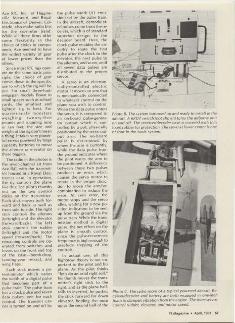
Photo B. Th e system buttoned up and ready to install in the<br />
aircra ft. A 6PD T switch (not shown] turns the airborne unit<br />
on and o ff. The receiver/decoder case is covered with thin<br />
foam rubber for protection. Th e servo at lo wer center is one<br />
o f fo ur in the basic system.<br />
Photo C. The rad io room o f a t yp ical powered aircraft. Re-<br />
ceiver/decoder and battery are both wrapped in one-inch<br />
foam to dampen vibration from the engine. The three servos<br />
control rudder. elevator. and motor speed.<br />
-<br />
73 Magazine · April, 1981 57


