

DID TEURS
MagaZine - Free and Open Source Software
MagaZine - Free and Open Source Software
- No tags were found...

Create successful ePaper yourself
Turn your PDF publications into a flip-book with our unique Google optimized e-Paper software.
so lde r one end terminal and<br />
the arm toge ther. Then<br />
sol d e r ab out 3/ 4- i nc h<br />
lengths of wire to eac h end<br />
terminal. Bend the leads<br />
strai ght back from the front<br />
of the pot and set it aside<br />
for a few m oments.<br />
Pu II the bottom cover off<br />
the rig to expose the transmitter<br />
circuit board . R1 34 is<br />
located behi nd the deviation<br />
pot. (See Fig. 2.) Snip<br />
the resistor in half, crush<br />
the ca rbon and composition<br />
from the leads, and<br />
bend the leads straight up.<br />
Now solder the leads from<br />
the pot to the leads protruding<br />
from the circuit<br />
board. Be carefu l - not too<br />
much heat-you don't<br />
want the so lder to flow on<br />
the foil side of the board.<br />
To adjust the pot, set it<br />
for about SOOk and get into<br />
a QSO on a Pl -controlled<br />
repeater. Sl ightly increase<br />
the res is tance o n each<br />
transmissi o n. When t he<br />
other stations report that<br />
they ca n no longer hear the<br />
tone, note the position, but<br />
continue increasin g the resista<br />
nce until you ca n no<br />
longer hold the machi ne.<br />
Then set the pot midway<br />
between those two points.<br />
If you fi nd that you ca n no<br />
longer hold the m achine<br />
w hile the tone is sti ll audib<br />
le, chec k the frequen cy of<br />
the tone.<br />
As long as you have the<br />
rig on the benc h, you m ay<br />
as well consider o ne other<br />
simple m od . M y ri g is in and<br />
out of the car severa l times<br />
a day. A t that rate, it d id n't<br />
take long for the p hone<br />
plug coax connector to bec<br />
o m e l o o se a nd interm<br />
ittent. After taking the rig<br />
apart several times to<br />
tighten up the con nector, it<br />
finally dawned o n me that<br />
there must be a better way.<br />
O ne way would be to replace<br />
the phono jack with a<br />
chassis-mount BN C connector.<br />
That would requ ire<br />
some (slight) mechanical rew<br />
ork of the box, however.<br />
Since m y mechanical ability<br />
is zero-I can't even put<br />
the ca p o n a peanut butter<br />
jar witho ut getting it crossthreaded-I<br />
began considering<br />
alternative so lutions.<br />
I decided that a short piece<br />
of coax and a few connectors<br />
could do the trick.<br />
For m ost practical purposes,<br />
the input and output<br />
characteristics of a halfwave<br />
sec tion of coax are<br />
the same. If you were to<br />
solder a half-wave section<br />
of coax to the o ut put of the<br />
rig, you w ould effectively<br />
move the outpu t point to<br />
the end of t he coax. That is<br />
the theory.<br />
To pu t theory into practice,<br />
sol der a UG-89/U BNC<br />
connector to one end of a<br />
piece of so l id-d ie lect ric<br />
RG-S8. O n the other end,<br />
solder a phono<br />
plug. The<br />
distance from the open end<br />
of the UC-89 to t he tip of<br />
the phono plug sho uld be<br />
24-1/2 inches.<br />
Now, tack so lder the<br />
phone plug to the antenna<br />
connector on the rig. I emphasiz<br />
e tack solder, beca<br />
use you may eventually<br />
have to take the rig apart<br />
f or m a intenance, and a<br />
completely so ldered co n<br />
nection would be a bea r to<br />
get apart.<br />
Replace the phone plugs<br />
in your ca r or shack, o r<br />
wherever else you operate,<br />
with UC-88fU connectors;<br />
you' ll be back in business<br />
"LOOK"<br />
THIS BIG G IS THE<br />
SYMBOL OF<br />
METROLINA'S FASTEST<br />
GROWING HAM DEALER<br />
(803)366-7157<br />
800-845-6~83<br />
D<br />
G.I.S.M.O.<br />
2305 CHERRY ROAD<br />
ROCK HILL, S.C. 29730<br />
w ithout in termittent coax<br />
connectors.<br />
There are seve ral other<br />
mods w hi ch I would l ike to<br />
describe in futu re artic les.<br />
D<br />
Service Department<br />
Call 803-366-1158<br />
In the meantime, you ca n<br />
en joy operation w it hout<br />
interm ittent coax connector<br />
s a n d w ithout t he<br />
hum.•<br />
DO<br />
DO<br />
D<br />
([J: 9 P<br />
ro.<br />
....R T Of ~'--"L-~ _<br />
"'" ~<br />
1:<br />
r<br />
n • •<br />
::::"<br />
,,~<br />
rH~~nT<br />
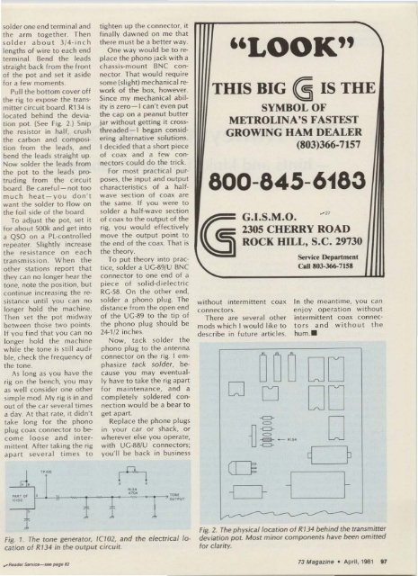
Fig. 1. The tone generator, 1(102, and the electrical I~<br />
cation of R134 in the output circuit.<br />
..<br />
-1 ~ 1_~<br />
Fig. 2. The physical/ocation o f R134 behind the transmitter<br />
de viation pot. Most minor components have been omitted<br />
for clarit y.<br />
73 Magazine · April, 1981 97


