
You also want an ePaper? Increase the reach of your titles
YUMPU automatically turns print PDFs into web optimized ePapers that Google loves.
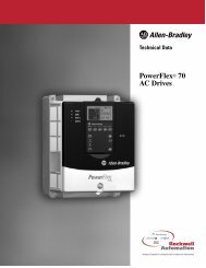
www.abpowerflex.com<br />
Adjustable<br />
Frequency AC<br />
Drive<br />
FRN 1.xx<br />
User Manual
Important User Information<br />
Solid state equipment has operational characteristics differing from those of<br />
electromechanical equipment. Safety Guidelines for the Application, Installation<br />
and Maintenance of Solid State Controls (Publication SGI-1.1 available from your<br />
local Rockwell Automation sales office or online at<br />
http://www.rockwellautomation.com/literature) describes some important<br />
differences between solid state equipment and hard-wired electromechanical<br />
devices. Because of this difference, and also because of the wide variety of uses for<br />
solid state equipment, all persons responsible for applying this equipment must<br />
satisfy themselves that each intended application of this equipment is acceptable.<br />
In no event will Rockwell Automation, Inc. be responsible or liable for indirect or<br />
consequential damages resulting from the use or application of this equipment.<br />
The examples and diagrams in this manual are included solely for illustrative<br />
purposes. Because of the many variables and requirements associated with any<br />
particular installation, Rockwell Automation, Inc. cannot assume responsibility or<br />
liability for actual use based on the examples and diagrams.<br />
No patent liability is assumed by Rockwell Automation, Inc. with respect to use of<br />
information, circuits, equipment, or software described in this manual.<br />
Reproduction of the contents of this manual, in whole or in part, without written<br />
permission of Rockwell Automation, Inc. is prohibited.<br />
Throughout this manual, when necessary we use notes to make you aware of safety<br />
considerations.<br />
WARNING: Identifies information about practices or circumstances<br />
that can cause an explosion in a hazardous environment, which may<br />
lead to personal injury or death, property damage, or economic loss.<br />
Important: Identifies information that is critical for successful application and<br />
understanding of the product.<br />
ATTENTION: Identifies information about practices or circumstances<br />
that can lead to personal injury or death, property damage, or economic<br />
loss. Attentions help you:<br />
• identify a hazard<br />
• avoid the hazard<br />
• recognize the consequences<br />
Shock Hazard labels may be located on or inside the equipment (e.g.,<br />
drive or motor) to alert people that dangerous voltage may be present.<br />
Burn Hazard labels may be located on or inside the equipment (e.g.,<br />
drive or motor) to alert people that surfaces may be at dangerous<br />
temperatures.<br />
PowerFlex is a registered trademark of Rockwell Automation, Inc.<br />
DriveExplorer, DriveExecutive, and SCANport are trademarks of Rockwell Automation, Inc.<br />
PLC is a registered trademark of Rockwell Automation, Inc.
Preface Overview<br />
Chapter 1 Installation/Wiring<br />
Chapter 2 Start Up<br />
Table of Contents<br />
Who Should Use this Manual? . . . . . . . . . P-1<br />
Reference Materials . . . . . . . . . . . . . . . . . P-1<br />
Manual Conventions . . . . . . . . . . . . . . . . . P-2<br />
Drive Frame Sizes . . . . . . . . . . . . . . . . . . . P-2<br />
General Precautions . . . . . . . . . . . . . . . . . P-3<br />
Catalog Number Explanation . . . . . . . . . . P-4<br />
Opening the Cover . . . . . . . . . . . . . . . . . . 1-1<br />
Mounting Considerations . . . . . . . . . . . . . 1-2<br />
AC Supply Source Considerations . . . . . . 1-3<br />
General Grounding Requirements . . . . . . 1-5<br />
Fuses and Circuit Breakers . . . . . . . . . . . . 1-7<br />
Power Wiring . . . . . . . . . . . . . . . . . . . . . . 1-9<br />
I/O Wiring Recommendations . . . . . . . . 1-13<br />
Start and Speed Reference Control . . . . . 1-19<br />
EMC Instructions . . . . . . . . . . . . . . . . . . 1-21<br />
Prepare For Drive Start-Up . . . . . . . . . . . . 2-1<br />
Integral Keypad . . . . . . . . . . . . . . . . . . . . . 2-3<br />
Viewing and Editing Parameters . . . . . . . . 2-4<br />
Chapter 3 Programming and Parameters<br />
About Parameters . . . . . . . . . . . . . . . . . . . 3-1<br />
Parameter Organization. . . . . . . . . . . . . . . 3-2<br />
Display Group . . . . . . . . . . . . . . . . . . . . . . 3-3<br />
Basic Program Group . . . . . . . . . . . . . . . . 3-8<br />
Terminal Block Group. . . . . . . . . . . . . . . 3-13<br />
Communications Group . . . . . . . . . . . . . 3-17<br />
Advanced Program Group. . . . . . . . . . . . 3-19<br />
Parameter Cross Reference – by Name. . 3-31<br />
Chapter 4 Troubleshooting<br />
Drive Status. . . . . . . . . . . . . . . . . . . . . . . . 4-1<br />
Faults. . . . . . . . . . . . . . . . . . . . . . . . . . . . . 4-1<br />
Fault Descriptions . . . . . . . . . . . . . . . . . . . 4-3<br />
Common Symptoms and<br />
Corrective Actions . . . . . . . . . . . . . . . . 4-5<br />
Appendix A Supplemental Drive Information<br />
Drive, Fuse & Circuit Breaker Ratings . . . A-1<br />
Specifications . . . . . . . . . . . . . . . . . . . . . . A-2<br />
Appendix B Accessories and Dimensions<br />
Product Selection . . . . . . . . . . . . . . . . . . . B-1<br />
Product Dimensions . . . . . . . . . . . . . . . . . B-6
ii<br />
Appendix C <strong>RS485</strong> (<strong>DSI</strong>) <strong>Protocol</strong><br />
Network Wiring . . . . . . . . . . . . . . . . . . . . . C-1<br />
Parameter Configuration . . . . . . . . . . . . . . C-2<br />
Supported Modbus Function Codes . . . . . C-2<br />
Writing (06) Logic Command Data. . . . . . C-3<br />
Writing (06) Reference . . . . . . . . . . . . . . . C-4<br />
Reading (03) Logic Status Data. . . . . . . . . C-4<br />
Reading (03) Feedback . . . . . . . . . . . . . . . C-4<br />
Reading (03) Drive Error Codes . . . . . . . . C-5<br />
Reading (03) and Writing (06)<br />
Drive Parameters . . . . . . . . . . . . . . . . . C-5<br />
Additional Information . . . . . . . . . . . . . . . C-5<br />
Appendix D RJ45 <strong>DSI</strong> Splitter Cable<br />
Connectivity Guidelines . . . . . . . . . . . . . . D-1<br />
<strong>DSI</strong> Cable Accessories . . . . . . . . . . . . . . . D-2<br />
Connecting an RS-485 Network . . . . . . . . D-3<br />
Index
Overview<br />
Preface<br />
The purpose of this manual is to provide you with the basic information<br />
needed to install, start-up and troubleshoot the PowerFlex 4M<br />
Adjustable Frequency AC Drive.<br />
For information on… See page…<br />
Who Should Use this Manual? P-1<br />
Reference Materials P-1<br />
Manual Conventions P-2<br />
Drive Frame Sizes P-2<br />
General Precautions P-3<br />
Catalog Number Explanation P-4<br />
Who Should Use this Manual?<br />
This manual is intended for qualified personnel. You must be able to<br />
program and operate Adjustable Frequency AC Drive devices. In<br />
addition, you must have an understanding of the parameter settings and<br />
functions.<br />
Reference Materials<br />
The following manuals are recommended for general drive information:<br />
Title Publication Available Online at …<br />
Wiring and Grounding<br />
Guidelines for Pulse Width<br />
Modulated (PWM) AC Drives<br />
DRIVES-IN001…<br />
Preventive Maintenance of<br />
Industrial Control and Drive<br />
System Equipment<br />
DRIVES-SB001…<br />
Safety Guidelines for the SGI-1.1 www.rockwellautomation.com/<br />
Application, Installation and<br />
Maintenance of Solid State<br />
Control<br />
literature<br />
A Global Reference Guide for<br />
Reading Schematic Diagrams<br />
0100-2.10<br />
Guarding Against Electrostatic<br />
Damage<br />
8000-4.5.2
P-2 Overview<br />
Manual Conventions<br />
• In this manual we refer to the PowerFlex 4M Adjustable Frequency<br />
AC Drive as: drive, PowerFlex 4M or PowerFlex 4M Drive.<br />
• Parameter numbers and names are shown in this format:<br />
P101 [Motor NP Volts]<br />
Name<br />
Number<br />
Group<br />
d = Display Group<br />
P = Basic Program Group<br />
t = Terminal Block Group<br />
C = Communications Group<br />
A = Advanced Program Group<br />
• The following words are used throughout the manual to describe an<br />
action:<br />
Word Meaning<br />
Can Possible, able to do something<br />
Cannot Not possible, not able to do something<br />
May Permitted, allowed<br />
Must Unavoidable, you must do this<br />
Shall Required and necessary<br />
Should Recommended<br />
Should Not Not Recommended<br />
Drive Frame Sizes<br />
Similar PowerFlex 4M drive sizes are grouped into frame sizes to<br />
simplify spare parts ordering, dimensioning, etc. A cross-reference of<br />
drive catalog numbers and their respective frame sizes is provided in<br />
Appendix B.
!<br />
!<br />
!<br />
!<br />
!<br />
General Precautions<br />
Overview P-3<br />
ATTENTION: To avoid an electric shock hazard, verify that the<br />
voltage on the bus capacitors has discharged before performing any<br />
work on the drive. Measure the DC bus voltage at the –DC and +DC<br />
terminals on the Power Terminal Block (refer to Chapter 1 Power<br />
Terminal descriptions). The voltage must be zero.<br />
Darkened LEDs or a darkened LCD display is not an indication that<br />
capacitors have discharged to safe voltage levels.<br />
ATTENTION: Only qualified personnel familiar with adjustable<br />
frequency AC drives and associated machinery should plan or<br />
implement the installation, start-up and subsequent maintenance of the<br />
system. Failure to comply may result in personal injury and/or<br />
equipment damage.<br />
ATTENTION: This drive contains ESD (Electrostatic Discharge)<br />
sensitive parts and assemblies. Static control precautions are required<br />
when installing, testing, servicing or repairing this assembly.<br />
Component damage may result if ESD control procedures are not<br />
followed. If you are not familiar with static control procedures,<br />
reference A-B publication 8000-4.5.2, “Guarding Against Electrostatic<br />
Damage” or any other applicable ESD protection handbook.<br />
ATTENTION: An incorrectly applied or installed drive can result in<br />
component damage or a reduction in product life. Wiring or application<br />
errors, such as, undersizing the motor, incorrect or inadequate AC<br />
supply, or excessive ambient temperatures may result in malfunction of<br />
the system.<br />
ATTENTION: The bus regulator function is extremely useful for<br />
preventing nuisance overvoltage faults resulting from aggressive<br />
decelerations, overhauling loads, and eccentric loads. However, it can<br />
also cause either of the following two conditions to occur.<br />
1. Fast positive changes in input voltage or imbalanced input voltages<br />
can cause uncommanded positive speed changes;<br />
2. Actual deceleration times can be longer than commanded<br />
deceleration times.<br />
However, a “Stall Fault” is generated if the drive remains in this state<br />
for 1 minute. If this condition is unacceptable, the bus regulator must be<br />
disabled (see parameter A441). In addition, installing a properly sized<br />
dynamic brake resistor will provide equal or better performance in most<br />
cases.
P-4 Overview<br />
Catalog Number Explanation<br />
1-3 4 5 6-8 9 10 11 12 13-14<br />
22F - D 8P7 N 1 1 3 AA<br />
Drive Dash Voltage Rating Rating Enclosure HIM Emission Class Type Optional<br />
Code<br />
22F PowerFlex 4M<br />
Code Voltage Ph.<br />
V 120V AC 1<br />
A 240V AC 1<br />
B 240V AC 3<br />
D 480V AC 3<br />
Output Current @ 100-120V Input<br />
Code Amps kW (HP)<br />
1P6 1.6 0.2 (0.25)<br />
2P5 2.5 0.4 (0.5)<br />
4P5 4.5 0.75 (1.0)<br />
6P0 6.0 1.1 (1.5)<br />
Code Interface Module<br />
1 Fixed Keypad<br />
Code Version<br />
3 No Brake IGBT<br />
4 Standard<br />
Code Enclosure<br />
N Panel Mount - IP 20 (NEMA Type Open)<br />
Output Current @ 200-240V Input<br />
Code Amps kW (HP)<br />
1P6 1.6 0.2 (0.25)<br />
2P5 2.5 0.4 (0.5)<br />
4P2 4.2 0.75 (1.0)<br />
8P0 8.0 1.5 (2.0)<br />
011 11.0 2.2 (3.0)<br />
012 12.0 2.2 (3.0)<br />
017 17.5 3.7 (5.0)<br />
025 25.0 5.5 (7.5)<br />
033 33.0 7.5 (10.0)<br />
Code Rating<br />
0 Not Filtered<br />
1 Filtered<br />
Code Purpose<br />
AA Reserved for<br />
thru custom firmware<br />
ZZ<br />
Output Current @ 380-480V Input<br />
Code Amps kW (HP)<br />
1P5 1.5 0.4 (0.5)<br />
2P5 2.5 0.75 (1.0)<br />
4P2 4.2 1.5 (2.0)<br />
6P0 6.0 2.2 (3.0)<br />
8P7 8.7 3.7 (5.0)<br />
013 13.0 5.5 (7.5)<br />
018 18.0 7.5 (10.0)<br />
024 24.0 10.0 (15.0)<br />
Additional accessories, options and adapters are available. See Appendix B for details.
!<br />
Installation/Wiring<br />
This chapter provides information on mounting and wiring the<br />
PowerFlex 4M Drive.<br />
Chapter 1<br />
For information on… See page For information on… See page<br />
Opening the Cover 1-1 Fuses and Circuit Breakers 1-7<br />
Mounting Considerations 1-2 Power Wiring 1-9<br />
AC Supply Source Considerations 1-3 I/O Wiring<br />
Recommendations<br />
1-13<br />
General Grounding Requirements 1-5 EMC Instructions 1-21<br />
Most start-up difficulties are the result of incorrect wiring. Every<br />
precaution must be taken to assure that the wiring is done as instructed.<br />
All items must be read and understood before the actual installation<br />
begins.<br />
ATTENTION: The following information is merely a guide for proper<br />
installation. Rockwell Automation, Inc. cannot assume responsibility<br />
for the compliance or the noncompliance to any code, national, local or<br />
otherwise for the proper installation of this drive or associated<br />
equipment. A hazard of personal injury and/or equipment damage<br />
exists if codes are ignored during installation.<br />
Opening the Cover<br />
1. Press and hold in the tabs on each side of the cover.<br />
2. Pull the cover out and up to release.
1-2 Installation/Wiring<br />
Mounting Considerations<br />
• Mount the drive upright on a flat, vertical and level surface.<br />
– Install on 35 mm DIN Rail (for frames A and B).<br />
or<br />
– Install with screws.<br />
Table 1.A Screw Mounting Recommendations<br />
Minimum Panel Thickness Screw Size Mounting Torque<br />
1.9 mm (0.0747 in.) M4 (#8-32) 1.56-1.96 N-m (14-17 lb.-in.)<br />
• Protect the cooling fan by avoiding dust or metallic particles.<br />
• Do not expose to a corrosive atmosphere.<br />
• Protect from moisture and direct sunlight.<br />
Minimum Mounting Clearances<br />
Refer to Appendix B for mounting dimensions.<br />
Airflow<br />
Closest object that<br />
may obstruct air flow<br />
through the drive<br />
heat sink and chassis<br />
Ambient Operating Temperatures<br />
Table 1.B Enclosure and Clearance Requirements<br />
Horizontal Clearance between drives<br />
Ambient Temperature<br />
Minimum Maximum<br />
0 mm and greater -10°C (14°F) 40°C (104°F)<br />
25 mm and greater -10°C (14°F) 50°C (122°F)<br />
Drive enclosure is rated IP20, NEMA/UL Type Open.<br />
See Table 1.B<br />
76.2 mm (3.0 in.)<br />
76.2 mm (3.0 in.)<br />
76.2 mm (3.0 in.)<br />
76.2 mm (3.0 in.)
!<br />
Installation/Wiring 1-3<br />
Storage<br />
• Store within an ambient temperature range of -40° to +85°C.<br />
• Store within a relative humidity range of 0% to 95%,<br />
non-condensing.<br />
• Do not expose to a corrosive atmosphere.<br />
AC Supply Source Considerations<br />
Ungrounded Distribution Systems<br />
ATTENTION: PowerFlex 4M drives contain protective MOVs that<br />
are referenced to ground. These devices must be disconnected if the<br />
drive is installed on an ungrounded or resistive grounded distribution<br />
system.<br />
Disconnecting MOVs<br />
To prevent drive damage, the MOVs connected to ground shall be<br />
disconnected if the drive is installed on an ungrounded distribution<br />
system where the line-to-ground voltages on any phase could exceed<br />
125% of the nominal line-to-line voltage. To disconnect these devices,<br />
remove the jumper shown in the Figures 1.1 and 1.2.<br />
1. Turn the screw counterclockwise to loosen.<br />
2. Pull the jumper completely out of the drive chassis.<br />
3. Tighten the screw to keep it in place.<br />
Figure 1.1 Jumper Location (Frame A shown)<br />
Important:<br />
Tighten screw after<br />
jumper removal.
1-4 Installation/Wiring<br />
Figure 1.2 Phase to Ground MOV Removal<br />
Input Power Conditioning<br />
The drive is suitable for direct connection to input power within the rated<br />
voltage of the drive (see Appendix A). Listed in Table 1.C are certain<br />
input power conditions which may cause component damage or<br />
reduction in product life. If any of the conditions exist, as described in<br />
Table 1.C, install one of the devices listed under the heading Corrective<br />
Action on the line side of the drive.<br />
Important: Only one device per branch circuit is required. It should be<br />
mounted closest to the branch and sized to handle the total<br />
current of the branch circuit.<br />
Table 1.C Input Power Conditions<br />
Input Power Condition Corrective Action<br />
Low Line Impedance (less than 1% line reactance) • Install Line Reactor (1)<br />
Greater than 120 kVA supply transformer<br />
• or Isolation Transformer<br />
Line has power factor correction capacitors<br />
Line has frequent power interruptions<br />
Three-Phase<br />
AC Input<br />
Line has intermittent noise spikes in excess of<br />
6000V (lightning)<br />
Phase to ground voltage exceeds 125% of normal<br />
line to line voltage<br />
Ungrounded distribution system<br />
R/L1<br />
S/L2<br />
T/L3<br />
(1) Refer to Appendix B for accessory ordering information.<br />
Jumper<br />
1 2 3 4<br />
• Remove MOV jumper to ground.<br />
• or Install Isolation Transformer<br />
with grounded secondary if<br />
necessary.
General Grounding Requirements<br />
Installation/Wiring 1-5<br />
The drive Safety Ground - (PE) must be connected to system ground.<br />
Ground impedance must conform to the requirements of national and<br />
local industrial safety regulations and/or electrical codes. The integrity<br />
of all ground connections should be periodically checked.<br />
Figure 1.3 Typical Grounding<br />
R/L1<br />
S/L2<br />
T/L3<br />
Ground Fault Monitoring<br />
If a system ground fault monitor (RCD) is to be used, only Type B<br />
(adjustable) devices should be used to avoid nuisance tripping.<br />
Safety Ground - (PE)<br />
This is the safety ground for the drive that is required by code. One of<br />
these points must be connected to adjacent building steel (girder, joist), a<br />
floor ground rod or bus bar. Grounding points must comply with national<br />
and local industrial safety regulations and/or electrical codes.<br />
Motor Ground<br />
SHLD<br />
U/T1<br />
V/T2<br />
W/T3<br />
The motor ground must be connected to one of the ground terminals on<br />
the drive.
1-6 Installation/Wiring<br />
Shield Termination - SHLD<br />
Either of the safety ground terminals located on the power terminal<br />
block provides a grounding point for the motor cable shield. The motor<br />
cable shield connected to one of these terminals (drive end) should also<br />
be connected to the motor frame (motor end). Use a shield terminating or<br />
EMI clamp to connect the shield to the safety ground terminal. The<br />
conduit box option may be used with a cable clamp for a grounding point<br />
for the cable shield.<br />
When shielded cable is used for control and signal wiring, the shield<br />
should be grounded at the source end only, not at the drive end.<br />
RFI Filter Grounding<br />
Using single phase drives with integral filter, or an external filter with<br />
any drive rating, may result in relatively high ground leakage currents.<br />
Therefore, the filter must only be used in installations with grounded<br />
AC supply systems and be permanently installed and solidly<br />
grounded (bonded) to the building power distribution ground. Ensure<br />
that the incoming supply neutral is solidly connected (bonded) to the<br />
same building power distribution ground. Grounding must not rely on<br />
flexible cables and should not include any form of plug or socket that<br />
would permit inadvertent disconnection. Some local codes may require<br />
redundant ground connections. The integrity of all connections should be<br />
periodically checked.
!<br />
Fuses and Circuit Breakers<br />
Installation/Wiring 1-7<br />
The PowerFlex 4M does not provide branch short circuit protection. This<br />
product should be installed with either input fuses or an input circuit<br />
breaker. National and local industrial safety regulations and/or electrical<br />
codes may determine additional requirements for these installations.<br />
ATTENTION: To guard against personal injury and/or equipment<br />
damage caused by improper fusing or circuit breaker selection, use only<br />
the recommended line fuses/circuit breakers specified in this section.<br />
Fusing<br />
The PowerFlex 4M has been UL tested and approved for use with input<br />
fuses. The ratings in the table that follows are the maximum<br />
recommended values for use with each drive rating. The devices listed in<br />
this table are provided to serve as a guide.<br />
Bulletin 140M (Self-Protected Combination Controller)/UL489<br />
Circuit Breakers<br />
When using Bulletin 140M or UL489 rated circuit breakers, the<br />
guidelines listed below must be followed in order to meet the NEC<br />
requirements for branch circuit protection.<br />
• Bulletin 140M can be used in single and group motor applications.<br />
• Bulletin 140M can be used up stream from the drive without the<br />
need for fuses.
1-8 Installation/Wiring<br />
Table 1.D Minimum Recommended Branch Circuit Protective Devices<br />
Voltage<br />
Rating<br />
120V AC –<br />
1-Phase<br />
240V AC –<br />
1-Phase<br />
240V AC –<br />
3-Phase<br />
480V AC –<br />
3-Phase<br />
Drive Rating<br />
kW (HP)<br />
0.2 (0.25)<br />
0.4 (0.5)<br />
0.75 (1.0)<br />
1.1 (1.5)<br />
0.2 (0.25)<br />
0.4 (0.5)<br />
0.75 (1.0)<br />
1.5 (2.0)<br />
2.2 (3.0)<br />
0.2 (0.25)<br />
0.4 (0.5)<br />
0.75 (1.0)<br />
1.5 (2.0)<br />
2.2 (3.0)<br />
3.7 (5.0)<br />
5.5 (7.5)<br />
7.5 (10.0)<br />
0.4 (0.5)<br />
0.75 (1.0)<br />
1.5 (2.0)<br />
2.2 (3.0)<br />
3.7 (5.0)<br />
5.5 (7.5)<br />
7.5 (10.0)<br />
11.0 (15.0)<br />
Fuse Rating (1)<br />
Amps<br />
10<br />
15<br />
30<br />
40<br />
10<br />
10<br />
15<br />
35<br />
40<br />
3<br />
6<br />
10<br />
15<br />
25<br />
35<br />
45<br />
60<br />
3<br />
6<br />
10<br />
10<br />
15<br />
25<br />
30<br />
50<br />
140M (2)<br />
Catalog No.<br />
140M-C2E-C10<br />
140M-C2E-C16<br />
140M-D8E-C20<br />
140M-F8E-C32<br />
140M-C2E-B63<br />
140M-C2E-C10<br />
140M-C2E-C16<br />
140M-D8E-C25<br />
140M-F8E-C32<br />
140M-C2E-B25<br />
140M-C2E-B40<br />
140M-C2E-B63<br />
140M-C2E-C16<br />
140M-D8E-C20<br />
140M-F8E-C25<br />
140M-F8E-C32<br />
140M-F8E-C45<br />
140M-C2E-B25<br />
140M-C2E-B40<br />
140M-C2E-C10<br />
140M-C2E-C10<br />
140M-C2E-C16<br />
140M-D8E-C20<br />
140M-F8E-C25<br />
140M-F8E-C32<br />
Recommended<br />
MCS Contactors<br />
Catalog No.<br />
100-C09<br />
100-C12<br />
100-C23<br />
100-C30<br />
100-C09<br />
100-C09<br />
100-C12<br />
100-C23<br />
100-C30<br />
100-C09<br />
100-C09<br />
100-C09<br />
100-C12<br />
100-C23<br />
100-C23<br />
100-C37<br />
100-C60<br />
100-C09<br />
100-C09<br />
100-C09<br />
100-C09<br />
100-C12<br />
100-C23<br />
100-C23<br />
100-C30<br />
(1) Recommended Fuse Type: UL Class J, RK1, T or Type BS88; 600V (550V) or<br />
equivalent.<br />
(2)<br />
Refer to the selection guide for Bulletin 140M motor protectors for AIC ratings suitable<br />
for your particular application.
!<br />
!<br />
Power Wiring<br />
Installation/Wiring 1-9<br />
ATTENTION: National Codes and standards (NEC, VDE, BSI, etc.)<br />
and local codes outline provisions for safely installing electrical<br />
equipment. Installation must comply with specifications regarding wire<br />
types, conductor sizes, branch circuit protection and disconnect<br />
devices. Failure to do so may result in personal injury and/or equipment<br />
damage.<br />
ATTENTION: To avoid a possible shock hazard caused by induced<br />
voltages, unused wires in the conduit must be grounded at both ends.<br />
For the same reason, if a drive sharing a conduit is being serviced or<br />
installed, all drives using this conduit should be disabled. This will help<br />
minimize the possible shock hazard from “cross coupled” power leads.<br />
Motor Cable Types Acceptable for 200-600 Volt Installations<br />
General<br />
A variety of cable types are acceptable for drive installations. For many<br />
installations, unshielded cable is adequate, provided it can be separated<br />
from sensitive circuits. As an approximate guide, allow a spacing of 0.3<br />
meters (1 foot) for every 10 meters (32.8 feet) of length. In all cases,<br />
long parallel runs must be avoided. Do not use cable with an insulation<br />
thickness less than 15 mils (0.4 mm/0.015 in.). Do not route more than<br />
three sets of motor leads in a single conduit to minimize “cross talk”. If<br />
more than three drive/motor connections per conduit are required,<br />
shielded cable must be used.<br />
UL installations in 50°C ambient must use 600V, 75°C or 90°C wire.<br />
UL installations in 40°C ambient should use 600V, 75°C or 90°C wire.<br />
Use copper wire only. Wire gauge requirements and recommendations<br />
are based on 75 degree C. Do not reduce wire gauge when using higher<br />
temperature wire.<br />
Unshielded<br />
THHN, THWN or similar wire is acceptable for drive installation in dry<br />
environments provided adequate free air space and/or conduit fill rates<br />
limits are provided. Do not use THHN or similarly coated wire in wet<br />
areas. Any wire chosen must have a minimum insulation thickness of<br />
15 mils and should not have large variations in insulation concentricity.
1-10 Installation/Wiring<br />
Location<br />
Shielded<br />
Rating/Type Description<br />
Standard 600V, 75°C or 90°C (167°F • Four tinned copper conductors with XLPE insulation<br />
(Option 1) or 194°F) RHH/RHW-2 • Foil shield and tinned copper drain wire with 85% braid<br />
Belden 29501-29507 or coverage<br />
equivalent<br />
• PVC jacket<br />
Standard Tray rated 600V, 75°C or • Three tinned copper conductors with XLPE insulation<br />
(Option 2) 90°C (167°F or 194°F)<br />
RHH/RHW-2<br />
• 5 mil single helical copper tape (25% overlap min.)<br />
with three bare copper grounds in contact with shield<br />
Shawflex 2ACD/3ACD or<br />
equivalent<br />
• PVC jacket<br />
Class I & II; Tray rated 600V, 75°C or • Three tinned copper conductors with XLPE insulation<br />
Division I & II 90°C (167°F or 194°F)<br />
RHH/RHW-2<br />
• 5 mil single helical copper tape (25% overlap min.)<br />
with three bare copper grounds in contact with shield<br />
• PVC copper grounds on #10 AWG and smaller<br />
Reflected Wave Protection<br />
The drive should be installed as close to the motor as possible.<br />
Installations with long motor cables may require the addition of external<br />
devices to limit voltage reflections at the motor (reflected wave<br />
phenomena). See Table 1.E for recommendations.<br />
The reflected wave data applies to all frequencies 2 to 10 kHz.<br />
For 240V ratings, reflected wave effects do not need to be considered.<br />
Table 1.E Maximum Cable Length Recommendations<br />
Reflected Wave<br />
380-480V Ratings Motor Insulation Rating Motor Cable Only (1)<br />
(1) Longer cable lengths can be achieved by installing devices on the output of the drive.<br />
Consult factory for recommendations.<br />
Output Disconnect<br />
1000 Vp-p 15 meters (49 feet)<br />
1200 Vp-p 40 meters (131 feet)<br />
1600 Vp-p 170 meters (558 feet)<br />
The drive is intended to be commanded by control input signals that will<br />
start and stop the motor. A device that routinely disconnects then<br />
reapplies output power to the motor for the purpose of starting and<br />
stopping the motor should not be used. If it is necessary to disconnect<br />
power to the motor with the drive outputting power, an auxiliary contact<br />
should be used to simultaneously disable drive control run commands.
Power Terminal Block<br />
Installation/Wiring 1-11<br />
The drive utilizes a finger guard over the power wiring terminals.<br />
To remove:<br />
1. Press in and hold the locking tab.<br />
2. For the finger guard on the top of the drive, slide it down and out.<br />
For the finger guard at the bottom of the drive, slide it up and out.<br />
Replace the finger guard when wiring is complete.<br />
Figure 1.4 Power Terminal Block<br />
Frame A and B<br />
R/L1 S/L2 T/L3<br />
Frame C<br />
R/L1 S/L2 T/L3 P1 P2<br />
Frame A and B<br />
U/T1 V/T2 W/T3 DC+ DC-<br />
Frame C<br />
BR+<br />
U/T1 V/T2 W/T3 DC+ BR- DC-<br />
Terminal Description<br />
R/L1, S/L2 1-Phase Input<br />
R/L1, S/L2, T/L3 3-Phase Input<br />
P1 (1) , P2 (1)<br />
DC Bus Inductor Connection (Frame C drives only.)<br />
The Frame C drive is shipped with a jumper between Terminals P1<br />
and P2. Remove this jumper only when a DC Bus Inductor will be<br />
connected. Drive will not power up without a jumper or inductor<br />
connected.<br />
U/T1 To Motor U/T1<br />
Switch any two motor<br />
V/T2<br />
W/T3<br />
To Motor V/T2<br />
To Motor W/T3<br />
=<br />
leads to change forward<br />
direction.
1-12 Installation/Wiring<br />
DC+ (2) , DC- (2) DC Bus Connection<br />
BR+ (1) , BR- (1) Terminal Description<br />
Dynamic Brake Resistor Connection<br />
Safety Ground - PE<br />
(1) For Frame C only [5.5 kW (7.5 HP) ratings and higher].<br />
(2) Not applicable to 120 V, 1-Phase drives.<br />
!<br />
!<br />
Table 1.F Power Terminal Block Specifications<br />
Frame Maximum Wire Size (1)<br />
Minimum Wire Size (1) Torque<br />
A 3.3 mm2 (12 AWG) 0.8 mm2 (18 AWG) 1.4-1.6 N-m (12-14 lb.-in.)<br />
B 8.4 mm2 (8 AWG) 0.8 mm2 (18 AWG) 1.6-1.9 N-m (14-17 lb.-in.)<br />
C 13.3 mm 2 (6 AWG) 3.3 mm 2 (12 AWG) 2.7-3.2 N-m (24-28 lb.-in.)<br />
(1) Maximum/minimum sizes that the terminal block will accept - these are not<br />
recommendations.<br />
Motor Start/Stop Precautions<br />
ATTENTION: A contactor or other device that routinely disconnects<br />
and reapplies the AC line to the drive to start and stop the motor can<br />
cause drive hardware damage. The drive is designed to use control input<br />
signals that will start and stop the motor. If used, the input device must<br />
not exceed one operation per minute or drive damage can occur.<br />
ATTENTION: The drive start/stop control circuitry includes<br />
solid-state components. If hazards due to accidental contact with<br />
moving machinery or unintentional flow of liquid, gas or solids exist,<br />
an additional hardwired stop circuit may be required to remove the AC<br />
line to the drive. When the AC line is removed, there will be a loss of<br />
any inherent regenerative braking effect that might be present - the<br />
motor will coast to a stop. An auxiliary braking method may be<br />
required.
!<br />
I/O Wiring Recommendations<br />
Important points to remember about I/O wiring:<br />
Installation/Wiring 1-13<br />
• Always use copper wire.<br />
• Wire with an insulation rating of 600V or greater is recommended.<br />
• Control and signal wires should be separated from power wires by at<br />
least 0.3 meters (1 foot).<br />
Important: I/O terminals labeled “Common” are not referenced to the<br />
safety ground (PE) terminal and are designed to greatly<br />
reduce common mode interference.<br />
ATTENTION: Driving the 4-20mA analog input from a voltage<br />
source could cause component damage. Verify proper configuration<br />
prior to applying input signals.<br />
Control Wire Types<br />
Table 1.G Recommended Control and Signal Wire (1)<br />
Wire Type(s) Description Minimum<br />
Insulation Rating<br />
Belden 8760/9460<br />
(or equiv.)<br />
Belden 8770<br />
(or equiv.)<br />
I/O Terminal Block<br />
0.8 mm2 (18 AWG), twisted pair, 100%<br />
shield with drain. (1)<br />
0.8 mm 2 (18 AWG), 3 conductor, shielded for<br />
remote pot only.<br />
300V<br />
60 degrees C<br />
(140 degrees F)<br />
(1) If the wires are short and contained within a cabinet which has no sensitive circuits,<br />
the use of shielded wire may not be necessary, but is always recommended.<br />
Table 1.H I/O Terminal Block Specifications<br />
Maximum Wire Size (1)<br />
Minimum Wire Size (1)<br />
Torque<br />
1.3 mm2 (16 AWG) 0.2 mm2 (24 AWG) 0.5-0.8 N-m (4.4-7 lb.-in.)<br />
(1) Maximum/minimum sizes that the terminal block will accept - these are not<br />
recommendations.<br />
Maximum Control Wire Recommendations<br />
Do not exceed control wiring length of 30 meters (100 feet). Control<br />
signal cable length is highly dependent on electrical environment and<br />
installation practices. To improve noise immunity, the I/O terminal block<br />
Common must be connected to ground terminal/protective earth. If using<br />
the <strong>RS485</strong> (<strong>DSI</strong>) port, I/O Terminal 16 should also be connected to<br />
ground terminal/protective earth.
1-14 Installation/Wiring<br />
Figure 1.5 Control Wiring Block Diagram<br />
(1)<br />
Important: I/O Terminal 01 is always a coast to stop input except<br />
when P106 [Start Source] is set to “3-Wire” control. In three wire<br />
control, I/O Terminal 01 is controlled by P107 [Stop Mode]. All other<br />
stop sources are controlled by P107 [Stop Mode].<br />
Important: The drive is shipped with a jumper installed between I/O<br />
Terminals 01 and 11. Remove this jumper when using I/O Terminal<br />
01 as a stop or enable input.<br />
(2)<br />
Two wire control shown. For three wire control use a momentary<br />
input on I/O Terminal 02 to command a start. Use a<br />
maintained input for I/O Terminal 03 to change direction.<br />
Potentiometer<br />
must be<br />
1-10k ohm<br />
2 Watt Min.<br />
No. Signal Default Description Param.<br />
R1 Relay N.O. Fault Normally open contact for output relay. t221<br />
R2 Relay Common – Common for output relay.<br />
R3 Relay N.C. Fault Normally closed contact for output relay. t221<br />
Sink/Source DIP Switch Source (SRC)<br />
01 Stop (1)<br />
Relay N.O.<br />
Relay Common<br />
Relay N.C.<br />
Coast<br />
R1<br />
R2<br />
R3<br />
02 Start/Run FWD Not Active<br />
03 Direction/Run REV Not Active<br />
SNK<br />
SRC<br />
R1 R2 R3<br />
Inputs can be wired as Sink (SNK) or Source (SRC) via DIP Switch<br />
setting.<br />
The factory installed jumper or a normally closed input<br />
must be present for the drive to start.<br />
Command comes from the integral keypad by default. To<br />
disable reverse operation, see A095 [Reverse Disable].<br />
04 Digital Common –<br />
For digital inputs. Electronically isolated with digital inputs<br />
from analog I/O.<br />
05 Digital Input 1 Preset Freq Program with t201 [Digital In1 Sel]. t201<br />
06 Digital Input 2 Preset Freq Program with t202 [Digital In2 Sel]. t202<br />
11 +24V DC –<br />
Drive supplied power for digital inputs.<br />
Maximum output current is 100mA.<br />
SNK<br />
+24V<br />
+10V<br />
01<br />
02<br />
03<br />
04<br />
05<br />
06<br />
11<br />
12<br />
13<br />
14<br />
15<br />
16<br />
Stop (1)<br />
Start/Run FWD (2)<br />
Direction/Run REV<br />
Digital Common<br />
Digital Input 1<br />
Digital Input 2<br />
+24V DC<br />
+10V DC<br />
0-10V In<br />
Analog Common<br />
4-20mA In<br />
<strong>RS485</strong> Shield<br />
SRC<br />
01 02 03 04 05 06<br />
(1)<br />
P106<br />
[Start Source] Stop<br />
11 12 13 14 15 16<br />
30V DC 125V AC 240V AC<br />
Resistive 3.0A 3.0A 3.0A<br />
Inductive 0.5A 0.5A 0.5A<br />
Typical<br />
SRC Wiring<br />
I/O Terminal 01<br />
Stop<br />
Keypad Per P107 Coast<br />
3-Wire Per P107 Per P107<br />
2-Wire Per P107 Coast<br />
<strong>RS485</strong> Port Per P107 Coast<br />
<strong>RS485</strong><br />
(<strong>DSI</strong>)<br />
8 1<br />
Typical<br />
SNK Wiring<br />
P106 (1)<br />
P106, P107<br />
P106, P107,<br />
A434
12 +10V DC –<br />
13 0-10V In (3)<br />
Not Active<br />
I/O Wiring Examples<br />
Input Connection Example<br />
Potentiometer<br />
P108 [Speed Reference] = 2 “0-10V Input”<br />
1-10k Ohm Pot.<br />
Recommended<br />
(2 Watt minimum)<br />
Installation/Wiring 1-15<br />
No. Signal Default Description Param.<br />
Drive supplied power for 0-10V external potentiometer.<br />
Maximum output current is 15mA.<br />
For external 0-10V input supply<br />
(input impedance = 100k ohm) or potentiometer wiper.<br />
14 Analog Common –<br />
For 0-10V In or 4-20mA In. Electronically isolated with<br />
analog inputs from digital I/O.<br />
15 4-20mA In (3)<br />
Not Active<br />
For external 4-20mA input supply<br />
(input impedance = 250 ohm).<br />
P108<br />
16 <strong>RS485</strong> (<strong>DSI</strong>) Shield –<br />
Terminal should be connected to safety ground - PE<br />
when using the <strong>RS485</strong> (<strong>DSI</strong>) communications port.<br />
(3)<br />
Only one analog frequency source may be connected at a time. If more than one reference is connected at the same<br />
time, an undetermined frequency reference will result.<br />
Analog Input<br />
0 to +10V, 100k ohm<br />
impedance<br />
4-20 mA, 100 ohm<br />
impedance<br />
Analog Input, PTC<br />
For Drive Fault<br />
Voltage<br />
P108 [Speed Reference] = 2 “0-10V<br />
Input”<br />
+<br />
Common<br />
13<br />
14<br />
P108<br />
P108<br />
Current<br />
P108 [Speed Reference] = 3<br />
“4-20mA Input”<br />
Wire the PTC and External Resistor (typically matched to the PTC Hot<br />
Resistance) to I/O Terminals 12, 13, 14.<br />
Wire R2/R3 Relay Output (SRC) to I/O Terminals 5 & 11.<br />
t201 [Digital In1 Sel] = 3 “Aux Fault”<br />
t221 [Relay Out Sel] = 10 “Above Anlg V”<br />
t222 [Relay Out Level] = % Voltage Trip<br />
Re<br />
RPTC<br />
11<br />
12<br />
13<br />
14<br />
R2<br />
R3<br />
05<br />
12<br />
13<br />
14<br />
Common<br />
+<br />
14<br />
15<br />
RPTC (hot)<br />
VTrip = × 100<br />
RPTC (hot) + Re
1-16 Installation/Wiring<br />
Input Connection Example<br />
2 Wire SRC Control -<br />
Non-Reversing<br />
P106 [Start Source] = 2, 3<br />
11<br />
or 4<br />
Input must be active for<br />
Stop-Run<br />
the drive to run. When<br />
input is opened, the drive<br />
will stop as specified by<br />
P107 [Stop Mode].<br />
If desired, a User Supplied<br />
24V DC power source can<br />
be used. Refer to the<br />
“External Supply (SRC)”<br />
example.<br />
2 Wire SNK Control - Internal Supply (SNK)<br />
Non-Reversing<br />
2 Wire SRC Control -<br />
Run FWD/Run REV<br />
P106 [Start Source] = 2, 3<br />
or 4<br />
Input must be active for<br />
the drive to run. When<br />
input is opened, the drive<br />
will stop as specified by<br />
P107 [Stop Mode].<br />
If both Run Forward and<br />
Run Reverse inputs are<br />
closed at the same time,<br />
an undetermined state<br />
could occur.<br />
2 Wire SNK Control -<br />
Run FWD/Run REV<br />
Internal Supply (SRC) External Supply (SRC)<br />
Stop-Run<br />
Internal Supply (SRC) External Supply (SRC)<br />
Stop-Run<br />
Forward<br />
Stop-Run<br />
Reverse<br />
Internal Supply (SNK)<br />
Stop-Run<br />
Forward<br />
Stop-Run<br />
Reverse<br />
11<br />
01<br />
02<br />
01<br />
02<br />
04<br />
01<br />
02<br />
03<br />
01<br />
02<br />
03<br />
04<br />
Stop-Run<br />
+24V Common<br />
+24V<br />
Stop-Run<br />
Forward<br />
Stop-Run<br />
Reverse<br />
Common<br />
01<br />
02<br />
04<br />
Each digital input draws 6 mA.<br />
01<br />
02<br />
03<br />
04<br />
Each digital input draws 6 mA.
Input<br />
3 Wire SRC Control -<br />
Non-Reversing<br />
P106 [Start Source] = 1<br />
Connection Example<br />
A momentary input will<br />
start the drive. A stop<br />
Stop 11<br />
input to I/O Terminal 01<br />
will stop the drive as<br />
specified by P107 [Stop<br />
Mode].<br />
Start<br />
3 Wire SNK Control -<br />
Non-Reversing<br />
3 Wire SRC Control -<br />
Reversing<br />
P106 [Start Source] = 1<br />
A momentary input will<br />
start the drive. A stop<br />
input to I/O Terminal 01<br />
will stop the drive as<br />
specified by P107 [Stop<br />
Mode]. I/O Terminal 03<br />
determines direction.<br />
3 Wire SNK Control -<br />
Reversing<br />
Installation/Wiring 1-17<br />
Internal Supply (SRC) External Supply (SRC)<br />
Internal Supply (SNK)<br />
Stop<br />
Start<br />
Internal Supply (SRC) External Supply (SRC)<br />
Stop<br />
Start<br />
Direction<br />
Internal Supply (SNK)<br />
Stop<br />
Start<br />
Direction<br />
11<br />
01<br />
02<br />
01<br />
02<br />
03<br />
04<br />
01<br />
02<br />
03<br />
01<br />
02<br />
03<br />
04<br />
Stop<br />
Start<br />
+24V Common<br />
01<br />
02<br />
04<br />
Each digital input draws 6 mA.<br />
Stop<br />
Start<br />
Direction<br />
+24V Common<br />
01<br />
02<br />
03<br />
04<br />
Each digital input draws 6 mA.
1-18 Installation/Wiring<br />
Typical Multiple Drive Connection Examples<br />
Input Connection Example<br />
Multiple Digital<br />
Input Connections<br />
Customer Inputs can<br />
be wired per<br />
External Supply<br />
(SRC) or Internal<br />
02 04<br />
02 04<br />
02 04<br />
02 04<br />
Supply (SNK)<br />
examples on<br />
Customer Inputs Optional Ground Connection<br />
page 1-16. When connecting a single input such as Run, Stop, Reverse or Preset Speeds<br />
to multiple drives, it is important to connect I/O Terminal 04 common together<br />
for all drives. If they are to be tied into another common (such as earth ground<br />
or separate apparatus ground) only one point of the daisy chain of I/O Terminal<br />
04 should be connected.<br />
Multiple Analog<br />
Connections<br />
!<br />
ATTENTION: I/O Common terminals should not be tied<br />
together when using SNK (Internal Supply) mode. In SNK mode,<br />
if power is removed from one drive, inadvertent operation of<br />
other drives that share the same I/O Common connection may<br />
occur.<br />
12 13 14 13 14 13 14 13 14<br />
Remote Potentiometer Optional Ground Connection<br />
When connecting a single potentiometer to multiple drives it is important to<br />
connect I/O Terminal 14 common together for all drives. I/O Terminal 14<br />
common and I/O Terminal 13 (potentiometer wiper) should be daisy-chained to<br />
each drive. All drives must be powered up for the analog signal to be read<br />
correctly.
Start and Speed Reference Control<br />
Installation/Wiring 1-19<br />
The drive speed command can be obtained from a number of different<br />
sources. The source is normally determined by P108 [Speed Reference].<br />
However, when t201 or t202 Digital Inx Sel is set to option 2, 4, 5 or 6,<br />
and the digital input is active, t201 or t202 will override the speed<br />
reference commanded by P108 [Speed Reference]. See the chart below<br />
for the override priority.<br />
Jog Input<br />
Enabled and Active:<br />
t201 or t202 = 2<br />
No<br />
Local/Remote Input<br />
Enabled and Active:<br />
t201 or t202 = 5<br />
No<br />
Comm Select Input<br />
Enabled and Active:<br />
t201 or t202 = 6<br />
No<br />
P108 [Speed Reference]<br />
= 4 or 5<br />
No<br />
t201 / t202<br />
Preset Inputs Active<br />
No<br />
Run as specified by<br />
P108 [Speed Reference].<br />
Start and Direction commands<br />
come from P106 [Start Source].<br />
Yes<br />
Yes<br />
Yes<br />
Yes<br />
Yes<br />
Drive will Start and Run at Jog Speed.<br />
Direction comes from<br />
Terminal 03 Dir/Run REV<br />
Start, Speed and Direction commands<br />
come from Integral Keypad.<br />
Start, Speed and Direction commands<br />
come from <strong>RS485</strong> (<strong>DSI</strong>) port.<br />
Run as specified by<br />
P108 [Speed Reference].<br />
Start and Direction commands come<br />
from P106 [Start Source].<br />
Run as specified by<br />
A411-A413 [Preset Freq 1-3].<br />
Start and Direction commands come<br />
from P106 [Start Source].
1-20 Installation/Wiring<br />
Accel/Decel Selection<br />
The selection of Accel/Decel rates can be made through digital inputs,<br />
<strong>RS485</strong> (<strong>DSI</strong>) communications and/or parameters.<br />
Jog Input<br />
Enabled and Active:<br />
t201 or t202 = 2<br />
No<br />
<strong>RS485</strong> (<strong>DSI</strong>) Port<br />
Controls Speed<br />
No<br />
Input is programmed<br />
as “Accel 2 & Decel 2”<br />
t201 or t202 = 1<br />
No<br />
Speed is controlled<br />
by [Preset Freq x]<br />
t201 or t202 = 4<br />
No<br />
P109 [Accel Time 1]/P110 [Decel Time 1]<br />
are used.<br />
Yes A405 [Jog Accel/Decel] used.<br />
Yes<br />
Yes<br />
Yes<br />
Active when<br />
A401 [Accel Time 2]/A402 [Decel Time 2]<br />
is selected by <strong>RS485</strong> (<strong>DSI</strong>) port.<br />
A401 [Accel Time 2]/A402 [Decel Time 2]<br />
is active when input is active.<br />
P109 [Accel Time 1]/P110 [Decel Time 1];<br />
A401 [Accel Time 2]/A402 [Decel Time 2]<br />
determined by the active Preset Frequency.<br />
See A410-A413 [Preset Freq 0-3]<br />
on page 3-21.
EMC Instructions<br />
CE Conformity<br />
Installation/Wiring 1-21<br />
Conformity with the Low Voltage (LV) Directive and Electromagnetic<br />
Compatibility (EMC) Directive has been demonstrated using<br />
harmonized European Norm (EN) standards published in the Official<br />
Journal of the European Communities. PowerFlex Drives comply with<br />
the EN standards listed below when installed according to the User<br />
Manual.<br />
CE Declarations of Conformity are available online at:<br />
http://www.ab.com/certification/ce/docs.<br />
Low Voltage Directive (73/23/EEC)<br />
• EN50178 Electronic equipment for use in power installations<br />
EMC Directive (89/336/EEC)<br />
• EN61800-3 Adjustable speed electrical power drive systems Part 3:<br />
EMC product standard including specific test methods.<br />
General Notes<br />
• The motor cable should be kept as short as possible in order to avoid<br />
electromagnetic emission as well as capacitive currents.<br />
• Use of line filters in ungrounded systems is not recommended.<br />
• Conformity of the drive with CE EMC requirements does not<br />
guarantee an entire machine installation complies with CE EMC<br />
requirements. Many factors can influence total machine/installation<br />
compliance.
1-22 Installation/Wiring<br />
Essential Requirements for CE Compliance<br />
Conditions 1-3 listed below must be satisfied for PowerFlex drives to<br />
meet the requirements of EN61800-3.<br />
1. Grounding as described in Figure 1.6. Refer to page 1-6 for<br />
additional grounding recommendations.<br />
2. Output power, control (I/O) and signal wiring must be braided,<br />
shielded cable with a coverage of 75% or better, metal conduit or<br />
equivalent attenuation.<br />
3. Allowable cable length in Table 1.I is not exceeded.<br />
Table 1.I Allowable Cable Length<br />
Filter Type EN61800-3<br />
Second<br />
Environment (2)<br />
(1) Refer to Appendix B for details on optional external filters.<br />
(2) Equivalent to EN55011 Class A.<br />
(3) Equivalent to EN55011 Class B.<br />
Figure 1.6 Connections and Grounding<br />
EN61800-3 First<br />
Environment<br />
Restricted<br />
Distribution (2)<br />
EN61800-3 First<br />
Environment<br />
Unrestricted<br />
Distribution (3)<br />
Integral, 240V 5 meters (16 feet) 5 meters (16 feet) 1 meter (3 feet)<br />
Integral, 480V 10 meters (33 feet) – –<br />
External - S Type (1) 5 meters (16 feet) 5 meters (16 feet) 1 meter (3 feet)<br />
External - L Type (1) 100 meters (328 feet) 100 meters (328 feet) 25 meters (82 feet)<br />
Enclosure Ground Connection<br />
Building Structure Steel<br />
(2)<br />
EMI Filter<br />
L1<br />
L2<br />
L1'<br />
L2'<br />
R/L1<br />
S/L2<br />
L3 L3'<br />
T/L3<br />
Shielded Enclosure (1)<br />
Esc Sel<br />
Shielded Motor Cable<br />
EMI Fittings and Metal Conduit<br />
U/T1<br />
V/T2<br />
W/T3<br />
(1) First Environment Unrestricted Distribution installations require a shielded enclosure.<br />
Keep wire length as short as possible between the enclosure entry point and the EMI<br />
filter.<br />
(2) Integral EMI filters are available on 240V, 1-Phase drives and 380V, 3-Phase drives.
Installation/Wiring 1-23<br />
EN61000-3-2<br />
• 0.75 kW (1 HP) 240V 1-Phase and 3-Phase drives and<br />
0.4 kW (0.5 HP) 240V 1-Phase drives are suitable for installation on<br />
a private low voltage power network. Installations on a public low<br />
voltage power network may require additional external harmonic<br />
mitigation.<br />
• Other drive ratings meet the current harmonic requirements of<br />
EN61000-3-2 without additional external mitigation.
1-24 Installation/Wiring<br />
Notes:
!<br />
Start Up<br />
Chapter 2<br />
This chapter describes how to start up the PowerFlex 4M Drive. To<br />
simplify drive setup, the most commonly programmed parameters are<br />
organized in a single Basic Program Group.<br />
Important: Read the General Precautions section before proceeding.<br />
ATTENTION: Power must be applied to the drive to perform the<br />
following start-up procedures. Some of the voltages present are at<br />
incoming line potential. To avoid electric shock hazard or damage to<br />
equipment, only qualified service personnel should perform the<br />
following procedure. Thoroughly read and understand the procedure<br />
before beginning. If an event does not occur while performing this<br />
procedure, Do Not Proceed. Remove All Power including user<br />
supplied control voltages. User supplied voltages may exist even when<br />
main AC power is not applied to the drive. Correct the malfunction<br />
before continuing.<br />
Prepare For Drive Start-Up<br />
Before Applying Power to the Drive<br />
❏ 1. Confirm that all inputs are connected to the correct terminals and are<br />
secure.<br />
❏ 2. Verify that AC line power at the disconnect device is within the rated<br />
value of the drive.<br />
❏ 3. Verify that any digital control power is 24 volts.<br />
❏ 4. Verify that the Sink (SNK)/Source (SRC) Setup DIP Switch is set to<br />
match your control wiring scheme. See Figure 1.5 on page 1-14 for<br />
location.<br />
Important: The default control scheme is Source (SRC). The Stop<br />
terminal is jumpered (I/O Terminals 01 and 11) to allow<br />
starting from the keypad. If the control scheme is changed<br />
to Sink (SNK), the jumper must be removed from I/O<br />
Terminals 01 and 11 and installed between I/O Terminals<br />
01 and 04.<br />
❏ 5. Verify that the Stop input is present or the drive will not start.<br />
Important: If I/O Terminal 01 is used as a stop input, the jumper<br />
between I/O Terminals 01 and 11 must be removed.
2-2 Start Up<br />
Applying Power to the Drive<br />
❏ 6. Apply AC power and control voltages to the drive.<br />
❏ 7. Familiarize yourself with the integral keypad features (see page 2-3)<br />
before setting any Program Group parameters.<br />
Start, Stop, Direction and Speed Control<br />
Factory default parameter values allow the drive to be controlled from<br />
the integral keypad. No programming is required to start, stop, change<br />
direction and control speed directly from the integral keypad.<br />
Important: To disable reverse operation, see A434 [Reverse Disable].<br />
If a fault appears on power up, refer to Fault Descriptions on page 4-3<br />
for an explanation of the fault code.<br />
Variable Torque Fan/Pump Applications<br />
For improved motor tuning performance when using a premium efficient<br />
motor on a variable torque load, set A453 [Boost Select] to option 2<br />
“35.0, VT”.
Integral Keypad<br />
Menu Description<br />
Display Group (View Only)<br />
Consists of commonly viewed drive operating<br />
conditions.<br />
Basic Program Group<br />
Consists of most commonly used programmable<br />
functions.<br />
Terminal Block Group<br />
Consists of programmable functions for control<br />
terminals.<br />
Communications Group<br />
Consists of programmable functions for<br />
communications.<br />
Advanced Program Group<br />
Consists of remaining programmable functions.<br />
Fault Designator<br />
Consists of list of codes for specific fault<br />
conditions. Displayed only when fault is present.<br />
No. LED LED State Description<br />
➊ Run/Direction<br />
Status<br />
➋ Alphanumeric<br />
Display<br />
➌<br />
➍<br />
➎<br />
➏<br />
➐<br />
➊<br />
➍<br />
➑<br />
➋<br />
➎<br />
Start Up 2-3<br />
Steady Red Indicates drive is running and commanded motor direction.<br />
Flashing Red Drive has been commanded to change direction. Indicates<br />
actual motor direction while decelerating to zero.<br />
Steady Red Indicates parameter number, parameter value, or fault code.<br />
Flashing Red Single digit flashing indicates that digit can be edited.<br />
All digits flashing indicates a fault condition.<br />
Displayed Units Steady Red Indicates the units of the parameter value being displayed.<br />
Program Status Steady Red Indicates parameter value can be changed.<br />
Fault Status Flashing Red Indicates drive is faulted.<br />
Pot Status Steady Green Indicates potentiometer on Integral Keypad is active.<br />
Start Key Status Steady Green Indicates Start key on Integral Keypad is active.<br />
The Reverse key is also active unless disabled by A434<br />
[Reverse Disable].<br />
No. Key Name Description<br />
➑ Escape Back one step in programming menu.<br />
Cancel a change to a parameter value and exit Program Mode.<br />
Select Advance one step in programming menu.<br />
Select a digit when viewing parameter value.<br />
Up Arrow Scroll through groups and parameters.<br />
Increase/decrease the value of a flashing digit.<br />
Down Arrow<br />
➌<br />
Enter Advance one step in programming menu.<br />
Save a change to a parameter value.<br />
➏<br />
➐<br />
➒
2-4 Start Up<br />
No. LED LED State Description<br />
➒<br />
Speed<br />
Potentiometer<br />
Used to control speed of drive. Default is active.<br />
Controlled by parameter P108 [Speed Reference].<br />
Start Used to start the drive. Default is active.<br />
Controlled by parameter P106 [Start Source].<br />
Reverse Used to reverse direction of the drive. Default is active.<br />
Controlled by parameters P106 [Start Source] and A434<br />
[Reverse Disable].<br />
Stop Used to stop the drive or clear a fault. This key is always<br />
active. Controlled by parameter P107 [Stop Mode].<br />
Viewing and Editing Parameters<br />
The last user-selected Display Group parameter is saved when power is removed and is displayed by<br />
default when power is reapplied.<br />
The following is an example of basic integral keypad and display functions. This example provides basic<br />
navigation instructions and illustrates how to program the first Program Group parameter.<br />
Step<br />
1. When power is applied, the last user-selected<br />
Display Group parameter number is briefly<br />
Key(s) Example Displays<br />
displayed with flashing characters. The display<br />
then defaults to that parameter’s current value.<br />
(Example shows the value of d001 [Output<br />
Freq] with the drive stopped.)<br />
PROGRAM FAULT<br />
2. Press Esc once to display the Display Group<br />
parameter number shown on power-up. The<br />
parameter number will flash.<br />
3. Press Esc again to enter the group menu. The<br />
group menu letter will flash.<br />
4. Press the Up Arrow or Down Arrow to scroll<br />
through the group menu (d, P, t, C and A).<br />
Press Enter or Sel to enter a group. The<br />
rightmost digit of the last viewed parameter in<br />
that group will flash.<br />
5. Press the Up Arrow or Down Arrow to scroll<br />
through the parameters in the group.<br />
or<br />
or<br />
or<br />
PROGRAM<br />
PROGRAM<br />
PROGRAM<br />
PROGRAM<br />
FAULT<br />
FAULT<br />
FAULT<br />
FAULT<br />
VOLTS<br />
AMPS<br />
HERTZ<br />
VOLTS<br />
AMPS<br />
HERTZ<br />
VOLTS<br />
AMPS<br />
HERTZ<br />
VOLTS<br />
AMPS<br />
HERTZ<br />
VOLTS<br />
AMPS<br />
HERTZ
The Basic Program Group (page 3-8) contains the most commonly changed parameters.<br />
Start Up 2-5<br />
Step<br />
6. Press Enter or Sel to view the value of a<br />
Key(s) Example Displays<br />
parameter. If you do not want to edit the value,<br />
press Esc to return to the parameter number.<br />
or<br />
7. Press Enter or Sel to enter program mode to<br />
edit the parameter value. The rightmost digit will<br />
flash and the Program LED will illuminate if the<br />
parameter can be edited.<br />
8. Press the Up Arrow or Down Arrow to change<br />
the parameter value.<br />
If desired, press Sel to move from digit to digit<br />
or bit to bit. The digit or bit that you can change<br />
will flash.<br />
9. Press Esc to cancel a change. The digit will<br />
stop flashing, the previous value is restored and<br />
the Program LED will turn off.<br />
Or<br />
Press Enter to save a change. The digit will stop<br />
flashing and the Program LED will turn off.<br />
10. Press Esc to return to the parameter list.<br />
Continue to press Esc to back out of the<br />
programming menu.<br />
If pressing Esc does not change the display,<br />
then d001 [Output Frequency] is displayed.<br />
Press Enter or Sel to enter the group menu<br />
again.<br />
or<br />
or<br />
PROGRAM<br />
PROGRAM<br />
PROGRAM<br />
PROGRAM<br />
PROGRAM<br />
PROGRAM<br />
FAULT<br />
FAULT<br />
FAULT<br />
FAULT<br />
FAULT<br />
FAULT<br />
VOLTS<br />
AMPS<br />
HERTZ<br />
VOLTS<br />
AMPS<br />
HERTZ<br />
VOLTS<br />
AMPS<br />
HERTZ<br />
VOLTS<br />
AMPS<br />
HERTZ<br />
VOLTS<br />
AMPS<br />
HERTZ<br />
VOLTS<br />
AMPS<br />
HERTZ
2-6 Start Up<br />
Notes:
Programming and Parameters<br />
Chapter 3<br />
Chapter 3 provides a complete listing and description of the PowerFlex<br />
4M parameters. Parameters are programmed (viewed/edited) using the<br />
integral keypad. As an alternative, programming can also be performed<br />
using DriveExplorer or DriveExecutive software, a personal<br />
computer and a serial converter module. Refer to Appendix B for catalog<br />
numbers.<br />
For information on… See page…<br />
About Parameters 3-1<br />
Parameter Organization 3-2<br />
Display Group 3-3<br />
Basic Program Group 3-8<br />
Terminal Block Group 3-13<br />
Communications Group 3-17<br />
Advanced Program Group 3-19<br />
Parameter Cross Reference – by Name 3-31<br />
About Parameters<br />
To configure a drive to operate in a specific way, drive parameters may<br />
have to be set. Three types of parameters exist:<br />
• ENUM<br />
ENUM parameters allow a selection from 2 or more items. Each item<br />
is represented by a number.<br />
• Numeric Parameters<br />
These parameters have a single numerical value (i.e. 0.1 Volts).<br />
• Bit Parameters<br />
Bit parameters have four individual bits associated with features or<br />
conditions. If the bit is 0, the feature is off or the condition is false. If<br />
the bit is 1, the feature is on or the condition is true.<br />
Some parameters are marked as follows.<br />
32<br />
= Stop drive before changing this parameter.<br />
= 32 bit parameter. Parameters marked 32 bit will have two<br />
parameter numbers when using <strong>RS485</strong> communications and<br />
programming software.
3-2 Programming and Parameters<br />
Parameter Organization<br />
Group Parameters<br />
Basic Display Output Freq d001<br />
Commanded Freq d002<br />
Output Current d003<br />
Output Voltage d004<br />
DC Bus Voltage d005<br />
Drive Status d006<br />
Fault 1 Code d007<br />
Fault 2 Code d008<br />
Fault 3 Code d009<br />
Process Display d010<br />
Display Group<br />
Basic Program Motor NP Volts P101<br />
Basic<br />
Program Group<br />
Motor NP Hertz P102<br />
Motor OL Current P103<br />
Minimum Freq P104<br />
Maximum Freq P105<br />
Start Source P106<br />
Terminal Block Digital In1 Sel t201<br />
Advanced<br />
Program Group<br />
Digital In2 Sel t202<br />
Analog In 0-10V Lo t211<br />
Analog In 0-10V Hi t212<br />
Communications Language C301<br />
Advanced<br />
Program Group<br />
Comm Data Rate C302<br />
Comm Node Addr C303<br />
Comm Loss Action C304<br />
Comm Loss Time C305<br />
Comm Format C306<br />
Comm Write Mode C307<br />
Advanced Program Accel Time 2 A401<br />
Advanced<br />
Program Group<br />
Decel Time 2 A402<br />
S Curve % A403<br />
Jog Frequency A404<br />
Jog Accel/Decel A405<br />
Internal Freq A409<br />
Preset Freq 0 A410<br />
Preset Freq 1 A411<br />
Preset Freq 2 A412<br />
Preset Freq 3 A413<br />
Skip Frequency A418<br />
Skip Freq Band A419<br />
DC Brake Time A424<br />
DC Brake Level A425<br />
DB Resistor Sel A427<br />
DB Duty Cycle A428<br />
Start At PowerUp A433<br />
Reverse Disable A434<br />
Flying Start En A435<br />
Control Source d012<br />
Contrl In Status d013<br />
Dig In Status d014<br />
Comm Status d015<br />
Control SW Ver d016<br />
Drive Type d017<br />
Elapsed Run Time d018<br />
Testpoint Data d019<br />
Analog In 0-10V d020<br />
Analog In 4-20mA d021<br />
Drive Temp d022<br />
Stop Mode P107<br />
Speed Reference P108<br />
Accel Time 1 P109<br />
Decel Time 1 P110<br />
Motor OL Ret P111<br />
Reset To Defalts P112<br />
Analog In 4-20mA Lo d213<br />
Analog In 4-20mA Hi d214<br />
Relay Out Sel t221<br />
Relay Out Level t222<br />
Compensation A436<br />
Slip Hertz @ FLA A437<br />
Process Time Lo A438<br />
Process Time Hi A439<br />
Process Factor A440<br />
Bus Reg Mode A441<br />
Current Limit A442<br />
Motor OL Select A444<br />
PWM Frequency A446<br />
SW Current Trip A448<br />
Fault Clear A450<br />
Auto Rstrt Tries A451<br />
Auto Rstrt Delay A452<br />
Boost Select A453<br />
Maximum Voltage A457<br />
Program Lock A458<br />
Testpoint Sel A459<br />
Motor NP FLA A461
Display Group<br />
Programming and Parameters 3-3<br />
d001 [Output Freq] Related Parameter(s): d002, d010, P104, P105, P108<br />
Output frequency present at T1, T2 & T3 (U, V & W).<br />
Values Default Read Only<br />
Min/Max: 0.0/P105 [Maximum Freq]<br />
Display: 0.1 Hz<br />
d002 [Commanded Freq] Related Parameter(s): d001, d013, P104, P105, P108<br />
Value of the active frequency command. Displays the commanded frequency even if the drive is not<br />
running.<br />
Important: The frequency command can come from a number of sources. Refer to Start and Speed<br />
Reference Control on page 1-19 for details.<br />
Values Default Read Only<br />
Min/Max: 0.0/P105 [Maximum Freq]<br />
Display: 0.1 Hz<br />
d003 [Output Current]<br />
The output current present at T1, T2 & T3 (U, V & W).<br />
Values Default Read Only<br />
Min/Max: 0.00/(Drive Rated Amps × 2)<br />
Display: 0.01 Amps<br />
d004 [Output Voltage] Related Parameter(s): P101, A453, A457<br />
Output voltage present at terminals T1, T2 & T3 (U, V & W).<br />
Values Default Read Only<br />
Min/Max: 0/Drive Rated Volts<br />
Display: 0.1 VAC<br />
d005 [DC Bus Voltage]<br />
Present DC bus voltage level.<br />
Values Default Read Only<br />
Min/Max: Based on Drive Rating<br />
Display: 1 VDC
3-4 Programming and Parameters<br />
Display Group (continued)<br />
d006 [Drive Status] Related Parameter(s): A434<br />
Present operating condition of the drive.<br />
1 = Condition True, 0 = Condition False<br />
Running Bit 0<br />
Forward Bit 1<br />
Accelerating Bit 2<br />
Decelerating Bit 3<br />
Values Default Read Only<br />
Min/Max: 0/1<br />
Display: 1<br />
d007 [Fault 1 Code]<br />
d008 [Fault 2 Code]<br />
d009 [Fault 3 Code]<br />
A code that represents a drive fault. The codes will appear in these parameters in the order they occur<br />
(d007 [Fault 1 Code] = the most recent fault). Repetitive faults will only be recorded once.<br />
Refer to Chapter 4 for fault code descriptions.<br />
Values Default Read Only<br />
Min/Max: F2/F122<br />
Display: F1<br />
d010 [Process Display] Related Parameter(s): d001, A440, A438, A439<br />
32<br />
32 bit parameter.<br />
The output frequency scaled by A440 [Process Factor] or by A438 [Process Time Lo] and A439<br />
[Process Time Hi].<br />
Output Process Process<br />
Freq x<br />
Factor<br />
=<br />
Display<br />
Values Default Read Only<br />
Min/Max: 0.00/9999<br />
Display: 0.01 – 1
Display Group (continued)<br />
Programming and Parameters 3-5<br />
d012 [Control Source] Related Parameter(s): P106, P108, t201, t202<br />
Displays the active source of the Start Command and Speed Command which are normally defined<br />
by the settings of P106 [Start Source] and P108 [Speed Reference] but may be overridden by digital<br />
inputs. Refer to the flowcharts on pages 1-19 and 1-20 for details.<br />
Start Command Digit 0<br />
0 = Keypad<br />
1 = 3-Wire<br />
2 = 2-Wire<br />
3 = 2-Wire Level Sensitive<br />
4 = 2-Wire High Speed<br />
5 = <strong>RS485</strong> (<strong>DSI</strong>) Port<br />
9 = Jog<br />
Speed Command Digit 1<br />
0 = Drive Potentiometer<br />
1 = A409 [Internal Freq]<br />
2 = 0-10V Input/Remote Potentiometer<br />
3 = 4-20mA Input<br />
4 = A410 - A413 [Preset Freq x]<br />
(t201 - t202 [Digital Inx Sel] must be set to 4)<br />
5 = <strong>RS485</strong> (<strong>DSI</strong>) Port<br />
9 = Jog Freq<br />
Reserved Digit 2<br />
Reserved Digit 3<br />
Values Default Read Only<br />
Min/Max: 0/9<br />
Display: 1<br />
d013 [Contrl In Status] Related Parameter(s): d002, P104, P105<br />
Status of the control terminal block control inputs.<br />
Important: Actual control commands may come from a source other than the control terminal block.<br />
(1)<br />
1 = Input Present, 0 = Input Not Present<br />
Start / Run FWD Input (I/O Terminal 02) Bit 0<br />
Direction / Run REV Input (I/O Terminal 03) Bit 1<br />
Stop Input (1) (I/O Terminal 01) Bit 2<br />
Dynamic Brake Transistor ON (Frame C only) / Reserved (Other Frames) Bit 3<br />
The stop input must be present in order to start the drive.<br />
When this bit is a 1 the drive can be started.<br />
When this bit is a 0 the drive will stop.<br />
Values Default Read Only<br />
Min/Max: 0/1<br />
Display: 1
3-6 Programming and Parameters<br />
Display Group (continued)<br />
d014 [Dig In Status] Related Parameter(s): t201, t202<br />
Status of the control terminal block digital inputs.<br />
1 = Input Present, 0 = Input Not Present<br />
Digital In1 Sel (I/O Terminal 05) Bit 0<br />
Digital In2 Sel (I/O Terminal 06) Bit 1<br />
Reserved Bit 2<br />
Reserved Bit 3<br />
Values Default Read Only<br />
Min/Max: 0/1<br />
Display: 1<br />
d015 [Comm Status] Related Parameter(s): C302 - C306<br />
Status of the communications ports.<br />
1 = Condition True, 0 = Condition False<br />
Receiving Data Bit 0<br />
Transmitting Data Bit 1<br />
<strong>RS485</strong> (<strong>DSI</strong>) Based Option Connected Bit 2<br />
(Allen-Bradley devices only.)<br />
Communication Error Occurred Bit 3<br />
Values Default Read Only<br />
Min/Max: 0/1<br />
Display: 1<br />
d016 [Control SW Ver]<br />
Main Control Board software version.<br />
Values Default Read Only<br />
Min/Max: 1.00/99.99<br />
Display: 0.01<br />
d017 [Drive Type]<br />
Used by Rockwell Automation field service personnel.<br />
Values Default Read Only<br />
Min/Max: 1001/9999<br />
Display: 1
Display Group (continued)<br />
d018 [Elapsed Run Time]<br />
Programming and Parameters 3-7<br />
Accumulated time drive is outputting power. Time is displayed in 10-hour increments.<br />
Values Default Read Only<br />
Min/Max: 0/9999 Hrs<br />
Display: 1 (= 10 Hrs)<br />
d019 [Testpoint Data] Related Parameter(s): A459<br />
The present value of the function selected in A459 [Testpoint Sel].<br />
Values Default Read Only<br />
Min/Max: 0/FFFF<br />
Display: 1 Hex<br />
d020 [Analog In 0-10V] Related Parameter(s): t211, t212<br />
The present value of the voltage at I/O Terminal 13 (100.0% = 10 volts).<br />
Values Default Read Only<br />
Min/Max: 0.0/100.0%<br />
Display: 0.1%<br />
d021 [Analog In 4-20mA] Related Parameter(s): t213, t214<br />
The present value of the current at I/O Terminal 15 (0.0% = 4mA, 100.0% = 20mA).<br />
Values Default Read Only<br />
Min/Max: 0.0/100.0%<br />
Display: 0.1%<br />
d022 [Drive Temp]<br />
Present operating temperature of the drive power section.<br />
Values Default Read Only<br />
Min/Max: 0/120 degC<br />
Display: 1 degC
3-8 Programming and Parameters<br />
Basic Program Group<br />
P101 [Motor NP Volts] Related Parameter(s): d004, A453<br />
Stop drive before changing this parameter.<br />
Set to the motor nameplate rated voltage.<br />
Values Default Based on Drive Rating<br />
Min/Max: 20/Drive Rated Voltage<br />
Display: 1 VAC<br />
P102 [Motor NP Hertz] Related Parameter(s): A453, A444<br />
Stop drive before changing this parameter.<br />
Set to the motor nameplate rated frequency.<br />
Values Default 60 Hz<br />
Min/Max: 10/400 Hz<br />
Display: 1 Hz<br />
P103 [Motor OL Current] Related Parameter(s): P111, t221, A441, A444, A448, A437<br />
Set to the maximum allowable motor current.<br />
The drive will fault on an F7 Motor Overload if the value of this parameter is exceeded by 150% for 60<br />
seconds or 200% for 3 seconds.<br />
Values Default Based on Drive Rating<br />
Min/Max: 0.0/(Drive Rated Amps × 2)<br />
Display: 0.1 Amps<br />
P104 [Minimum Freq] Related Parameter(s): d001, d002, d013, P105, t211, t213, A438<br />
Sets the lowest frequency the drive will output continuously.<br />
Values Default 0.0 Hz<br />
Min/Max: 0.0/400.0 Hz<br />
Display: 0.1 Hz<br />
P105 [Maximum Freq]<br />
Stop drive before changing this parameter.<br />
Sets the highest frequency the drive will output.<br />
Values Default 60 Hz<br />
Min/Max: 0/400 Hz<br />
Display: 1 Hz<br />
Related Parameter(s): d001, d002, d013, P104, A404,<br />
t212, t214, A438
Basic Program Group (continued)<br />
Programming and Parameters 3-9<br />
P106 [Start Source] Related Parameter(s): d012, P107<br />
Stop drive before changing this parameter.<br />
Sets the control scheme used to start the drive.<br />
Refer to Start and Speed Reference Control on page 1-19 for details about how other drive settings<br />
can override the setting of this parameter.<br />
Important: For all settings except option 3, the drive must receive a leading edge from the start input<br />
for the drive to start after a stop input, loss of power or fault condition.<br />
Options 0 “Keypad” (Default) • Integral keypad controls drive operation.<br />
• I/O Terminal 1 “Stop” = coast to stop.<br />
• When active, the Reverse key is also active unless<br />
disabled by A434 [Reverse Disable].<br />
1 “3-Wire” I/O Terminal 1 “Stop” = stop according to the value set in<br />
P107 [Stop Mode].<br />
2 “2-Wire” I/O Terminal 1 “Stop” = coast to stop.<br />
3 “2-W Lvl Sens” Drive will restart after a “Stop” command when:<br />
!<br />
• Stop is removed<br />
and<br />
• Start is held active<br />
ATTENTION: Hazard of injury exists due to unintended operation. When<br />
P106 [Start Source] is set to option 3, and the Run input is maintained, the<br />
Run inputs do not need to be toggled after a Stop input for the drive to run<br />
again. A Stop function is provided only when the Stop input is active (open).<br />
4 “2-W Hi Speed” Important: There is greater potential voltage on the output<br />
terminals when using this option.<br />
• Outputs are kept in a ready-to-run state. The drive will<br />
respond to a “Start” command within 10 ms.<br />
• I/O Terminal 1 “Stop” = coast to stop.<br />
5 “Comm Port” • Remote communications. Refer to Appendix C for details.<br />
• I/O Terminal 1 “Stop” = coast to stop.
3-10 Programming and Parameters<br />
Basic Program Group (continued)<br />
P107 [Stop Mode] Related Parameter(s): P106, A418, A425, A427, C304<br />
Active stop mode for all stop sources [e.g. keypad, run forward (I/O Terminal 02), run reverse (I/O<br />
Terminal 03), <strong>RS485</strong> port] except as noted below.<br />
Important: I/O Terminal 01 is always a coast to stop input except when P106 [Start Source] is set for<br />
“3-Wire” control. When in three wire control, I/O Terminal 01 is controlled by P107 [Stop Mode].<br />
Hardware Enable Circuitry<br />
By default, I/O Terminal 01 is a coast to stop input. The status of the input is interpreted by drive<br />
software. If the application requires the drive to be disabled without software interpretation, a “dedicated”<br />
hardware enable configuration can be utilized. This is accomplished by removing the ENBL<br />
enable jumper on the control board. In this case, the drive will always coast to a stop regardless of the<br />
settings of P106 [Start Source] and P107 [Stop Mode].<br />
Options 0 “Ramp, CF” (1) (Default) Ramp to Stop. “Stop” command clears active fault.<br />
1 “Coast, CF” (1) Coast to Stop. “Stop” command clears active fault.<br />
2 “DC Brake, CF” (1) DC Injection Braking Stop. “Stop” command clears active<br />
fault.<br />
3 “DCBrkAuto,CF” (1) DC Injection Braking Stop with Auto Shutoff.<br />
• Standard DC Injection Braking for value set in A424 [DC<br />
Brake Time].<br />
OR<br />
• Drive shuts off if the drive detects that the motor is<br />
stopped.<br />
4 “Ramp”<br />
“Stop” command clears active fault.<br />
Ramp to Stop.<br />
5 “Coast” Coast to Stop.<br />
6 “DC Brake” DC Injection Braking Stop.<br />
7 “DC BrakeAuto” DC Injection Braking Stop with Auto Shutoff.<br />
(1) Stop input also clears active fault.<br />
• Standard DC Injection Braking for value set in A424 [DC<br />
Brake Time].<br />
OR<br />
• Drive shuts off if current limit is exceeded.
Basic Program Group (continued)<br />
Programming and Parameters 3-11<br />
P108 [Speed Reference] Related Parameter(s): d001, d002, d012, P109, P110, t201, t202,<br />
A409, A410-A413, t211, t212, t213, t214<br />
Sets the source of the speed reference to the drive.<br />
The drive speed command can be obtained from a number of different sources. The source is<br />
normally determined by P108 [Speed Reference]. However, when t201 - t202 [Digital Inx Sel] is set to<br />
option 2, 4, 5, 6, 11, 12, 13, 14 and the digital input is active, the speed reference commanded by<br />
P108 [Speed Reference] will be overridden. Refer to the flowchart on page 1-19 for more information<br />
on speed reference control priority.<br />
Options 0 “Drive Pot” (Default) Internal frequency command from the potentiometer on the<br />
integral keypad.<br />
1 “InternalFreq” Internal frequency command from A409 [Internal Freq].<br />
2 “0-10V Input” External frequency command from the 0-10V analog input or<br />
remote potentiometer.<br />
3 “4-20mA Input” External frequency command from the 4-20mA analog input.<br />
4 “Preset Freq” External frequency command as defined by A410 - A413<br />
[Preset Freq x] when t201 and t202 [Digital Inx Sel] are<br />
programmed as “Preset Frequencies” and the digital inputs<br />
are active.<br />
5 “Comm Port” External frequency command from the communications port.<br />
P109 [Accel Time 1] Related Parameter(s): P108, P110, t201, t202, A401, A410-A413<br />
Sets the rate of acceleration for all speed increases.<br />
Maximum Freq<br />
Accel Time<br />
= Accel Rate<br />
Values Default 10.0 Secs<br />
P105 [Maximum Freq]<br />
Min/Max: 0.0/600.0 Secs<br />
Display: 0.1 Secs<br />
Speed<br />
Acceleration<br />
0<br />
P109 or A401<br />
[Accel Time x]<br />
0<br />
Time<br />
Deceleration<br />
P110 or A402<br />
[Decel Time x]
3-12 Programming and Parameters<br />
Basic Program Group (continued)<br />
P110 [Decel Time 1] Related Parameter(s): P108, P109, t201, t202, A402, A410-A413<br />
Sets the rate of deceleration for all speed decreases.<br />
Maximum Freq<br />
Decel Time<br />
= Decel Rate<br />
Values Default 10.0 Secs<br />
P105 [Maximum Freq]<br />
Min/Max: 0.1/600.0 Secs<br />
Display: 0.1 Secs<br />
Speed<br />
Acceleration<br />
0<br />
P109 or A401<br />
[Accel Time x]<br />
0<br />
Time<br />
Deceleration<br />
P110 or A402<br />
[Decel Time x]<br />
P111 [Motor OL Ret] Related Parameter(s): P103<br />
Enables/disables the Motor Overload Retention function. When Enabled, the value held in the motor<br />
overload counter is saved at power-down and restored at power-up. A change to this parameter<br />
setting resets the counter.<br />
Options 0 “Disabled” (Default)<br />
1 “Enabled”<br />
P112 [Reset To Defalts]<br />
Stop drive before changing this parameter.<br />
Resets all parameter values to factory defaults.<br />
Options 0 “Idle State” (Default)<br />
1 “Reset Defaults” • After the reset function is complete, this parameter will set<br />
itself back to “0”.<br />
• Causes an F48 Params Defaulted fault.
Terminal Block Group<br />
t201 [Digital In1 Sel]<br />
(I/O Terminal 5)<br />
t202 [Digital In2 Sel]<br />
(I/O Terminal 6)<br />
Programming and Parameters 3-13<br />
Related Parameter(s): d012, d014, P108, P109, P110,<br />
t211-t214, A401, A402, A404, A405, A410-A413<br />
Stop drive before changing this parameter.<br />
Selects the function for the digital inputs. Refer to the flowchart on page 1-19 for more information on<br />
speed reference control priority.<br />
Options 0 “Not Used” Terminal has no function but can be read over network<br />
communications via d014 [Dig In Status]<br />
1 “Acc 2 & Dec 2” • When active, A401 [Accel Time 2] and A402 [Decel Time<br />
2] are used for all ramp rates except Jog.<br />
• Can only be tied to one input.<br />
Refer to the flowchart on page 1-20 for more information on<br />
Accel/Decel selection.<br />
2 “Jog” • When input is present, drive accelerates according to the<br />
value set in A405 [Jog Accel/Decel] and ramps to the<br />
value set in A404 [Jog Frequency].<br />
• When input is removed, drive ramps to a stop according to<br />
the value set in A405 [Jog Accel/Decel].<br />
• A valid “Start” command will override this input.<br />
3 “Aux Fault” When enabled, an F2 Auxiliary Input fault will occur when the<br />
input is removed.<br />
4 “Preset Freq” (Default) Refer to A410 - A413 [Preset Freq x].<br />
Important: Digital Inputs have priority for frequency control<br />
when programmed as a Preset Speed and are active. Refer<br />
to the flowchart on 1-19 for more information on speed<br />
reference control priority.<br />
5 “Local” When active, sets integral keypad as start source and<br />
potentiometer on the integral keypad as speed source.<br />
6 “Comm Port” • When active, sets communications device as default start/<br />
speed command source.<br />
• Can only be tied to one input.<br />
7 “Clear Fault” When active, clears an active fault.<br />
8 “RampStop,CF” Causes drive to immediately ramp to a stop regardless of how<br />
P107 [Stop Mode] is set.<br />
9 “CoastStop,CF” Causes drive to immediately coast to a stop regardless of<br />
how P107 [Stop Mode] is set.<br />
10 “DCInjStop,CF” Causes drive to immediately begin a DC Injection stop<br />
regardless of how P107 [Stop Mode] is set.<br />
11 “Jog Forward” Drive accelerates to A404 [Jog Frequency] according to A405<br />
[Jog Accel/Decel] and ramps to stop when input becomes<br />
inactive. A valid start will override this command.<br />
12 “Jog Reverse” Drive accelerates to A404 [Jog Frequency] according to A405<br />
[Jog Accel/Decel] and ramps to stop when input becomes<br />
inactive. A valid start will override this command.
3-14 Programming and Parameters<br />
t201 &<br />
t202<br />
Options<br />
(Cont.)<br />
13 “10V In Ctrl” Selects 0-10V or ±10V control as the frequency reference.<br />
Start source is not changed.<br />
14 “20mA In Ctrl” Selects 4-20mA control as the frequency reference. Start<br />
source is not changed.<br />
15 “Anlg Invert” Inverts the scaling of the analog input levels set in<br />
t211 [Anlg In 0-10V Lo] and t212 [Anlg In 0-10V Hi] or<br />
t213 [Anlg In4-20mA Lo] and t214 [Anlg In4-20mA Hi].<br />
16-27 Reserved<br />
t211 [Anlg In 0-10V Lo] Related Parameter(s): d020, P104, P108, t201, t202<br />
Stop drive before changing this parameter.<br />
Sets the analog input level that corresponds to P104 [Minimum Freq] if a 0-10V input is used by P108<br />
[Speed Reference].<br />
Analog inversion can be accomplished by setting this value larger than t212 [Anlg In 0-10V Hi] or by<br />
setting t201 - t202 [Digital Inx Sel] to option 15 “Anlg Invert”.<br />
Values Default 0.0%<br />
P105 [Maximum Freq]<br />
Min/Max: 0.0/ 100.0%<br />
Display: 0.1%<br />
Speed Reference<br />
P104 [Minimum Freq]<br />
0<br />
0<br />
t211 [Anlg In 0-10V Lo] t212 [Anlg In 0-10V Hi]<br />
t212 [Anlg In 0-10V Hi] Related Parameter(s): d020, P105, P108, t201, t202<br />
Sets the analog input level that corresponds to P105 [Maximum Freq] if a 0-10V input is used by P108<br />
[Speed Reference].<br />
Analog inversion can be accomplished by setting this value smaller than t211 [Anlg In 0-10V Lo] or by<br />
setting t201 - t202 [Digital Inx Sel] to option 15 “Anlg Invert”.<br />
Values Default 100.0%<br />
Min/Max: 0.0/ 100.0%<br />
Display: 0.1%<br />
t213 [Anlg In4-20mA Lo] Related Parameter(s): d021, P104, P108, t201, t202<br />
Sets the analog input level that corresponds to P104 [Minimum Freq] if a 4-20mA input is used by<br />
P108 [Speed Reference].<br />
Analog inversion can be accomplished by setting this value larger than t214 [Anlg In4-20mA Hi] or by<br />
setting t201 - t202 [Digital Inx Sel] to option 15 “Anlg Invert”.<br />
Values Default 0.0%<br />
Min/Max: 0.0/ 100.0%<br />
Display: 0.1%
Terminal Block Group (continued)<br />
Programming and Parameters 3-15<br />
t214 [Anlg In4-20mA Hi] Related Parameter(s): d021, P105, P108, t201, t202<br />
Sets the analog input level that corresponds to P105 [Maximum Freq] if a 4-20mA input is used by<br />
P108 [Speed Reference].<br />
Analog inversion can be accomplished by setting this value smaller than t213 [Anlg In4-20mA Lo] or<br />
by setting t201 - t202 [Digital Inx Sel] to option 15 “Anlg Invert”.<br />
Values Default 100.0%<br />
Min/Max: 0.0/ 100.0%<br />
Display: 0.1%<br />
t221 [Relay Out Sel]<br />
Sets the condition that changes the state of the output relay contacts.<br />
Options 0 “Ready/Fault”<br />
(Default)<br />
Related Parameter(s): P103, t222, A451<br />
Relay changes state when power is applied. This indicates<br />
that the drive is ready for operation. Relay returns drive to<br />
shelf state when power is removed or a fault occurs.<br />
1 “At Frequency” Drive reaches commanded frequency.<br />
2 “MotorRunning” Motor is receiving power from the drive.<br />
3 “Reverse” Drive is commanded to run in reverse direction.<br />
4 “Motor Overld” Motor overload condition exists.<br />
5 “Ramp Reg” Ramp regulator is modifying the programmed accel/decel<br />
times to avoid an overcurrent or overvoltage fault from<br />
occurring.<br />
6 “Above Freq” Drive exceeds the frequency (Hz) value set in t222 [Relay Out<br />
Level].<br />
7 “Above Cur” Drive exceeds the current (% Amps) value set in t222 [Relay<br />
Out Level].<br />
Important: Value for t222 [Relay Out Level] must be entered<br />
in percent of drive rated output current.<br />
8 “Above DCVolt” Drive exceeds the DC bus voltage value set in t222 [Relay<br />
Out Level].<br />
9 “Retries Exst” Value set in A451 [Auto Rstrt Tries] is exceeded.<br />
10 “Above Anlg V” • Analog input voltage (I/O Terminal 13) exceeds the value<br />
set in t222 [Relay Out Level].<br />
• This parameter setting can also be used to indicate a PTC<br />
trip point when the input (I/O Terminal 13) is wired to a<br />
PTC and external resistor.<br />
• Use t222 to set threshold.<br />
11 “ParamControl” Enables the output to be controlled over network<br />
communications by writing to t222 [Relay Out Level].<br />
(0 = Off, 1 = On.)<br />
12 “NonRec Fault”” Value set in A451 [Auto Rstrt Tries] is exceeded.<br />
13-22 Reserved
3-16 Programming and Parameters<br />
Terminal Block Group (continued)<br />
t222 [Relay Out Level] Related Parameter(s): t221<br />
32<br />
32 bit parameter.<br />
Sets the trip point for the digital output relay if the value of t221 [Relay Out Sel] is 6, 7, 8, 10 or 11.<br />
t221 Setting t222 Min/Max<br />
6<br />
7<br />
8<br />
10<br />
11<br />
0/400 Hz<br />
0/180%<br />
0/815 Volts<br />
0/100%<br />
0/1<br />
Values Default 0.0<br />
Min/Max: As above<br />
Display: 0.1
C301 [Language]<br />
Communications Group<br />
Selects the language displayed by the remote communications option.<br />
Options 1 “English” (Default)<br />
2 “Second Lang” (Reserved)<br />
Programming and Parameters 3-17<br />
C302 [Comm Data Rate] Related Parameter(s): d015<br />
Sets the serial port rate for the <strong>RS485</strong> (<strong>DSI</strong>) port.<br />
Important: Power to drive must be cycled before any changes will affect drive operation.<br />
Options 0 “1200”<br />
1 “2400”<br />
2 “4800”<br />
3 “9600” (Default)<br />
4 “19.2K”<br />
5 “38.4K”<br />
C303 [Comm Node Addr] Related Parameter(s): d015<br />
Sets the drive node address for the <strong>RS485</strong> (<strong>DSI</strong>) port if using a network connection.<br />
Important: Power to drive must be cycled before any changes will affect drive operation.<br />
Values Default 100<br />
Min/Max: 1/247<br />
Display: 1<br />
C304 [Comm Loss Action] Related Parameter(s): d015, P107, C305<br />
Selects the drive’s response to a loss of the communication connection or excessive communication<br />
errors.<br />
Options 0 “Fault” (Default) Drive will fault on an F81 Comm Loss and coast to stop.<br />
1 “Coast to Stop” Stops drive via coast to stop.<br />
2 “Stop” Stops drive via P107 [Stop Mode] setting.<br />
3 “Continu Last” Drive continues operating at communication commanded<br />
speed saved in RAM.
3-18 Programming and Parameters<br />
Communications Group (continued)<br />
C305 [Comm Loss Time] Related Parameter(s): d015, C304<br />
Sets the time that the drive will remain in communication loss before implementing the option selected<br />
in C304 [Comm Loss Action].<br />
Values Default 5.0 Secs<br />
Min/Max: 0.1/ 60.0 Secs<br />
Display: 0.1 Secs<br />
C306 [Comm Format]<br />
Selects the protocol (RTU only), data bits (8 data bits only), parity (None, Even, Odd), and stop bits (1<br />
stop bit only) used by the <strong>RS485</strong> port on the drive.<br />
Refer to Appendix C for details on using the drive communication features.<br />
Important: Power to drive must be cycled before any changes will affect drive operation.<br />
Options 0 “RTU 8-N-1” (Default)<br />
1 “RTU 8-E-1”<br />
2 “RTU 8-O-1”<br />
3 “RTU 8-N-2”<br />
4 “RTU 8-E-2”<br />
5 “RTU 8-O-2”<br />
C307 [Comm Write Mode]<br />
Determines whether parameter changes made over communication port are saved and stored in<br />
Non-Volatile Storage (NVS) or RAM only. If they are stored in RAM, the values will be lost at<br />
power-down.<br />
Options 0 “Save” (Default)<br />
!<br />
1 “RAM Only”<br />
ATTENTION: Risk of equipment damage exists. If a controller is programmed to<br />
write parameter data to Non-Volatile Storage (NVS) frequently, the NVS will quickly<br />
exceed its life cycle and cause the drive to malfunction. Do not create a program that<br />
frequently uses configurable outputs to write parameter data to NVS unless C307<br />
[Comm Write Mode] is set to option 1.
Advanced Program Group<br />
Programming and Parameters 3-19<br />
A401 [Accel Time 2] Related Parameter(s): P109<br />
When active, sets the rate of acceleration for all speed increases except jog. Refer to the flowchart on<br />
page 1-20 for details.<br />
Maximum Freq<br />
Accel Time<br />
= Accel Rate<br />
Values Default 20.0 Secs<br />
P105 [Maximum Freq]<br />
Min/Max: 0.0/600.0 Secs<br />
Display: 0.1 Secs<br />
Speed<br />
Acceleration<br />
0<br />
P109 or A401<br />
[Accel Time x]<br />
0<br />
Time<br />
Deceleration<br />
P110 or A402<br />
[Decel Time x]<br />
A402 [Decel Time 2] Related Parameter(s): P110<br />
When active, sets the rate of deceleration for all speed decreases except jog. Refer to the flowchart<br />
on page 1-20 for details.<br />
Maximum Freq<br />
Decel Time<br />
= Decel Rate<br />
Values Default 20.0 Secs<br />
Min/Max: 0.1/600.0 Secs<br />
Display: 0.1 Secs<br />
P105 [Maximum Freq]<br />
Speed<br />
Acceleration<br />
0<br />
P109 or A401<br />
[Accel Time x]<br />
0<br />
Time<br />
Deceleration<br />
P110 or A402<br />
[Decel Time x]
3-20 Programming and Parameters<br />
A403 [S Curve %]<br />
Advanced Program Group (continued)<br />
Sets the percentage of acceleration or deceleration time that is applied to the ramp as S Curve. Time<br />
is added, 1/2 at the beginning and 1/2 at the end of the ramp.<br />
Values Default 0% (Disabled)<br />
Min/Max: 0/100%<br />
Example:<br />
Display: 1%<br />
Accel Time = 10 Seconds<br />
50% S Curve<br />
S Curve Setting = 50%<br />
S Curve Time = 10 × 0.5 = 5 Seconds<br />
Total Time = 10 + 5 = 15 Seconds<br />
Target<br />
Target/2<br />
1/2 S Curve Time<br />
2.5 Seconds<br />
Accel Time<br />
10 Seconds<br />
1/2 S Curve Time<br />
2.5 Seconds<br />
Total Time to Accelerate = Accel Time + S Curve Time<br />
A404 [Jog Frequency] Related Parameter(s): P105, t201, t202, A405<br />
Sets the output frequency when a jog command is issued.<br />
Values Default 10.0 Hz<br />
Min/Max: 0.0/P105 [Maximum Freq]<br />
Display: 0.1 Hz<br />
A405 [Jog Accel/Decel] Related Parameter(s): t201, t202, A404<br />
Sets the acceleration and deceleration time when a jog command is issued.<br />
Values Default 10.0 Secs<br />
Min/Max: 0.1/600.0 Secs<br />
Display: 0.1 Secs<br />
A409 [Internal Freq] Related Parameter(s): P108<br />
Provides the frequency command to the drive when P108 [Speed Reference] is set to 1 “Internal<br />
Freq”. When enabled, this parameter will change the frequency command in “real time” using the<br />
integral keypad Up Arrow or Down Arrow when in program mode.<br />
Important: Once the desired command frequency is reached, the Enter key must be pressed to store<br />
this value to EEPROM memory. If the ESC key is used before the Enter key, the frequency will return<br />
to the original value following the normal accel/decel curve.<br />
Values Default 60.0 Hz<br />
Min/Max: 0.0/400.0 Hz<br />
Display: 0.1 Hz
Advanced Program Group (continued)<br />
A410 [Preset Freq 0] (1)<br />
A411 [Preset Freq 1]<br />
A412 [Preset Freq 2]<br />
A413 [Preset Freq 3]<br />
Values A410 Default<br />
A411 Default<br />
A412 Default<br />
A413 Default<br />
0.0 Hz<br />
5.0 Hz<br />
10.0 Hz<br />
20.0 Hz<br />
Min/Max: 0.0/400.0 Hz<br />
Display: 0.1 Hz<br />
Programming and Parameters 3-21<br />
Related Parameter(s): P108, P109, P110, t201, t202,<br />
A401, A402<br />
Provides a fixed frequency command value when t201 - t202 [Digital Inx Sel] is set to 4 “Preset<br />
Frequencies”.<br />
An active preset input will override speed command as shown in the flowchart on page 1-20.<br />
(1) To activate A410 [Preset Freq 0] set P108 [Speed Reference] to option 4 “Preset Freq 0-3”.<br />
Input State of Digital In 1<br />
(I/O Terminal 05)<br />
Input State of Digital In 2<br />
(I/O Terminal 06) Frequency Source Accel / Decel Parameter Used (2)<br />
0 0 A410 [Preset Freq 0] [Accel Time 1] / [Decel Time 1]<br />
1 0 A411 [Preset Freq 1] [Accel Time 1] / [Decel Time 1]<br />
0 1 A412 [Preset Freq 2] [Accel Time 2] / [Decel Time 2]<br />
1 1 A413 [Preset Freq 3] [Accel Time 2] / [Decel Time 2]<br />
(2) When a Digital Input is set to “Accel 2 & Decel 2”, and the input is active, that input overrides the settings in<br />
this table.<br />
A418 [Skip Frequency]<br />
Sets the frequency at which the drive will not operate.<br />
A setting of 0 disables this parameter.<br />
Related Parameter(s): A419<br />
Values Default 0 Hz<br />
Min/Max: 0/400 Hz<br />
Display: 1 Hz
3-22 Programming and Parameters<br />
Advanced Program Group (continued)<br />
A419 [Skip Freq Band] Related Parameter(s): A418<br />
Determines the bandwidth around A418 [Skip Frequency]. A419 [Skip Freq Band] is applied above<br />
and below the actual skip frequency. See the diagram below.<br />
A setting of 0.0 disables this parameter.<br />
Values Default: 0.0 Hz<br />
Min/Max: 0.0/30.0 Hz<br />
Display: 0.1 Hz<br />
Frequency<br />
Skip Frequency<br />
Command<br />
Frequency<br />
Drive Output<br />
Frequency<br />
Time<br />
2x Skip<br />
Frequency Band<br />
A424 [DC Brake Time] Related Parameter(s): P107, A425<br />
Sets the length of time that DC brake current is “injected” into the motor. Refer to parameter A425 [DC<br />
Brake Level].<br />
Values Default 0.0 Secs<br />
Min/Max: 0.0/99.9 Secs (A setting of 99.9 = Continuous)<br />
Display: 0.1 Secs
Advanced Program Group (continued)<br />
Programming and Parameters 3-23<br />
A425 [DC Brake Level] Related Parameter(s): P107, A418<br />
Defines the maximum DC brake current, in amps, applied to the motor when P107 [Stop Mode] is set<br />
to either “Ramp” or “DC Brake”.<br />
Values Default Drive Rated Amps × 0.05<br />
Volts/Speed<br />
Min/Max: 0.0/(Drive Rated Amps × 1.8)<br />
Display: 0.1 Amps<br />
Ramp-to-Stop Mode<br />
Stop Command<br />
!<br />
!<br />
Speed<br />
Voltage<br />
Time<br />
[DC Brake Time]<br />
[DC Brake Level]<br />
Voltage<br />
DC Injection Braking Mode<br />
Volts/Speed<br />
Speed<br />
[DC Brake Time]<br />
Time<br />
Stop Command<br />
[DC Brake Level]<br />
ATTENTION: If a hazard of injury due to movement of equipment or material exists,<br />
an auxiliary mechanical braking device must be used.<br />
ATTENTION: This feature should not be used with synchronous or permanent<br />
magnet motors. Motors may be demagnetized during braking.<br />
A427 [DB Resistor Sel] Related Parameter(s): A428<br />
Stop drive before changing this parameter.<br />
Enables/disables external dynamic braking. This parameter applies only to Frame C drives.<br />
Setting Min/Max<br />
0<br />
1<br />
2<br />
3<br />
The drive is able to provide full braking indefinitely. Braking power is limited by the external DB<br />
resistor. When this parameter is set to 1 “Normal RA Res” and an appropriate RA resistor is used (see<br />
selection Table B.C), the drive provides calculated resistor overload protection. However, the drive<br />
cannot protect against a brake IGBT failure.<br />
!<br />
“Disabled”<br />
“Normal RA Res” (5% Duty Cycle) - Refer to Table B.C on page B-2<br />
“No Protection” (100% Duty Cycle)<br />
“% Duty Cycle” Limited (1% – 99% of Duty Cycle) - see A428<br />
ATTENTION: A risk of fire exists if external braking resistors are not protected. The<br />
external resistor package must be self-protected from over temperature or the protective<br />
circuit shown in Figure B.3 on page B-7, or equivalent, must be supplied.<br />
Values Default 0<br />
Min/Max: 0/3<br />
Display: 1
3-24 Programming and Parameters<br />
Advanced Program Group (continued)<br />
A428 [DB Duty Cycle] Related Parameter(s): A427<br />
Stop drive before changing this parameter.<br />
Selects the duty cycle allowed for an external dynamic braking resistor when A427 [DB Resistor Sel]<br />
is set to 3. This parameter applies only to Frame C drives.<br />
Values Default 5%<br />
Min/Max: 1/99%<br />
Display: 1%<br />
A433 [Start At PowerUp]<br />
Stop drive before changing this parameter.<br />
Enables/disables a feature that allows a Start or Run command to automatically cause the drive to<br />
resume running at commanded speed after drive input power is restored. Requires a digital input<br />
configured for Run or Start and a valid start contact.<br />
!<br />
ATTENTION: Equipment damage and/or personal injury may result if this parameter<br />
is used in an inappropriate application. Do not use this function without considering<br />
applicable local, national and international codes, standards, regulations or industry<br />
guidelines.<br />
Options 0 “Disabled” (Default)<br />
1 “Enabled”<br />
A434 [Reverse Disable] Related Parameter(s): d006<br />
Stop drive before changing this parameter.<br />
Enables/disables the function that allows the direction of motor rotation to be changed. The reverse<br />
command may come from a digital command, the keypad or a serial command. All reverse inputs<br />
including two-wire Run Reverse will be ignored with reverse disabled.<br />
Options 0 “Rev Enabled” (Default)<br />
1 “Rev Disabled”<br />
A435 [Flying Start En]<br />
Sets the condition that allows the drive to reconnect to a spinning motor at actual RPM.<br />
Options 0 “Disabled” (Default)<br />
1 “Enabled”
Advanced Program Group (continued)<br />
A436 [Compensation]<br />
Programming and Parameters 3-25<br />
Enables/disables correction options that may improve problems with motor instability.<br />
Options 0 “Disabled”<br />
1 “Electrical” (Default) Some drive/motor combinations have inherent instabilities<br />
which are exhibited as non-sinusodial motor currents. This<br />
setting attempts to correct this condition.<br />
2 “Mechanical” Some motor/load combinations have mechanical resonances<br />
which can be excited by the drive current regulator. This<br />
setting slows down the current regulator response and<br />
attempts to correct this condition.<br />
3 “Both”<br />
A437 [Slip Hertz @ FLA] Related Parameter(s): P103<br />
Compensates for the inherent slip in an induction motor. This frequency is added to the commanded<br />
output frequency based on motor current.<br />
Values Default 2.0 Hz<br />
Min/Max: 0.0/ 10.0 Hz<br />
Display: 0.1 Hz<br />
A438 [Process Time Lo] Related Parameter(s): d010, P104<br />
Scales the time value when the drive is running at P104 [Minimum Freq]. When set to a value other<br />
than zero, d010 [Process Display] indicates the duration of the process.<br />
Values Default 0.00<br />
Min/Max: 0.00/ 99.99<br />
Display: 0.01<br />
A439 [Process Time Hi] Related Parameter(s): d010, P105<br />
Scales the time value when the drive is running at P105 [Maximum Freq]. When set to a value other<br />
than zero, d010 [Process Display] indicates the duration of the process.<br />
Values Default 0.00<br />
Min/Max: 0.00/ 99.99<br />
Display: 0.01
3-26 Programming and Parameters<br />
Advanced Program Group (continued)<br />
A440 [Process Factor] Related Parameter(s): d010<br />
Scales the value displayed by d010 [Process Display].<br />
Output<br />
Freq<br />
x<br />
Process<br />
Factor<br />
=<br />
Process<br />
Display<br />
Values Default 30.0<br />
Min/Max: 0.1/999.9<br />
Display: 0.1<br />
A441 [Bus Reg Mode]<br />
Controls the operation of the drive voltage regulation, which is normally operational at deceleration or<br />
when the bus voltage rises.<br />
Refer to the Attention statement on page P-3 for important information on bus regulation.<br />
Values 0 “Disabled”<br />
1 “Enabled” (Default)<br />
A442 [Current Limit]<br />
Maximum output current allowed before current limiting occurs.<br />
Values Default Drive Rated Amps × 1.5<br />
Min/Max: 0.1/(Drive Rated Amps × 1.8)<br />
Display: 0.1 Amps<br />
A444 [Motor OL Select] Related Parameter(s): P102, P103<br />
Drive provides Class 10 motor overload protection. Settings 0-2 select the derating factor for the I 2 t<br />
overload function.<br />
Options 0 “No Derate” (Default)<br />
% of P103 [Motor OL Curent]<br />
100<br />
80<br />
60<br />
40<br />
20<br />
1 “Min Derate”<br />
2 “Max Derate”<br />
No Derate<br />
% of P103 [Motor OL Curent]<br />
Min Derate<br />
0<br />
0 25 50 75 100 125 150 175 200<br />
0<br />
0 25<br />
50 75 100 125 150 175 200<br />
% of P102 [Motor NP Hertz]<br />
% of P102 [Motor NP Hertz]<br />
100<br />
80<br />
60<br />
40<br />
20<br />
% of P103 [Motor OL Curent]<br />
100<br />
80<br />
60<br />
40<br />
20<br />
Max Derate<br />
0<br />
0 25 50 75 100 125 150 175 200<br />
% of P102 [Motor NP Hertz]
Advanced Program Group (continued)<br />
A446 [PWM Frequency]<br />
Programming and Parameters 3-27<br />
Sets the carrier frequency for the PWM output waveform. The chart below provides derating<br />
guidelines based on the PWM frequency setting.<br />
Important: Ignoring derating guidelines can cause reduced drive performance.<br />
Values Default 4.0 kHz<br />
% Output Curent (A)<br />
100<br />
96<br />
92<br />
88<br />
84<br />
80<br />
76<br />
72<br />
68<br />
64<br />
60<br />
56<br />
52<br />
Min/Max: 2.0/10.0 kHz<br />
Display: 0.1 kHz<br />
1 2 3 4 5 6 7 8 9 10<br />
Carrier Frequency (kHz)<br />
A448 [SW Current Trip] Related Parameter(s): P103<br />
Enables/disables a software instantaneous (within 100 ms) current trip.<br />
Values Default 0.0 (Disabled)<br />
Min/Max: 0.0/(Drive Rated Amps × 2)<br />
Display: 0.1 Amps
3-28 Programming and Parameters<br />
Advanced Program Group (continued)<br />
A450 [Fault Clear]<br />
Stop drive before changing this parameter.<br />
Resets a fault and clears the fault queue. Used primarily to clear a fault over network communications.<br />
Options 0 “Ready/Idle” (Default)<br />
1 “Reset Fault”<br />
2 “Clear Buffer” (Parameters d007-d009 [Fault x Code])<br />
A451 [Auto Rstrt Tries]<br />
Sets the maximum number of times the drive attempts to reset a fault and restart.<br />
Clear a Type 1 fault and restart the drive.<br />
1. Set A451 [Auto Rstrt Tries] to a value other than “0”.<br />
2. Set A452 [Auto Rstrt Delay] to a value other than “0”.<br />
Clear an OverVoltage, UnderVoltage or Heatsink OvrTmp fault without restarting the drive.<br />
1. Set A451 [Auto Rstrt Tries] to a value other than “0”.<br />
2. Set A452 [Auto Rstrt Delay] to “0”.<br />
!<br />
ATTENTION: Equipment damage and/or personal injury may result if this parameter<br />
is used in an inappropriate application. Do not use this function without considering<br />
applicable local, national and international codes, standards, regulations or industry<br />
guidelines.<br />
Values Default 0<br />
Min/Max: 0/9<br />
Display: 1<br />
A452 [Auto Rstrt Delay] Related Parameter(s): A451<br />
Sets the time between restart attempts when A451 [Auto Rstrt Tries] is set to a value other than zero.<br />
Values Default 1.0 Secs<br />
Min/Max: 0.0/120.0 Secs<br />
Display: 0.1 Secs
Advanced Program Group (continued)<br />
Programming and Parameters 3-29<br />
A453 [Boost Select] Related Parameter(s): d004, P101, P102<br />
Sets the boost voltage (% of P101 [Motor NP Volts]) and redefines the Volts per Hz curve. (1)<br />
(1) Drive may add additional voltage unless option 5 is selected.<br />
Options 1 “30.0, VT”<br />
50<br />
% P101 [Motor NP Volts] 100<br />
Settings<br />
5-14<br />
2 “35.0, VT”<br />
3 “40.0, VT”<br />
4 “45.0, VT”<br />
5 “0.0 no IR”<br />
6 “0.0”<br />
7 “2.5, CT”<br />
[Default for<br />
3.7, 5.5, 7.5 & 11.0 kW<br />
(5.0, 7.5, 10.0 & 15.0 HP) Drives]<br />
8 “5.0, CT” (Default)<br />
9 “7.5, CT”<br />
10 “10.0, CT”<br />
11 “12.5, CT”<br />
12 “15.0, CT”<br />
13 “17.5, CT”<br />
14 “20.0, CT”<br />
1/2 [Motor NP Volts]<br />
1/2<br />
[Motor NP Hertz]<br />
4<br />
3<br />
2<br />
1<br />
0 50<br />
% P102 [Motor NP Hertz]<br />
100<br />
Variable Torque<br />
Constant Torque
3-30 Programming and Parameters<br />
Advanced Program Group (continued)<br />
A457 [Maximum Voltage]<br />
Sets the highest voltage the drive will output.<br />
Values Default Drive Rated Volts<br />
Min/Max: 20/Drive Rated Volts<br />
Display: 1 VAC<br />
A458 [Program Lock]<br />
Protects parameters against change by unauthorized personnel.<br />
Options 0 “Unlocked” (Default)<br />
1 “Locked”<br />
A459 [Testpoint Sel]<br />
Used by Rockwell Automation field service personnel.<br />
Values Default 400<br />
Min/Max: 0/FFFF<br />
Display: 1 Hex<br />
A461 [Motor NP FLA]<br />
Set to the motor nameplate rated full load amps.<br />
Values Default Drive Rated Amps<br />
Min/Max: 0.1/(Drive Rated Amps × 2)<br />
Display: 0.1 Amps
Parameter Cross Reference – by Name<br />
Parameter Name Number Group Page<br />
Accel Time 1 P109 Basic Program 3-11<br />
Accel Time 2 A401 Advanced Program 3-19<br />
Analog In 0-10V d020 Display 3-7<br />
Analog In 4-20mA d021 Display 3-7<br />
Anlg In 0-10V Hi t212 Terminal Block 3-14<br />
Anlg In 0-10V Lo t211 Terminal Block 3-14<br />
Anlg In4-20mA Hi t214 Terminal Block 3-15<br />
Anlg In4-20mA Lo t213 Terminal Block 3-14<br />
Auto Rstrt Delay A452 Advanced Program 3-28<br />
Auto Rstrt Tries A451 Advanced Program 3-28<br />
Boost Select A453 Advanced Program 3-29<br />
Bus Reg Mode A441 Advanced Program 3-26<br />
Comm Data Rate C302 Communications 3-17<br />
Comm Format C306 Communications 3-18<br />
Comm Loss Action C304 Communications 3-17<br />
Comm Loss Time C305 Communications 3-18<br />
Comm Node Addr C303 Communications 3-17<br />
Comm Status d015 Display 3-6<br />
Comm Write Mode C307 Communications 3-18<br />
Commanded Freq d002 Display 3-3<br />
Compensation A436 Advanced Program 3-25<br />
Contrl In Status d013 Display 3-5<br />
Control Source d012 Display 3-5<br />
Control SW Ver d016 Display 3-6<br />
Current Limit A441 Advanced Program 3-26<br />
DB Duty Cycle A428 Advanced Program 3-24<br />
DB Resistor Sel A427 Advanced Program 3-23<br />
DC Brake Level A425 Advanced Program 3-23<br />
DC Brake Time A424 Advanced Program 3-21<br />
DC Bus Voltage d005 Display 3-3<br />
Decel Time 1 P110 Basic Program 3-12<br />
Decel Time 2 A402 Advanced Program 3-19<br />
Dig In Status d014 Display 3-6<br />
Digital In1 Sel t201 Terminal Block 3-13<br />
Digital In2 Sel t202 Terminal Block 3-13<br />
Drive Status d006 Display 3-4<br />
Drive Temp d022 Display 3-7<br />
Drive Type d017 Display 3-6<br />
Elapsed Run Time d018 Display 3-7<br />
Fault 1 Code d007 Display 3-4<br />
Fault 2 Code d008 Display 3-4<br />
Fault 3 Code d009 Display 3-4<br />
Fault Clear A450 Advanced Program 3-28<br />
Flying Start En A435 Advanced Program 3-24<br />
Internal Freq A409 Advanced Program 3-20<br />
Jog Accel/Decel A405 Advanced Program 3-20<br />
Jog Frequency A404 Advanced Program 3-20<br />
Language C301 Communications 3-17<br />
Maximum Freq P105 Basic Program 3-8<br />
Maximum Voltage A457 Advanced Program 3-30<br />
Minimum Freq P104 Basic Program 3-8<br />
Motor NP FLA A461 Advanced Program 3-30<br />
Motor NP Hertz P102 Basic Program 3-8<br />
Motor NP Volts P101 Basic Program 3-8<br />
Motor OL Current P103 Basic Program 3-8<br />
Motor OL Ret P111 Basic Program 3-12<br />
Programming and Parameters 3-31<br />
Parameter Name Number Group Page<br />
Motor OL Select A444 Advanced Program 3-26<br />
Output Current d003 Display 3-3<br />
Output Freq d001 Display 3-3<br />
Output Voltage d004 Display 3-3<br />
Preset Freq 0 A410 Advanced Program 3-21<br />
Preset Freq 1 A411 Advanced Program 3-21<br />
Preset Freq 2 A412 Advanced Program 3-21<br />
Preset Freq 3 A413 Advanced Program 3-21<br />
Process Display d010 Display 3-4<br />
Process Factor A440 Advanced Program 3-26<br />
Process Time Hi A439 Advanced Program 3-25<br />
Process Time Lo A438 Advanced Program 3-25<br />
Program Lock A458 Advanced Program 3-30<br />
PWM Frequency A446 Advanced Program 3-27<br />
Relay Out Level t222 Terminal Block 3-16<br />
Relay Out Sel t221 Terminal Block 3-15<br />
Reset To Defalts P112 Basic Program 3-12<br />
Reverse Disable A434 Advanced Program 3-24<br />
S Curve % A403 Advanced Program 3-20<br />
Skip Freq Band A419 Advanced Program 3-22<br />
Skip Frequency A418 Advanced Program 3-21<br />
Slip Hertz @ FLA A437 Advanced Program 3-25<br />
Speed Reference P108 Basic Program 3-11<br />
Start At PowerUp A433 Advanced Program 3-24<br />
Start Source P106 Basic Program 3-9<br />
Stop Mode P107 Basic Program 3-10<br />
SW Current Trip A448 Advanced Program 3-27<br />
Testpoint Data d019 Display 3-7<br />
Testpoint Sel A459 Advanced Program 3-30
3-32 Programming and Parameters<br />
Notes:
Troubleshooting<br />
Chapter 4<br />
Chapter 4 provides information to guide you in troubleshooting the<br />
PowerFlex 4M drive. Included is a listing and description of drive faults<br />
(with possible solutions, when applicable).<br />
For information on… See page… For information on… See page…<br />
Drive Status 4-1 Fault Descriptions 4-3<br />
Faults 4-1 Common Symptoms and<br />
Corrective Actions<br />
4-5<br />
Drive Status<br />
The condition or state of your drive is constantly monitored. Any<br />
changes will be indicated through the integral keypad.<br />
LED Indications<br />
See page 2-3 for information on drive status indicators and controls.<br />
Faults<br />
A fault is a condition that stops the drive. There are two fault types.<br />
Type Fault Description<br />
➀ Auto-Reset/Run When this type of fault occurs, and A451 [Auto Rstrt Tries] is<br />
set to a value greater than “0,” a user-configurable timer, A452<br />
[Auto Rstrt Delay], begins. When the timer reaches zero, the<br />
drive attempts to automatically reset the fault. If the condition<br />
that caused the fault is no longer present, the fault will be reset<br />
and the drive will be restarted.<br />
➁ Non-Resetable This type of fault may require drive or motor repair, or is<br />
caused by wiring or programing errors. The cause of the fault<br />
must be corrected before the fault can be cleared.
4-2 Troubleshooting<br />
Fault Indication<br />
Condition Display<br />
Drive is indicating a fault.<br />
The integral keypad provides visual<br />
notification of a fault condition by<br />
displaying the following.<br />
• Flashing fault number<br />
• Flashing fault indicator<br />
Press the Escape key to regain control<br />
of the integral keypad.<br />
Manually Clearing Faults<br />
Step Key(s)<br />
1. Press Esc to acknowledge the fault. The fault information will be<br />
removed so that you can use the integral keypad.<br />
Access d007 Fault 1 Code to view the most recent fault information.<br />
2. Address the condition that caused the fault.<br />
The cause must be corrected before the fault can be cleared.<br />
See Table 4.A.<br />
3. After corrective action has been taken, clear the fault by one of these<br />
methods.<br />
• Press Stop if P107 [Stop Mode] is set to a value between “0” and “3”.<br />
• Cycle drive power.<br />
• Set A450 [Fault Clear] to “1” or “2”.<br />
• Cycle digital input if t201 - t202 [Digital Inx Select] is set to option 7<br />
“Clear Fault”.<br />
Automatically Clearing Faults<br />
Option / Step<br />
Clear a Type 1 fault and restart the drive.<br />
1. Set A451 [Auto Rstrt Tries] to a value other than “0”.<br />
2. Set A452 [Auto Rstrt Delay] to a value other than “0”.<br />
Clear an OverVoltage, UnderVoltage or Heatsink OvrTmp fault<br />
without restarting the drive.<br />
1. Set A451 [Auto Rstrt Tries] to a value other than “0”.<br />
2. Set A452 [Auto Rstrt Delay] to “0”.<br />
Auto Restart (Reset/Run)<br />
The Auto Restart feature provides the ability for the drive to<br />
automatically perform a fault reset followed by a start attempt without<br />
user or application intervention. This allows remote or “unattended”<br />
operation. Only certain faults are allowed to be reset. Certain faults<br />
(Type 2) that indicate possible drive component malfunction are not<br />
resettable.<br />
Caution should be used when enabling this feature, since the drive will<br />
attempt to issue its own start command based on user selected<br />
programming.
Fault Descriptions<br />
Table 4.A Fault Types, Descriptions and Actions<br />
(1)<br />
Troubleshooting 4-3<br />
Type<br />
No. Fault Description Action<br />
F2 Auxiliary Input ➀ Auxiliary input interlock is open. 1. Check remote wiring.<br />
2. Verify communications<br />
programming for intentional fault.<br />
F3 Power Loss ➁ DC bus voltage remained below<br />
85% of nominal.<br />
1. Monitor the incoming AC line for<br />
low voltage or line power<br />
interruption.<br />
2. Check input fuses.<br />
F4 UnderVoltage ➀ DC bus voltage fell below the<br />
minimum value.<br />
Monitor the incoming AC line for low<br />
voltage or line power interruption.<br />
F5 OverVoltage ➀ DC bus voltage exceeded<br />
maximum value.<br />
Monitor the AC line for high line<br />
voltage or transient conditions. Bus<br />
overvoltage can also be caused by<br />
motor regeneration. Extend the<br />
decel time or install dynamic brake<br />
option.<br />
F6 Motor Stalled ➀ Drive is unable to accelerate<br />
motor.<br />
Increase P109 and/or A402 [Accel<br />
Time x] or reduce load so drive<br />
output current does not exceed the<br />
current set by parameter A441<br />
[Current Limit].<br />
F7 Motor Overload ➀ Internal electronic overload trip. 1. An excessive motor load exists.<br />
Reduce load so drive output<br />
current does not exceed the<br />
current set by parameter P103<br />
[Motor OL Current].<br />
2. Verify A453 [Boost Select]<br />
setting<br />
F8 Heatsink<br />
OvrTmp<br />
➀ Heatsink temperature exceeds a<br />
predefined value.<br />
1. Check for blocked or dirty heat<br />
sink fins. Verify that ambient<br />
temperature has not exceeded<br />
40°C (104°F) for IP 30/NEMA 1/UL<br />
Type 1 installations or 50°C (122°F)<br />
for IP20/Open type installations.<br />
2. Check fan.<br />
F12 HW OverCurrent ➁ The drive output current has<br />
exceeded the hardware current<br />
Check programming. Check for<br />
excess load, improper A453 [Boost<br />
limit.<br />
Select] setting, DC brake volts set<br />
too high or other causes of excess<br />
current.<br />
F13 Ground Fault ➁ A current path to earth ground<br />
has been detected at one or<br />
Check the motor and external wiring<br />
to the drive output terminals for a<br />
more of the drive output<br />
terminals.<br />
grounded condition.<br />
(1) See page 4-1 for a description of fault types.
4-4 Troubleshooting<br />
(1)<br />
Type<br />
No. Fault Description Action<br />
F33 Auto Rstrt Tries ➁ Drive unsuccessfully attempted<br />
to reset a fault and resume<br />
running for the programmed<br />
number of A451 [Auto Rstrt<br />
Tries].<br />
Correct the cause of the fault and<br />
manually clear.<br />
F38<br />
F39<br />
F40<br />
Phase U to Gnd<br />
Phase V to Gnd<br />
Phase W to Gnd<br />
➁ A phase to ground fault has been<br />
detected between the drive and<br />
motor in this phase.<br />
1. Check the wiring between the<br />
drive and motor.<br />
2. Check motor for grounded<br />
phase.<br />
3. Replace drive if fault cannot be<br />
cleared.<br />
F41<br />
F42<br />
F43<br />
Phase UV Short<br />
Phase UW Short<br />
Phase VW Short<br />
➁ Excessive current has been<br />
detected between these two<br />
output terminals.<br />
1. Check the motor and drive output<br />
terminal wiring for a shorted<br />
condition.<br />
2. Replace drive if fault cannot be<br />
cleared.<br />
F48 Params<br />
The drive was commanded to 1. Clear the fault or cycle power to<br />
Defaulted<br />
write default values to EEPROM. the drive.<br />
2. Program the drive parameters as<br />
needed.<br />
F63 SW OverCurrent ➀ Programmed A448 [SW Current<br />
Trip] has been exceeded.<br />
Check load requirements and A448<br />
[SW Current Trip] setting.<br />
F64 Drive Overload ➁ Drive rating of 150% for 1 minute<br />
or 200% for 3 seconds has been<br />
exceeded.<br />
Reduce load or extend Accel Time.<br />
F70 Power Unit ➁ Failure has been detected in the<br />
drive power section.<br />
1. Cycle power.<br />
2. Replace drive if fault cannot be<br />
cleared.<br />
F71 Net Loss The communication network has 1. Cycle power.<br />
faulted.<br />
2. Check communications cabling.<br />
3. Check network adapter setting.<br />
4. Check external network status.<br />
F81 Comm Loss ➁ <strong>RS485</strong> (<strong>DSI</strong>) port stopped<br />
communicating.<br />
1. If adapter was not intentionally<br />
disconnected, check wiring to the<br />
port. Replace wiring, port<br />
expander, adapters or complete<br />
drive as required.<br />
2. Check connection.<br />
3. An adapter was intentionally<br />
disconnected.<br />
4. Turn off using C304 [Comm Loss<br />
Action].<br />
F100 Parameter<br />
Checksum<br />
➁ The checksum read from the<br />
board does not match the<br />
checksum calculated.<br />
Set P112 [Reset To Defalts] to<br />
option 1 “Reset Defaults”.<br />
F122 I/O Board Fail ➁ Failure has been detected in the<br />
drive control and I/O section.<br />
1. Cycle power.<br />
2. Replace drive if fault cannot be<br />
cleared.<br />
(1) See page 4-1 for a description of fault types.
Common Symptoms and Corrective Actions<br />
Motor does not Start.<br />
Troubleshooting 4-5<br />
Cause(s) Indication Corrective Action<br />
No output voltage to the motor. None Check the power circuit.<br />
• Check the supply voltage.<br />
• Check all fuses and disconnects.<br />
Check the motor.<br />
• Verify that the motor is<br />
connected properly.<br />
Check the control input signals.<br />
• Verify that a Start signal is<br />
present. If 2-Wire control is used,<br />
verify that either the Run<br />
Forward or Run Reverse signal is<br />
active, but not both.<br />
• Verify that I/O Terminal 01 is<br />
active.<br />
• Verify that P106 [Start Source]<br />
matches your configuration.<br />
• Verify that A434 [Reverse<br />
Disable] is not prohibiting<br />
movement.<br />
Improper boost setting at initial None Set A453 [Boost Select] to option 2<br />
start-up.<br />
“35.0, VT”.<br />
Drive is Faulted Flashing red status light Clear fault.<br />
• Press Stop<br />
• Cycle power<br />
• Set A450 [Fault Clear] to option 1<br />
“Clear Faults”.<br />
• Cycle digital input if t201 - t202<br />
[Digital Inx Sel] is set to option 7<br />
“Clear Fault”.<br />
Cause(s)<br />
Drive does not Start from Integral Keypad.<br />
Indication Corrective Action<br />
Integral keypad is not enabled. Green LED above Start key is • Set parameter P106 [Start<br />
not illuminated.<br />
Source] to option 0 “Keypad”.<br />
• Set parameter t201 - t202 [Digital<br />
Inx Select] to option 5 “Local”<br />
and activate the input.<br />
I/O Terminal 01 “Stop” input is None Wire inputs correctly and/or install<br />
not present.<br />
jumper.
4-6 Troubleshooting<br />
Drive does not Start from Start or Run Inputs wired to the terminal block.<br />
Cause(s) Indication Corrective Action<br />
Drive is Faulted Flashing red status light Clear fault.<br />
• Press Stop<br />
• Cycle power<br />
• Set A450 [Fault Clear] to option 1<br />
“Clear Faults”.<br />
• Cycle digital input if t201 - t202<br />
[Digital Inx Select] is set to option<br />
7 “Clear Fault”.<br />
Incorrect programming.<br />
None Check parameter settings.<br />
• P106 [Start Source] is set to<br />
option 0 “Keypad” or option 5<br />
“<strong>RS485</strong> (<strong>DSI</strong>) Port”.<br />
• t201 - t202 [Digital Inx Select] is<br />
set to option 5 “Local” and the<br />
input is active.<br />
Incorrect input wiring.<br />
See 1-15 for wiring examples.<br />
• 2 wire control requires Run<br />
Forward, Run Reverse or Jog<br />
input.<br />
• 3 wire control requires Start and<br />
Stop inputs<br />
• Stop input is always required.<br />
Incorrect Sink/Source DIP switch<br />
setting.<br />
None Wire inputs correctly and/or install<br />
jumper.<br />
None Set switch to match wiring scheme.<br />
Drive does not respond to changes in speed command.<br />
Cause(s) Indication Corrective Action<br />
No value is coming from the The drive “Run” indicator is lit • Check d012 [Control Source] for<br />
source of the command. and output is 0 Hz.<br />
correct source.<br />
• If the source is an analog input,<br />
check wiring and use a meter to<br />
check for presence of signal.<br />
• Check d002 [Commanded Freq]<br />
to verify correct command.<br />
Incorrect reference source is None • Check d012 [Control Source] for<br />
being selected via remote<br />
correct source.<br />
device or digital inputs.<br />
• Check d014 [Dig In Status] to<br />
see if inputs are selecting an<br />
alternate source. Verify settings<br />
for t201 - t202 [Digital Inx Select].<br />
• Check P108 [Speed Reference]<br />
for the source of the speed<br />
reference. Reprogram as<br />
necessary.<br />
• Review the Speed Reference<br />
Control chart on page 1-19.
Motor and/or drive will not accelerate to commanded speed.<br />
Troubleshooting 4-7<br />
Cause(s) Indication Corrective Action<br />
Acceleration time is excessive. None Reprogram P109 [Accel Time 1] or<br />
A401 [Accel Time 2].<br />
Excess load or short<br />
acceleration times force the<br />
drive into current limit, slowing<br />
or stopping acceleration.<br />
Speed command source or<br />
value is not as expected.<br />
Programming is preventing the<br />
drive output from exceeding<br />
limiting values.<br />
None Compare d003 [Output Current] with<br />
A441 [Current Limit].<br />
Remove excess load or reprogram<br />
P109 [Accel Time 1] or A401 [Accel<br />
Time 2].<br />
Check for improper A453 [Boost<br />
Select] setting.<br />
None Verify d002 [Commanded Freq].<br />
Check d012 [Control Source] for the<br />
proper Speed Command.<br />
None Check P105 [Maximum Freq] to<br />
insure that speed is not limited by<br />
programming.<br />
Cause(s)<br />
Motor operation is unstable.<br />
Indication Corrective Action<br />
Motor data was incorrectly None 1. Correctly enter motor nameplate<br />
entered.<br />
data into P101, P102 and P103.<br />
2. Enable A436 [Compensation].<br />
3. Use A453 [Boost Select] to<br />
reduce boost level.<br />
Cause(s)<br />
Drive will not reverse motor direction.<br />
Indication Corrective Action<br />
Digital input is not selected for None Check [Digital Inx Sel] (See<br />
reversing control.<br />
page 3-13). Choose correct input<br />
and program for reversing mode.<br />
Digital input is incorrectly<br />
wired.<br />
None Check input wiring. (See page 1-14)<br />
Motor wiring is improperly<br />
phased for reverse.<br />
None Switch two motor leads.<br />
Reverse is disabled. None Check A434 [Reverse Disable].<br />
Cause(s)<br />
Drive does not power up.<br />
Indication Corrective Action<br />
No input power to drive. None Check the power circuit.<br />
• Check the supply voltage.<br />
• Check all fuses and disconnects.<br />
Jumper between I/O Terminals None Install jumper or connect DC Bus<br />
P2 and P1 not installed and/or<br />
DC Bus Inductor not<br />
connected.<br />
Inductor.
4-8 Troubleshooting<br />
Notes:
Supplemental Drive Information<br />
For information on… See page…<br />
Drive, Fuse & Circuit Breaker Ratings A-1<br />
Specifications A-2<br />
Drive, Fuse & Circuit Breaker Ratings<br />
Appendix A<br />
The tables on the following pages provide drive ratings and<br />
recommended AC line input fuse and circuit breaker information. Both<br />
types of short circuit protection are acceptable for UL and IEC<br />
requirements. Sizes listed are the recommended sizes based on 40 degree<br />
C and the U.S. N.E.C. Other country, state or local codes may require<br />
different ratings.<br />
Fusing<br />
If fuses are chosen as the desired protection method, refer to the<br />
recommended types listed below. If available amp ratings do not match<br />
the tables provided, the next lower fuse rating that exceeds the drive<br />
input rating should be chosen.<br />
• IEC – BS88 (British Standard) Parts 1 & 2 (1) , EN60269-1, Parts 1 &<br />
2, type gG or equivalent should be used.<br />
• UL – UL Class RK1, T or J must be used. (2)<br />
Circuit Breakers<br />
Refer to listings in the following tables for recommended circuit<br />
breakers (inverse time or instantaneous trip) and 140M Self-Protecting<br />
Motor Starters.<br />
(1) Typical designations include, but may not be limited to the following; Parts 1 & 2: AC,<br />
AD, BC, BD, CD, DD, ED, EFS, EF, FF, FG, GF, GG, GH.<br />
(2) Typical designations include; Type J - JKS, LPJ, DFJ<br />
Type T - JJS, JJN<br />
Type RK1 - LPS, KTS, KTN
A-2 Supplemental Drive Information<br />
Specifications<br />
Drive Ratings<br />
Catalog<br />
Number<br />
Output Ratings<br />
kW (HP) Amps<br />
Input Ratings<br />
Voltage<br />
Range kVA Amps<br />
Branch Circuit Protection<br />
140M Motor<br />
Fuses Protectors (2)<br />
Contactors<br />
100 - 120V AC (±10%) – 1-Phase Input, 0 - 230V 3-Phase Output<br />
22F-V1P6N103 0.2 (0.25) 1.6 90-126 0.8 6.4 10 140M-C2E-C10 100-C09<br />
22F-V2P5N103 0.4 (0.5) 2.5 90-126 1.1 9.0 15 140M-C2E-C16 100-C12<br />
22F-V4P5N103 0.75 (1.0) 4.5 90-126 2.2 18.0 30 140M-D8E-C20 100-C23<br />
22F-V6P0N103 1.1 (1.5) 6.0 90-126 2.9 24.0 40 140M-F8E-C32 100-C30<br />
200 - 240V AC (±10%) – 1-Phase Input, 0 - 230V 3-Phase Output<br />
22F-A1P6N103 0.2 (0.25) 1.6 180-265 0.7 5.3 10 140M-C2E-B63 100-C09<br />
22F-A2P5N103 0.4 (0.5) 2.5 180-265 1.6 6.5 10 140M-C2E-C10 100-C09<br />
22F-A4P2N103 0.75 (1.0) 4.2 180-265 2.0 8.2 15 140M-C2E-C16 100-C12<br />
22F-A8P0N103 1.5 (2.0) 8.0 180-265 5.4 22.3 35 140M-D8E-C25 100-C23<br />
22F-A011N103 2.2 (3.0) 11.0 180-265 5.9 24.3 40 140M-F8E-C32 100-C30<br />
200 - 240V AC (±10%) – 1-Phase Input, 0 - 230V 3-Phase Output, with Filter<br />
22F-A1P6N113 0.2 (0.25) 1.6 180-265 1.3 5.3 10 140M-C2E-B63 100-C09<br />
22F-A2P5N113 0.4 (0.5) 2.5 180-265 1.6 6.5 10 140M-C2E-C10 100-C09<br />
22F-A4P2N113 0.75 (1.0) 4.2 180-265 2.0 8.2 15 140M-C2E-C16 100-C12<br />
22F-A8P0N113 1.5 (2.0) 8.0 180-265 5.4 22.3 35 140M-D8E-C25 100-C23<br />
22F-A011N113 2.2 (3.0) 11.0 180-265 5.9 24.3 40 140M-F8E-C32 100-C30<br />
200 - 240V AC (±10%) – 3-Phase Input, 0 - 230V 3-Phase Output<br />
22F-B1P6N103 0.2 (0.25) 1.6 180-265 0.8 1.9 3 140M-C2E-B25 100-C09<br />
22F-B2P5N103 0.4 (0.5) 2.5 180-265 1.2 2.7 6 140M-C2E-B40 100-C09<br />
22F-B4P2N103 0.75 (1.0) 4.2 180-265 2.1 4.9 10 140M-C2E-C63 100-C09<br />
22F-B8P0N103 1.5 (2.0) 8.0 180-265 4.0 9.5 15 140M-C2E-C16 100-C12<br />
22F-B012N103 2.2 (3.0) 12.0 180-265 6.3 15.0 25 140M-C2E-C20 100-C23<br />
22F-B017N103 3.7 (5.0) 17.5 180-265 8.8 21.1 35 140M-F8E-C25 100-C23<br />
22F-B025N104 (1) 5.5 (7.5) 25.0 180-265 11.4 27.2 45 140M-F8E-C32 100-C37<br />
22F-B033N104 (1) 7.5 (10.0) 33.0 180-265 16.1 38.5 60 140M-F8E-C45 100-C60<br />
380 - 480V AC (±10%) – 3-Phase Input, 0 - 460V 3-Phase Output<br />
22F-D1P5N103 0.4 (0.5) 1.5 340-528 1.5 1.8 3 140M-C2E-B25 100-C09<br />
22F-D2P5N103 0.75 (1.0) 2.5 340-528 3.0 3.5 6 140M-C2E-B40 100-C09<br />
22F-D4P2N103 1.5 (2.0) 4.2 340-528 5.0 6.0 10 140M-C2E-C10 100-C09<br />
22F-D6P0N103 2.2 (3.0) 6.0 340-528 5.2 6.2 10 140M-C2E-C10 100-C09<br />
22F-D8P7N103 3.7 (5.0) 8.7 340-528 7.0 8.3 15 140M-C2E-C16 100-C12<br />
22F-D013N104 (1) 5.5 (7.5) 13.0 340-528 12.9 15.4 25 140M-D8E-C20 100-C23<br />
22F-D018N104 (1) 7.5 (10.0) 18.0 340-528 16.3 19.5 30 140M-F8E-C25 100-C23<br />
22F-D024N104 (1) 11.0 (15.0) 24.0 340-528 21.7 26.1 40 140M-F8E-C32 100-C30<br />
380 - 480V AC (±10%) – 3-Phase Input, 0 - 460V 3-Phase Output, with Filter<br />
22F-D1P5N113 0.4 (0.5) 1.5 340-528 1.5 1.8 3 140M-C2E-B25 100-C09<br />
22F-D2P5N113 0.75 (1.0) 2.5 340-528 3.0 3.5 6 140M-C2E-B40 100-C09<br />
22F-D4P2N113 1.5 (2.0) 4.2 340-528 5.0 6.0 10 140M-C2E-C10 100-C09<br />
22F-D6P0N113 2.2 (3.0) 6.0 340-528 5.2 6.2 10 140M-C2E-C10 100-C09<br />
22F-D8P7N113 3.7 (5.0) 8.7 340-528 7.0 8.3 15 140M-C2E-C16 100-C12<br />
22F-D013N114 (1) 5.5 (7.5) 13.0 340-528 12.9 15.4 25 140M-D8E-C20 100-C23<br />
22F-D018N114 (1) 7.5 (10.0) 18.0 340-528 16.3 19.5 30 140M-F8E-C25 100-C23<br />
22F-D024N114 (1) 11.0 (15.0) 24.0 340-528 21.7 26.1 40 140M-F8E-C32 100-C30<br />
(1) Catalog suffix ending with ‘4’, such as N104 and N114, indicate that an internal brake IGBT is supplied.<br />
(2)<br />
Refer to the selection guide for Bulletin 140M motor protectors to determine the frame and breaking capacity required for<br />
your application.
Input/Output Ratings<br />
Output Frequency: 0-400 Hz (Programmable)<br />
Efficiency: 97.5% (Typical)<br />
Approvals<br />
Supplemental Drive Information A-3<br />
UL508C<br />
UL CSA 22.2<br />
®<br />
C US No. 14<br />
EMC Directive 89/336/EEC, LV Dir. 73/23/EEC<br />
LV: EN 50178<br />
EMC: EN 61800-3<br />
Digital Control Inputs (Input Current = 6mA) Analog Control Inputs<br />
SRC (Source) Mode: SNK (Sink) Mode:<br />
4-20mA Analog: 250 ohm input impedance<br />
18-24V = ON<br />
0-6V = OFF<br />
0-6V = ON<br />
18-24V = OFF<br />
0-10V DC Analog: 100k ohm input impedance<br />
External Pot: 1-10k ohms, 2 Watt minimum<br />
Control Output (Programmable Output, form C relay)<br />
Resistive Rating: 3.0A at 30V DC, 125V AC and 240V AC<br />
Recommended Fuses and Circuit Breakers<br />
Inductive Rating: 0.5A at 30V DC, 125V AC, and 240V AC<br />
Fuse: UL Class J, RK1, T or Type BS88; 600V (550V) or equivalent. Circuit Breakers: HMCP or Bulletin 140M or equivalent.<br />
Protective Features<br />
Motor Protection: I 2 t overload protection - 150% for 60 Secs, 200% for 3 Secs (Provides Class 10 protection)<br />
Overcurrent: 200% hardware limit, 300% instantaneous fault<br />
Over Voltage: 100-120V AC Input – Trip occurs at 405V DC bus voltage (equivalent to 150V AC incoming line)<br />
200-240V AC Input – Trip occurs at 405V DC bus voltage (equivalent to 290V AC incoming line)<br />
380-460V AC Input – Trip occurs at 810V DC bus voltage (equivalent to 575V AC incoming line)<br />
Under Voltage: 100-120V AC Input – Trip occurs at 210V DC bus voltage (equivalent to 75V AC incoming line)<br />
200-240V AC Input – Trip occurs at 210V DC bus voltage (equivalent to 150V AC incoming line)<br />
380-480V AC Input – Trip occurs at 390V DC bus voltage (equivalent to 275V AC incoming line)<br />
Control Ride Through: Minimum ride through is 0.5 Secs - typical value 2 Secs<br />
Faultless Power Ride Through: 100 milliseconds<br />
Dynamic Braking<br />
Internal brake IGBT included with power ratings 5.5 kW (7.5 HP) and 7.5 kW (10.0 HP) for 240V, 3-phase drives and 5.5 kW<br />
(7.5 HP), 7.5 kW (10.0 HP) and 11.0 kW (15.0 HP) for 480V, 3-phase drives. See Appendix B for ordering information.
A-4 Supplemental Drive Information<br />
Category Specification<br />
Environment Altitude: 1000 m (3300 ft) max. without derating<br />
Maximum Surrounding Air<br />
Temperature without derating:<br />
IP20:<br />
IP20 zero stacking:<br />
Cooling Method<br />
Convection:<br />
–10 to 50° C (14 to 122° F)<br />
–10 to 40° C (14 to 104° F)<br />
120V, 1-Phase, 0.75 kW (1 HP) and below<br />
240V, 1-Phase, 0.4 kW (0.5 HP) and below<br />
240V, 3-Phase, 0.75 kW (1 HP) and below<br />
480V, 3-Phase, 0.75 kW (1 HP) and below<br />
Fan:<br />
All other drive ratings.<br />
Storage Temperature: –40 to 85 degrees C (–40 to 185 degrees F)<br />
Atmosphere: Important: Drive must not be installed in an<br />
area where the ambient atmosphere contains<br />
volatile or corrosive gas, vapors or dust. If the<br />
drive is not going to be installed for a period of<br />
time, it must be stored in an area where it will not<br />
be exposed to a corrosive atmosphere.<br />
Relative Humidity: 0 to 95% non-condensing<br />
Shock (operating): 15G peak for 11ms duration (±1.0ms)<br />
Vibration (operating): 1G peak, 5 to 2000 Hz<br />
Control Carrier Frequency<br />
Frequency Accuracy<br />
2-10 kHz. Drive rating based on 4 kHz.<br />
Digital Input:<br />
Within ±0.05% of set output frequency.<br />
Analog Input:<br />
Within 0.5% of maximum output frequency.<br />
Speed Regulation - Open Loop<br />
with Slip Compensation:<br />
±2% of base speed across a 40:1 speed range.<br />
Stop Modes: Multiple programmable stop modes including -<br />
Ramp, Coast, DC-Brake, Ramp-to-Hold and<br />
S Curve.<br />
Acceleration/Deceleration: Two independently programmable acceleration<br />
and deceleration times. Each time may be<br />
programmed from 0 - 600 seconds in 0.1 second<br />
increments.<br />
Intermittent Overload: 150% Overload capability for up to 1 minute<br />
200% Overload capability for up to 3 seconds<br />
Electronic Motor Overload Class 10 protection with speed sensitive<br />
Protection<br />
response and power-down overload retention<br />
function.
Supplemental Drive Information A-5<br />
PowerFlex 4M Estimated Watts Loss (Rated Load, Speed & PWM)<br />
Voltage kW (HP) Watts Loss<br />
100–120V, 1-Phase 0.2 (0.25)<br />
0.4 (0.5)<br />
0.75 (1.0)<br />
1.1 (1.5)<br />
200–240V, 1-Phase 0.2 (0.25)<br />
0.4 (0.5)<br />
0.75 (1.0)<br />
1.5 (2.0)<br />
2.2 (3.0)<br />
200–240V, 3-Phase 0.2 (0.25)<br />
0.4 (0.5)<br />
0.75 (1.0)<br />
1.5 (2.0)<br />
2.2 (3.0)<br />
3.7 (5.0)<br />
5.5 (7.5)<br />
7.5 (10)<br />
380–480V, 3-Phase 0.4 (0.5)<br />
0.75 (1.0)<br />
1.5 (2.0)<br />
2.2 (3.0)<br />
3.7 (5.0)<br />
5.5 (7.5)<br />
7.5 (10)<br />
11 (15)<br />
17<br />
28<br />
50<br />
76<br />
14<br />
25<br />
43<br />
82<br />
109<br />
16<br />
26<br />
44<br />
84<br />
115<br />
159<br />
239<br />
329<br />
24<br />
41<br />
74<br />
92<br />
135<br />
190<br />
294<br />
378
A-6 Supplemental Drive Information<br />
Notes:
Accessories and Dimensions<br />
For information on… See page<br />
Product Selection B-1<br />
Product Dimensions B-6<br />
Product Selection<br />
Table B.A Catalog Number Description<br />
Table B.B PowerFlex 4M Drives<br />
Appendix B<br />
22F - D 8P7 N 1 1 3<br />
Drive Voltage Rating Rating Enclosure HIM Emission Class Type<br />
Drive Ratings Catalog Number<br />
Output<br />
Frame<br />
Input Voltage kW HP Current (A) Panel Mount<br />
Size<br />
120V 50/60 Hz<br />
1-Phase<br />
0.2<br />
0.4<br />
0.25<br />
0.5<br />
1.6<br />
2.5<br />
22F-V1P6N103<br />
22F-V2P5N103<br />
A<br />
A<br />
0.75 1.0 4.5 22F-V4P5N103 B<br />
1.1 1.5 6.0 22F-V6P0N103 B<br />
240V 50/60 Hz<br />
1-Phase<br />
0.2<br />
0.4<br />
0.25<br />
0.5<br />
1.6<br />
2.5<br />
22F-A1P6N103<br />
22F-A2P5N103<br />
A<br />
A<br />
0.75 1.0 4.2 22F-A4P2N103 A<br />
1.5 2.0 8.0 22F-A8P0N103 B<br />
2.2 3.0 11.0 22F-A011N103 B<br />
240V 50/60 Hz<br />
1-Phase<br />
With Integral EMC Filter (1)<br />
0.2<br />
0.4<br />
0.75<br />
0.25<br />
0.5<br />
1.0<br />
1.6<br />
2.5<br />
4.2<br />
22F-A1P6N113<br />
22F-A2P5N113<br />
22F-A4P2N113<br />
A<br />
A<br />
A<br />
1.5 2.0 8.0 22F-A8P0N113 B<br />
2.2 3.0 11.0 22F-A011N113 B<br />
240V 50/60 Hz<br />
3-Phase<br />
0.2<br />
0.4<br />
0.25<br />
0.5<br />
1.6<br />
2.5<br />
22F-B1P6N103<br />
22F-B2P5N103<br />
A<br />
A<br />
0.75 1.0 4.2 22F-B4P2N103 A<br />
1.5 2.0 8.0 22F-B8P0N103 A<br />
2.2 3.0 12.0 22F-B012N103 B<br />
3.7 5.0 17.5 22F-B017N103 B<br />
5.5 7.5 25.0 22F-B025N104 (3) C<br />
7.5 10.0 33.0 22F-B033N104 (3) C<br />
480V 50/60 Hz<br />
3-Phase<br />
0.4<br />
0.75<br />
0.5<br />
1.0<br />
1.5<br />
2.5<br />
22F-D1P5N103<br />
22F-D2P5N103<br />
A<br />
A<br />
1.5 2.0 4.2 22F-D4P2N103 A<br />
2.2 3.0 6.0 22F-D6P0N103 B<br />
3.7 5.0 8.7 22F-D8P7N103 B<br />
5.5 7.5 13.0 22F-D013N104 (3) C<br />
7.5 10.0 18.0 22F-D018N104 (3) C<br />
11.0 15.0 24.0 22F-D024N104 (3) C
B-2 Accessories and Dimensions<br />
Drive Ratings Catalog Number<br />
Input Voltage kW HP<br />
480V 50/60 Hz<br />
3-Phase<br />
With Integral EMC Filter (2)<br />
Table B.C Dynamic Brake Modules<br />
0.4 0.5 1.5 22F-D1P5N113 A<br />
0.75 1.0 2.5 22F-D2P5N113 A<br />
1.5 2.0 4.2 22F-D4P2N113 A<br />
2.2 3.0 6.0 22F-D6P0N113 B<br />
3.7 5.0 8.7 22F-D8P7N113 B<br />
5.5 7.5 13.0 22F-D013N114 (3) C<br />
7.5 10.0 18.0 22F-D018N114 (3) C<br />
11.0 15.0 24.0 22F-D024N114 (3) Output<br />
Frame<br />
Current (A) Panel Mount<br />
Size<br />
C<br />
(1)<br />
This filter is suitable for use with a cable length of up to 5 meters (16 feet) for EN55011 class A<br />
and 1 meter (3 feet) for EN55011 class B environment.<br />
(2)<br />
This filter is suitable for use with a cable length of up to 10 meters (33 feet) for EN55011 class A<br />
environment.<br />
(3) Catalog suffix ending with ‘4’, such as N104 and N114, indicate that an internal brake IGBT is supplied.<br />
Drive Ratings<br />
Input Voltage kW HP<br />
240V 50/60 Hz<br />
3-Phase<br />
480V 50/60 Hz<br />
3-Phase<br />
Minimum<br />
Resistance Ω<br />
(1) (2)<br />
Catalog Number<br />
5.5 7.5 18 AK-R2-030P1K2<br />
7.5 10.0 12 AK-R2-030P1K2<br />
5.5 7.5 60 AK-R2-120P1K2<br />
7.5 10.0 39 AK-R2-120P1K2<br />
11.0 15.0 36 AK-R2-120P1K2 (3)<br />
(1)<br />
The resistors listed in this table are rated for 5% duty cycle.<br />
(2) Use of Rockwell resistors is always recommended. The resistors listed have been carefully<br />
selected for optimizing performance in a varity of applications. Alternative resistors may be used,<br />
however care must be taken when making a selection. Refer to the PowerFlex Dynamic Braking<br />
Resistor Calculator, publication PFLEX-AT001….<br />
(3) Requires two resistors wired in parallel.
Table B.D Bulletin 1321-3R Series Line Reactors<br />
Table B.E DC Bus Inductors<br />
Accessories and Dimensions B-3<br />
Maximum<br />
Input Voltage kW HP<br />
Fundamental<br />
Amps<br />
Continuous<br />
Amps Inductance<br />
Watts<br />
Loss<br />
Catalog<br />
Number (1)<br />
240V 50/60 Hz 0.2 0.25 2 3 12.0 mh 7.5 W 1321-3R2-A<br />
3-Phase<br />
0.4 0.5 4 6 12.0 mh 21 W 1321-3R4-D<br />
0.75 1.0 8 12 3.0 mh 29 W 1321-3R8-B<br />
1.5 2.0 8 12 1.5 mh 19.5 W 1321-3R8-A<br />
2.2 3.0 12 18 1.25 mh 26 W 1321-3R12-A<br />
3.7 5.0 18 27 0.5 mh 36 W 1321-3R18-A<br />
5.5 7.5 25 37.5 0.5 mh 48 W 1321-3R25-A<br />
7.5 10.0 35 52.5 0.4 mh 49 W 1321-3R35-A<br />
480V 50/60 Hz 0.4 0.5 2 3 20.0 mh 11.3 W 1321-3R2-B<br />
3-Phase<br />
0.75 1.0 4 6 9.0 mh 20 W 1321-3R4-C<br />
1.5 2.0 4 6 6.5 mh 20 W 1321-3R4-B<br />
2.2 3.0 8 12 5.0 mh 25.3 W 1321-3R8-C<br />
3.7 5.0 12 18 2.5 mh 31 W 1321-3R12-B<br />
5.5 7.5 12 18 2.5 mh 31 W 1321-3R12-B<br />
7.5 10.0 18 27 1.5 mh 43 W 1321-3R18-B<br />
11.0 15.0 25 37.5 1.2 mh 52 W 1321-3R25-B<br />
(1) Catalog numbers listed are for 3% impedance open style units. NEMA Type 1 and 5% impedance<br />
reactor types are also available. Refer to publication 1321-TD001….<br />
Input Voltage kW HP Amps<br />
Inductance<br />
mh MTE Catalog Number (2)<br />
240V 50/60 Hz 5.5 7.5 32 0.85 32RB001<br />
3-Phase<br />
7.5 10.0 40 0.5 40RB001<br />
480V 50/60 Hz<br />
3-Phase<br />
5.5<br />
7.5<br />
7.5<br />
10.0<br />
18<br />
25<br />
3.75<br />
4.0<br />
18RB004<br />
25RB005<br />
11.0 15.0 32 2.68 32RB003<br />
(2)<br />
Use MTE RB Series or equivalent inductors.
B-4 Accessories and Dimensions<br />
Table B.F EMC Line Filters<br />
Drive Ratings<br />
S Type Filter<br />
Catalog Number (1)<br />
L Type Filter<br />
Catalog Number<br />
(1)<br />
This filter is suitable for use with a cable length up to 5 meters (16 feet) for Class A and<br />
1 meter (3 feet) for Class B environments.<br />
(3)<br />
Input Voltage kW HP<br />
120V 50/60 Hz<br />
1-Phase<br />
0.2<br />
0.4<br />
0.25<br />
0.5<br />
–<br />
–<br />
22F-RF010-AL<br />
22F-RF010-AL<br />
0.75 1.0 – 22F-RF018-BL<br />
1.1 1.5 – 22F-RF025-BL<br />
240V 50/60 Hz<br />
0.2 0.25 (2)<br />
22F-RF010-AL<br />
1-Phase<br />
0.4 0.5<br />
(2)<br />
22F-RF010-AL<br />
0.75 1.0<br />
(2)<br />
22F-RF010-AL<br />
1.5 2.0 (2) 22F-RF018-BL<br />
2.2 3.0<br />
(2)<br />
22F-RF025-BL<br />
240V 50/60 Hz<br />
0.2 0.25 22F-RF9P5-AS 22F-RF9P5-AL<br />
3-Phase<br />
0.4 0.5 22F-RF9P5-AS 22F-RF9P5-AL<br />
0.75 1.0 22F-RF9P5-AS 22F-RF9P5-AL<br />
1.5 2.0 22F-RF9P5-AS 22F-RF9P5-AL<br />
2.2 3.0 22F-RF021-BS 22F-RF021-BL<br />
3.7 5.0 22F-RF021-BS 22F-RF021-BL<br />
5.5 7.5 22F-RF039-CS 22F-RF039-CL<br />
7.5 10.0 22F-RF039-CS 22F-RF039-CL<br />
480V 50/60 Hz<br />
3-Phase<br />
(2) These ratings can be ordered with internal “S Type” filters. Refer to the Catalog Number<br />
explanation on page P-4 and Table B.B for details.<br />
(3)<br />
This filter is suitable for use with a cable length up to 100 meters (328 feet) for Class A and<br />
25 meters (82 feet) for Class B environments.<br />
(2)<br />
0.4<br />
0.75<br />
0.5<br />
1.0<br />
22F-RF6P0-AS<br />
22F-RF6P0-AS<br />
22F-RF6P0-AL<br />
22F-RF6P0-AL<br />
1.5 2.0 22F-RF6P0-AS 22F-RF6P0-AL<br />
2.2 3.0 22F-RF012-BS 22F-RF012-BL<br />
3.7 5.0 22F-RF012-BS 22F-RF012-BL<br />
5.5 7.5 22F-RF026-CS 22F-RF026-CL<br />
7.5 10.0 22F-RF026-CS 22F-RF026-CL<br />
11.0 15.0 22F-RF026-CS 22F-RF026-CL
Accessories and Dimensions B-5<br />
Table B.G Human Interface Module (HIM) Option Kits and Accessories<br />
Item Description Catalog Number<br />
LCD Display, Remote Panel<br />
Mount<br />
Digital speed control<br />
CopyCat capable<br />
IP66 (NEMA Type 4X/12) indoor use only<br />
22-HIM-C2 includes 2.9 meter cable.<br />
22-HIM-C2S includes 2 meter cable.<br />
22-HIM-C2<br />
22-HIM-C2S (1)<br />
LCD Display, Remote Handheld Digital speed control<br />
Full numeric keypad<br />
CopyCat capable<br />
IP30 (NEMA Type 1)<br />
Includes 1.0 meter cable<br />
Panel mount with optional Bezel Kit<br />
22-HIM-A3<br />
Bezel Kit Panel mount for LCD Display, Remote<br />
Handheld unit, IP30 (NEMA Type 1)<br />
22-HIM-B1<br />
<strong>DSI</strong> HIM Cable<br />
1.0 Meter (3.3 Feet)<br />
22-HIM-H10<br />
(<strong>DSI</strong> HIM to RJ45 cable) 2.9 Meter (9.51 Feet)<br />
22-HIM-H30<br />
(1)<br />
The 22-HIM-C2S is smaller than the 22-HIM-C2 and cannot be used as a direct replacement.<br />
Table B.H Communication Option Kits<br />
Item Description Catalog Number (2)<br />
External <strong>DSI</strong><br />
Communications Kit<br />
External mounting kit for 22-COMM-C, -D, -E, -P. 22-XCOMM-DC-BASE<br />
External Comms Power Optional 100-240V AC Power Supply for External 20-XCOMM-AC-PS1<br />
Supply<br />
<strong>DSI</strong> Communications Kit.<br />
Compact I/O Module Three channel. 1769-SM2<br />
Serial Converter Module Provides serial communication via DF1 protocol 22-SCM-232<br />
(<strong>RS485</strong> to RS232) for use with DriveExplorer and DriveExecutive<br />
software. Includes:<br />
<strong>DSI</strong> to RS232 serial converter (1)<br />
1203-SFC serial cable (1)<br />
22-RJ45CBL-C20 cable (1)<br />
DriveExplorer Lite CD (1)<br />
<strong>DSI</strong> Cable 2.0 meter RJ45 to RJ45 cable, male to male<br />
connectors.<br />
22-RJ45CBL-C20<br />
Serial Cable 2.0 meter serial cable with a locking low profile<br />
connector to connect to the serial converter and a<br />
9-pin sub-miniature D female connector to<br />
connect to a computer.<br />
1203-SFC<br />
Null Cable Converter For use when connecting the serial converter to<br />
DriveExplorer on a handheld PC.<br />
1203-SNM<br />
Splitter Cable RJ45 one to two port splitter cable AK-U0-RJ45-SC1<br />
Terminating Resistors RJ45 120 Ohm resistors (2 pieces) AK-U0-RJ45-TR1<br />
Terminal Block RJ45 Two position terminal block (5 pieces) AK-U0-RJ45-TB2P<br />
DriveExplorer Software Windows based software package that provides<br />
(CD-ROM) Version 3.01 an intuitive means for monitoring or configuring<br />
or later<br />
Allen-Bradley drives and communication adapters<br />
online.<br />
Compatibility:<br />
Windows 95, 98, ME, NT 4.0 (Service Pack 3 or<br />
later), 2000, XP and CE<br />
(2)<br />
For pricing information, refer to the PowerFlex 4-Class Price List, Publication 22-PL001….<br />
(1)<br />
9306-4EXP01ENE<br />
DriveExecutive software Windows based software package that provides 9303-4DTE01ENE<br />
(CD-ROM) Version 1.01 an intuitive means for monitoring or configuring<br />
or later<br />
Allen-Bradley drives and communication adapters<br />
online and offline.<br />
Compatibility:<br />
Windows 98, ME, NT 4.0 (Service Pack 3 or<br />
later), 2000 and XP<br />
(1)<br />
See www.ab.com/drives/driveexplorer.htm for supported devices.
B-6 Accessories and Dimensions<br />
Product Dimensions<br />
Table B.I PowerFlex 4M Panel Mount Drives – Ratings are in kW and (HP)<br />
Frame<br />
120V AC – 1-Phase 240V AC – 1-Phase 240V AC – 3-Phase 480V AC – 3-Phase<br />
A 0.2 (0.25)<br />
0.4 (0.5)<br />
B 0.75 (1.0)<br />
1.1 (1.5)<br />
0.2 (0.25)<br />
0.4 (0.5)<br />
0.75 (1.0)<br />
1.5 (2.0)<br />
2.2 (3.0)<br />
0.2 (0.25)<br />
0.4 (0.5)<br />
0.75 (1.0)<br />
1.5 (2.0)<br />
2.2 (3.0)<br />
3.7 (5.0)<br />
C — — 5.5 (7.5)<br />
7.5 (10.0)<br />
0.4 (0.5)<br />
0.75 (1.0)<br />
1.5 (2.0)<br />
2.2 (3.0)<br />
3.7 (5.0)<br />
5.5 (7.5)<br />
7.5 (10.0)<br />
11.0 (15.0)<br />
Figure B.1 PowerFlex 4M Panel Mount Drives<br />
– Dimensions are in millimeters and (inches). Weights are in kilograms and (pounds).<br />
e<br />
a<br />
b<br />
h<br />
f<br />
g<br />
d c<br />
i<br />
Note:<br />
DIN rail mounting is not applicable to Frame C.<br />
Frame a b c d e f g h i j k<br />
A 72.0<br />
(2.83)<br />
B 100<br />
(3.94)<br />
C 130.0<br />
(5.12)<br />
59.0<br />
(2.32)<br />
89.0<br />
(3.50)<br />
116.0<br />
(4.57)<br />
174.0<br />
(6.85)<br />
174.0<br />
(6.85)<br />
260.0<br />
(10.24)<br />
151.6<br />
(5.97)<br />
163.5<br />
(6.44)<br />
247.5<br />
(9.74)<br />
∅ 5.4 ∅ 5.4<br />
(0.21) (0.21)<br />
∅ 5.4 ∅ 5.4<br />
(0.21) (0.21)<br />
∅ 5.5 ∅<br />
5.5<br />
(0.22) (0.22)<br />
5.2<br />
(0.20)<br />
5.2<br />
(0.20)<br />
6.0<br />
(0.24)<br />
— 136.0<br />
(5.35)<br />
0.5<br />
(0.02)<br />
1.0<br />
(0.04)<br />
136.0<br />
(5.35)<br />
180.0<br />
(7.09)<br />
90.9<br />
(3.58)<br />
90.9<br />
(3.58)<br />
128.7<br />
(5.07)<br />
j<br />
81.3<br />
(3.20)<br />
81.3<br />
(3.20)<br />
k*<br />
Shipping<br />
Weight<br />
1.6 (3.5)<br />
2.1 (4.6)<br />
— 4.8 (10.6)
Accessories and Dimensions B-7<br />
Figure B.2 Dynamic Brake Modules – Dimensions are in millimeters and (inches)<br />
Frame Catalog Number<br />
31.0<br />
(1.22)<br />
61.0<br />
(2.40)<br />
B AK-R2-030P1K2, AK-R2-120P1K2<br />
386.0<br />
(15.20)<br />
59.0<br />
(2.32)<br />
405.0<br />
(15.94)<br />
Figure B.3 Recommended External Brake Resistor Circuitry<br />
Three-Phase<br />
AC Input<br />
T (L3)<br />
S (L2)<br />
R (L1)<br />
ROCKWELL<br />
C US<br />
AUTOMATION<br />
Frame B<br />
Note: Applicable to Frame C drives only.<br />
Power Off<br />
M<br />
Power On<br />
Power Source DB Resistor Thermostat<br />
M
B-8 Accessories and Dimensions<br />
Figure B.4 Bulletin 1321-3R Series Line Reactors<br />
– Dimensions are in millimeters and (inches). Weights are in kilograms and (pounds).<br />
B<br />
E<br />
A<br />
D C<br />
Catalog Number A B C D E Weight<br />
1321-3R2-A 112 (4.40) 104 (4.10) 70 (2.75) 50 (1.98) 37 (1.44) 1.8 (4)<br />
1321-3R2-B 112 (4.40) 104 (4.10) 70 (2.75) 50 (1.98) 37 (1.44) 1.8 (4)<br />
1321-3R4-B 112 (4.40) 104 (4.10) 76 (3.00) 50 (1.98) 37 (1.44) 1.8 (4)<br />
1321-3R4-C 112 (4.40) 104 (4.10) 86 (3.38) 60 (2.35) 37 (1.44) 2.3 (5)<br />
1321-3R4-D 112 (4.40) 104 (4.10) 92 (3.62) 66 (2.60) 37 (1.44) 2.7 (6)<br />
1321-3R8-A 152 (6.00) 127 (5.00) 76 (3.00) 53 (2.10) 51 (2.00) 3.1 (7)<br />
1321-3R8-B 152 (6.00) 127 (5.00) 76 (3.00) 53 (2.10) 51 (2.00) 3.6 (8)<br />
1321-3R8-C 152 (6.00) 127 (5.00) 85 (3.35) 63 (2.48) 51 (2.00) 4.9 (11)<br />
1321-3R12-A 152 (6.00) 127 (5.00) 76 (3.00) 53 (2.10) 51 (2.00) 4.1 (9)<br />
1321-3R12-B 152 (6.00) 127 (5.00) 76 (3.00) 53 (2.10) 51 (2.00) 4.5 (10)<br />
1321-3R18-A 152 (6.00) 133 (5.25) 79 (3.10) 54 (2.13) 51 (2.00) 4.1 (9)<br />
1321-3R18-B 152 (6.00) 135 (5.30) 89 (3.50) 63 (2.48) 51 (2.00) 5.5 (12)<br />
1321-3R25-A 183 (7.20) 146 (5.76) 85 (3.35) 60 (2.35) 76 (3.00) 4.9 (11)<br />
1321-3R25-B 183 (7.20) 147 (5.80) 89 (3.50) 60 (2.35) 76 (3.00) 6.4 (14)<br />
1321-3R35-A 193 (7.60) 146 (5.76) 91 (3.60) 66 (2.60) 76 (3.00) 6.3 (14)
Accessories and Dimensions B-9<br />
Figure B.5 Frame A EMC Line Filters – Dimensions are in millimeters and (inches)<br />
Catalog Numbers: 22F-RF010-AL; 22F-RF9P5-AS, 22F-RF9P5-AL; 22F-RF6P0-AS,<br />
22F-RF6P0-AL<br />
31.0<br />
(1.22)<br />
19.0<br />
(0.75)<br />
50.0<br />
(1.97)<br />
218.5<br />
(8.60)<br />
24.0<br />
(0.94)<br />
229.0<br />
(9.02)<br />
218.5<br />
(8.60)<br />
54.0<br />
(2.13)<br />
72.0<br />
(2.83)<br />
5.5 (0.22)<br />
5.5 (0.22)
B-10 Accessories and Dimensions<br />
Figure B.6 Frame B EMC Line Filters – Dimensions are in millimeters and (inches)<br />
Catalog Numbers: 22F-RF018-BL; 22F-RF025-BL; 22F-RF021-BS, 22F-RF021-BL;<br />
22F-RF012-BS, 22F-RF012-BL<br />
27.0<br />
(1.06)<br />
15.0<br />
(0.59)<br />
50.0<br />
(1.97)<br />
216.0<br />
(8.50)<br />
24.0<br />
(0.94)<br />
229.0<br />
(9.02)<br />
216.0<br />
(8.50)<br />
74.0<br />
(2.91)<br />
101.0<br />
(3.98)<br />
5.5 (0.22)<br />
5.5 (0.22)
32.0<br />
(1.26)<br />
309.0<br />
(12.17)<br />
297.0<br />
(11.69)<br />
17.0<br />
(0.67)<br />
Accessories and Dimensions B-11<br />
Figure B.7 Frame C EMC Line Filters – Dimensions are in millimeters and (inches)<br />
Catalog Number: 22F-RF039-CS, 22F-RF039-CL; 22F-RF026-CS, 22F-RF026-CL<br />
60.0<br />
(2.36)<br />
30.0<br />
(1.18)<br />
309.0<br />
(12.17)<br />
297.0<br />
(11.69)<br />
90.0<br />
(3.54)<br />
130.0<br />
(5.12)<br />
5.5 (0.22)<br />
5.5 (0.22)
B-12 Accessories and Dimensions<br />
Figure B.8 Remote (Panel Mount) HIM – Dimensions are in millimeters and (inches)<br />
Catalog Number: 22-HIM-C2<br />
17.6<br />
(0.69)<br />
2.9m<br />
78<br />
(3.07)<br />
66<br />
(2.60)<br />
19.1<br />
(0.75)<br />
4.8<br />
(0.19)<br />
104<br />
(4.09)<br />
60.5<br />
(2.38)<br />
38<br />
(1.50)<br />
125<br />
(4.92)<br />
194<br />
(7.64)<br />
220<br />
(8.66)
Accessories and Dimensions B-13<br />
Figure B.9 Remote (Panel Mount) Small HIM – Dimensions are in millimeters and<br />
(inches) Catalog Number: 22-HIM-C2S<br />
25<br />
(0.98)<br />
2m<br />
67<br />
(2.64) 60<br />
(2.36)<br />
19.1<br />
(0.75)<br />
4.8<br />
(0.19)<br />
93<br />
(3.66)<br />
23.5<br />
(0.93)<br />
77<br />
(3.03)<br />
154<br />
(6.06)<br />
180<br />
(7.09)<br />
Important: The 22-HIM-C2S is smaller than the 22-HIM-C2 and<br />
cannot be used as a direct replacement.
B-14 Accessories and Dimensions<br />
Figure B.10 NEMA Type 1 Bezel – Dimensions are in millimeters and (inches)<br />
Catalog Number: 22-HIM-B1<br />
25.2<br />
(0.99)<br />
2m<br />
67<br />
(2.64) 60<br />
(2.36)<br />
19.1<br />
(0.75)<br />
4.8<br />
(0.19)<br />
93<br />
(3.66)<br />
23.5<br />
(0.93)<br />
77<br />
(3.03)<br />
154<br />
(6.06)<br />
11.1<br />
(0.44)<br />
180<br />
(7.09)
<strong>RS485</strong> (<strong>DSI</strong>) <strong>Protocol</strong><br />
Appendix C<br />
PowerFlex 4M drives support the <strong>RS485</strong> (<strong>DSI</strong>) protocol to allow<br />
efficient operation with Rockwell Automation peripherals. In addition,<br />
some Modbus functions are supported to allow simple networking.<br />
PowerFlex 4M drives can be multi-dropped on an <strong>RS485</strong> network using<br />
Modbus protocol in RTU mode.<br />
Controller<br />
For information regarding DeviceNet or other communication protocols,<br />
refer to the appropriate usr manual.<br />
Network Wiring<br />
Network wiring consists of a shielded 2-conductor cable that is<br />
daisy-chained from node to node.<br />
Figure C.1 Network Wiring Diagram<br />
Master<br />
TxRxD+<br />
TxRxD-<br />
120 ohm resistor<br />
PowerFlex 4M<br />
Node 1<br />
PowerFlex 4M<br />
Node 2<br />
PowerFlex 4M<br />
Node "n"<br />
4<br />
TxRxD+<br />
4<br />
TxRxD+<br />
4<br />
5<br />
TxRxD-<br />
5<br />
TxRxD-<br />
5<br />
Shield Shield Shield<br />
X X X<br />
NOTE: The shield is connected at ONLY ONE end of each cable segment.<br />
120 ohm resistor<br />
PIN 1<br />
PIN 8<br />
FRONT<br />
Only pins 4 and 5 on the RJ45 plug should be wired. The other pins on<br />
the PowerFlex 4M RJ45 socket contain power, etc. for other Rockwell<br />
Automation peripheral devices and must not be connected.<br />
Wiring terminations on the master controller will vary depending on the<br />
master controller used and “TxRxD+” and “TxRxD-” are shown for<br />
illustration purposes only. Refer to the master controller’s user manual<br />
for network terminations. Note that there is no standard for the “+” and<br />
“-” wires, and consequently Modbus device manufacturers interpret<br />
them differently. If you have problems with initially establishing<br />
communications, try swapping the two network wires at the master<br />
controller.
C-2 <strong>RS485</strong> (<strong>DSI</strong>) <strong>Protocol</strong><br />
Standard <strong>RS485</strong> wiring practices apply. Termination resistors need to be<br />
applied at each end of the network cable. <strong>RS485</strong> repeaters may need to<br />
be used for long cable runs, or if greater than 32 nodes are needed on the<br />
network.<br />
Control Terminal 16 on the PowerFlex 4M must also be connected to PE<br />
ground (there are two PE terminals on the drive). See Figure 1.5 for more<br />
information.<br />
Parameter Configuration<br />
The following PowerFlex 4M parameters are used to configure the drive<br />
to operate on a network.<br />
Parameter Details Reference<br />
P106 [Start Source] Set to 5 “<strong>RS485</strong> (<strong>DSI</strong>) Port” if Start is controlled from<br />
the network.<br />
Page 3-9<br />
P108 [Speed Reference] Set to 5 “<strong>RS485</strong> (<strong>DSI</strong>) Port” if the Speed Reference is<br />
controlled from the network.<br />
Page 3-11<br />
C302 [Comm Data Rate] Sets the data rate for the <strong>RS485</strong> (<strong>DSI</strong>) Port. All nodes<br />
on the network must be set to the same data rate.<br />
Page 3-17<br />
C303 [Comm Node Addr] Sets the node address for the drive on the network.<br />
Each device on the network requires a unique node<br />
address.<br />
Page 3-17<br />
C304 [Comm Loss Action] Selects the drive’s response to communication<br />
problems.<br />
Page 3-17<br />
C305 [Comm Loss Time] Sets the time that the drive will remain in<br />
communication loss before the drive implements A105<br />
[Comm Loss Action].<br />
Page 3-18<br />
C306 [Comm Format] Sets the transmission mode, data bits, parity and stop<br />
bits for the <strong>RS485</strong> (<strong>DSI</strong>) Port. All nodes on the network<br />
must be set to the same setting.<br />
Page 3-18<br />
Supported Modbus Function Codes<br />
The peripheral interface (<strong>DSI</strong>) used on PowerFlex 4M drives supports<br />
some of the Modbus function codes.<br />
Modbus Function Code (Decimal) Command<br />
03 Read Holding Registers<br />
06 Preset (Write) Single Register<br />
16 (10 Hexadecimal) Preset (Write) Multiple Registers<br />
Important: Modbus devices can be 0-based (registers are numbered<br />
starting at 0) or 1-based (registers are numbered starting at<br />
1). Depending on the Modbus Master used, the register<br />
addresses listed on the following pages may need to be<br />
offset by +1. For example, Logic Command may be register<br />
address 8192 for some master devices (e.g. ProSoft<br />
3150-MCM SLC Modbus scanner) and 8193 for others<br />
(e.g. PanelViews).
Writing (06) Logic Command Data<br />
<strong>RS485</strong> (<strong>DSI</strong>) <strong>Protocol</strong> C-3<br />
The PowerFlex 4M drive can be controlled via the network by sending<br />
Function Code 06 writes to register address 8192 (Logic Command).<br />
P106 [Start Source] must be set to 5 “<strong>RS485</strong> (<strong>DSI</strong>) Port” in order to<br />
accept the commands.<br />
Logic Command<br />
Address (Decimal) Bit(s) Description<br />
8192<br />
0 1 = Stop, 0 = Not Stop<br />
1 1 = Start, 0 = Not Start<br />
2 1 = Jog, 0 = No Jog<br />
3 1 = Clear Faults, 0 = Not Clear Faults<br />
5,4<br />
6 Not Used<br />
7 Not Used<br />
9,8<br />
11,10<br />
14,13,12<br />
00 = No Command<br />
01 = Forward Command<br />
10 = Reverse Command<br />
11 = No Command<br />
00 = No Command<br />
01 = Accel Rate 1 Enable<br />
10 = Accel Rate 2 Enable<br />
11 = Hold Accel Rate Selected<br />
00 = No Command<br />
01 = Decel Rate 1 Enable<br />
10 = Decel Rate 2 Enable<br />
11 = Hold Decel Rate Selected<br />
000 = No Command<br />
15 Not Used<br />
001 = Freq. Source = P036 [Start Source]<br />
010 = Freq. Source = A069 [Internal Freq]<br />
011 = Freq. Source = Comms (Addr 8193)<br />
100 = A410 [Preset Freq 0]<br />
101 = A411 [Preset Freq 1]<br />
110 = A412 [Preset Freq 2]<br />
111 = A413 [Preset Freq 3]
C-4 <strong>RS485</strong> (<strong>DSI</strong>) <strong>Protocol</strong><br />
Writing (06) Reference<br />
The Speed Reference to a PowerFlex 4M drive can be controlled via the<br />
network by sending Function Code 06 writes to register address 8193<br />
(Reference). P108 [Speed Reference] must be set to 5 “<strong>RS485</strong> (<strong>DSI</strong>)<br />
Port” in order to accept the Speed Reference.<br />
Reference<br />
Address (Decimal) Description<br />
8193<br />
A decimal value entered as xxx.x where the decimal point is fixed. For<br />
example, a decimal “100” equals 10.0 Hz and “543” equals 54.3 Hz.<br />
Reading (03) Logic Status Data<br />
The PowerFlex 4M Logic Status data can be read via the network by<br />
sending Function Code 03 reads to register address 8448 (Logic Status).<br />
Address (Decimal) Bit(s)<br />
Logic Status<br />
Description<br />
0 1 = Ready, 0 = Not Ready<br />
1 1 = Active (Running), 0 = Not Active<br />
2 1 = Cmd Forward, 0 = Cmd Reverse<br />
3 1 = Rotating Forward, 0 = Rotating Reverse<br />
4 1 = Accelerating, 0 = Not Accelerating<br />
5 1 = Decelerating, 0 = Not Decelerating<br />
6 1 = Alarm, 0 = No Alarm<br />
8448<br />
7<br />
8<br />
1 = Faulted, 0 = Not Faulted<br />
1 = At Reference, 0 = Not At Reference<br />
9 1 = Reference Controlled by Comm<br />
10 1 = Operation Cmd Controlled by Comm<br />
11 1 = Parameters have been locked<br />
12 Digital Input 1 Status<br />
13 Digital Input 2 Status<br />
14 Not Used<br />
15 Not Used<br />
Reading (03) Feedback<br />
The Feedback (Output Frequency) from the PowerFlex 4M drive can be<br />
read via the network by sending Function Code 03 reads to register<br />
address 8451 (Feedback).<br />
Feedback (1)<br />
Address (Decimal) Description<br />
8451<br />
A xxx.x decimal value where the decimal point is fixed. For example, a decimal<br />
“123” equals 12.3 Hz and “300” equals 30.0 Hz.<br />
(1) Returns the same data as Reading (03) Parameter d001 [Output Freq].
Reading (03) Drive Error Codes<br />
<strong>RS485</strong> (<strong>DSI</strong>) <strong>Protocol</strong> C-5<br />
The PowerFlex 4M Error Code data can be read via the network by<br />
sending Function Code 03 reads to register address 8449 (Drive Error<br />
Codes).<br />
Reading (03) and Writing (06) Drive Parameters<br />
To access drive parameters, the Modbus register address equals the<br />
parameter number. For example, a decimal “1” is used to address<br />
Parameter d001 [Output Freq] and decimal “39” is used to address<br />
Parameter P109 [Accel Time 1].<br />
Additional Information<br />
Logic Status<br />
Address (Decimal) Value (Decimal) Description<br />
8449<br />
0 No Fault<br />
2 Auxiliary Input<br />
3 Power Loss<br />
4 Undervoltage<br />
5 Overvoltage<br />
6 Motor Stalled<br />
7 Motor Overload<br />
8 Heatsink Overtemperature<br />
12 HW Overcurrent (300%)<br />
13 Ground Fault<br />
29 Analog Input Loss<br />
33 Auto Restart Tries<br />
38 Phase U to Ground Short<br />
39 Phase V to Ground Short<br />
40 Phase W to Ground Short<br />
41 Phase UV Short<br />
42 Phase UW Short<br />
43 Phase VW Short<br />
63 Software Overcurrent<br />
64 Drive Overload<br />
70 Power Unit Fail<br />
80 AutoTune Fail<br />
81 Communication Loss<br />
100 Parameter Checksum Error<br />
122 I/O Board Fail<br />
Refer to http://www.ab.com/drives/ for additional information.
C-6 <strong>RS485</strong> (<strong>DSI</strong>) <strong>Protocol</strong><br />
Notes:
!<br />
RJ45 <strong>DSI</strong> Splitter Cable<br />
Appendix D<br />
The PowerFlex 4M drive provides a RJ45 port to allow the connection of<br />
a single peripheral device. The RJ45 <strong>DSI</strong> Splitter Cable can be used to<br />
connect a second <strong>DSI</strong> peripheral device to the drive.<br />
Connectivity Guidelines<br />
ATTENTION: Risk of injury or equipment damage exists. The<br />
peripherals may not perform as intended if these Connectivity<br />
Guidelines are not followed. Precautions should be taken to follow<br />
these Connectivity Guidelines.<br />
• Two peripherals maximum can be attached to a drive.<br />
• If a single peripheral is used, it must be connected to the Master port<br />
(M) on the splitter and configured for “Auto” (default) or “Master.”<br />
Parameter 9 [Device Type] on the <strong>DSI</strong> keypads and Parameter 1<br />
[Adapter Cfg] on the Serial Converter are used to select the type<br />
(Auto / Master / Slave).<br />
• If two peripherals will be powered up at the same time, one must be<br />
configured as the “Master” and connected to the Master port (M) and<br />
the other must be connected as the “Slave” and connected to the<br />
Slave port (S).
D-2 RJ45 <strong>DSI</strong> Splitter Cable<br />
<strong>DSI</strong> Cable Accessories<br />
RJ45 Splitter Cable – Catalog Number: AK-U0-RJ45-SC1<br />
PIN 1<br />
RJ45 Two-Position Terminal Block Adapter –<br />
Catalog Number: AK-U0-RJ45-TB2P<br />
TB2<br />
(PIN 5)<br />
TB1<br />
(PIN 4)<br />
PIN 8<br />
M S<br />
RJ45 Adapter with Integrated Termination Resistor –<br />
Catalog Number: AK-U0-RJ45-TR1<br />
PIN 8<br />
PIN 1<br />
PIN 8<br />
PIN 1<br />
Slave Port<br />
Master Port
Connecting an RS-485 Network<br />
AK-U0-RJ45-TR1<br />
Terminating Resistor<br />
(end of network)<br />
<strong>DSI</strong> Drives<br />
AK-U0-RJ45-TB2P<br />
Two-position<br />
Terminal Block<br />
RJ45 <strong>DSI</strong> Splitter Cable D-3<br />
or or<br />
Customer supplied RJ45 male-to-RJ45 male<br />
cables with wires connected at pins 4 and 5 only.<br />
Both the Master (M) and Slave (S) ports on the RJ45 Splitter<br />
Cable operate as standard RS-485 ports in this configuration.
D-4 RJ45 <strong>DSI</strong> Splitter Cable<br />
Notes:
A<br />
AC Supply<br />
Ground, 1-5<br />
Source, 1-3<br />
Ungrounded, 1-3<br />
Advanced Program Group<br />
Parameters, 3-19<br />
Ambient Temperatures, 1-2<br />
Armored Cable, 1-10<br />
Auto Rstrt Tries Fault, 4-4<br />
Auxiliary Input Fault, 4-3<br />
B<br />
Before Applying Power, 2-1, 2-2<br />
C<br />
Cable Length, 1-13<br />
Cable, Power, 1-9<br />
Catalog Number Explanation, P-4<br />
CE Conformity, 1-21<br />
Checklist, Start-Up, 2-1, 2-2<br />
Circuit Breakers<br />
Input, 1-7<br />
Comm Loss Fault, 4-4<br />
Command Sources for Start and<br />
Speed, 1-19<br />
Communications Group Parameters,<br />
3-17<br />
Contactors, Input, 1-12<br />
Control, 2 and 3 Wire, 1-15, 1-18<br />
Conventions, Manual, P-2<br />
Cover, Opening, 1-1<br />
Cross Reference, Parameter<br />
by Name, 3-31<br />
D<br />
Dimensions<br />
Drive, B-6<br />
Minimum Clearances, 1-2<br />
Display, 2-3<br />
Display Group Parameters, 3-3<br />
Distribution Systems, Ungrounded,<br />
1-3<br />
Drive Frame Size, P-2, B-6<br />
Drive Grounding, 1-5<br />
Drive Overload Fault, 4-4<br />
Drive Ratings, P-4, A-1<br />
DriveExecutive, 3-1<br />
DriveExplorer, 3-1<br />
Index<br />
E<br />
Earthing, see Grounding<br />
EMC/RFI<br />
Grounding, Filter, 1-6<br />
Interference, 1-21<br />
Enclosure Rating, Changing, 1-2<br />
ESD, Static Discharge, P-3<br />
F<br />
Faults<br />
Auto Rstrt Tries, 4-4<br />
Auxiliary Input, 4-3<br />
Comm Loss, 4-4<br />
Drive Overload, 4-4<br />
Ground Fault, 4-3<br />
Heatsink OvrTmp, 4-3<br />
HW OverCurrent, 4-3<br />
I/O Board Fail, 4-4<br />
Motor Overload, 4-3<br />
Motor Stalled, 4-3<br />
OverVoltage, 4-3<br />
Parameter Checksum, 4-4<br />
Phase Short, 4-4<br />
Phase to Ground Short, 4-4<br />
Power Loss, 4-3<br />
Power Unit, 4-4<br />
SW OverCurrent, 4-4<br />
UnderVoltage, 4-3<br />
Filter, RFI, 1-6<br />
Frame Designations, P-2, A-1, B-6<br />
Fuses<br />
Input, 1-7<br />
Ratings, A-1<br />
G<br />
General Precautions, P-3<br />
Ground Fault, 4-3
Index-2<br />
Grounding<br />
Filter, 1-6<br />
General, 1-5<br />
H<br />
Heatsink OvrTmp Fault, 4-3<br />
HW OverCurrent Fault, 4-3<br />
I<br />
I/O<br />
Wiring, 1-13<br />
Wiring Examples, 1-15, 1-18<br />
I/O Board Fail Fault, 4-4<br />
Input Contactor, 1-12<br />
Input Fusing, 1-7<br />
Input Potentiometer, 1-15<br />
Input Power Conditioning, 1-4<br />
Installation, 1-1<br />
Integral Keypad, 2-3<br />
Interference, EMC/RFI, 1-21<br />
K<br />
Keypad, 2-3<br />
L<br />
LEDs, 2-3<br />
M<br />
Minimum Clearances, 1-2<br />
Motor Cable Length, 1-10<br />
Motor Overload Fault, 4-3<br />
Motor Stalled Fault, 4-3<br />
motor starter, 1-7<br />
Mounting Options and Clearances,<br />
1-2<br />
MOVs, 1-3<br />
O<br />
Opening the Cover, 1-1<br />
Operating Temperatures, 1-2<br />
Operator Interface, 2-3<br />
OverVoltage Fault, 4-3<br />
P<br />
Parameter<br />
Descriptions, 3-1<br />
Types, 3-1<br />
Viewing and Editing, 2-4<br />
Parameter Checksum Fault, 4-4<br />
Parameter Cross Reference<br />
by Name, 3-31<br />
Parameters<br />
Advanced Program Group, 3-19<br />
Communications Group, 3-17<br />
Display Group, 3-3<br />
Program Group, 3-8<br />
Terminal Block Group, 3-13<br />
PE Ground, 1-5<br />
Phase Short Fault, 4-4<br />
Phase to Ground Fault, 4-4<br />
Potentiometer, Wiring, 1-15<br />
Power Cables/Wiring, 1-9<br />
Power Conditioning, Input, 1-4<br />
Power Loss Fault, 4-3<br />
Power Unit Fault, 4-4<br />
Powering Up the Drive, 2-1, 2-2<br />
Precautions, General, P-3<br />
Product Selection, B-1<br />
Program Group Parameters, 3-8<br />
Programming, 3-1<br />
PTC Analog Input Wiring, 1-15<br />
R<br />
Ratings, A-1<br />
Reflective Wave Protection, 1-10<br />
Removing Cover, 1-1<br />
Repeated Start/Stop, 1-12<br />
Repeated Start/Stop Precautions,<br />
1-12<br />
RFI, see EMC/RFI<br />
RWR (Reflective Wave Reducer),<br />
1-10<br />
S<br />
Safety Ground, 1-5<br />
Shielded Power Cables, 1-10<br />
Short Circuit Protection, 1-7<br />
Software, 3-1
Start and Speed Reference Selection<br />
and Control, 1-19, 1-20<br />
Start/Stop, Repeated, 1-12<br />
Start-Up Checklist, 2-1, 2-2<br />
Static Discharge, ESD, P-3<br />
Status LEDs, 2-3<br />
Supply Source, AC, 1-3<br />
SW OverCurrent Fault, 4-4<br />
System Grounding, 1-5<br />
T<br />
Terminal Block<br />
I/O, 1-13<br />
Power, 1-12<br />
Terminal Block Group Parameters,<br />
3-13<br />
Three Wire Control, 1-15, 1-18<br />
Two Wire Control, 1-15, 1-18<br />
U<br />
UnderVoltage Fault, 4-3<br />
Ungrounded Supply, 1-3<br />
Unshielded Power Cables, 1-9<br />
W<br />
Watts Loss, A-5<br />
Wiring, 1-1<br />
Block Diagram, 1-14<br />
I/O, 1-13<br />
I/O Examples, 1-15, 1-18<br />
Potentiometer, 1-15<br />
Power, 1-9<br />
PTC Example, 1-15<br />
Index-3
Index-4
www.rockwellautomation.com<br />
Power, Control and Information Solutions Headquarters<br />
Americas: Rockwell Automation, 1201 South Second Street, Milwaukee, WI 53204-2496 USA, Tel: (1) 414.382.2000, Fax: (1) 414.382.4444<br />
Europe/Middle East/Africa: Rockwell Automation, Vorstlaan/Boulevard du Souverain 36, 1170 Brussels, Belgium, Tel: (32) 2 663 0600, Fax: (32) 2 663 0640<br />
Asia Pacific: Rockwell Automation, Level 14, Core F, Cyberport 3, 100 Cyberport Road, Hong Kong, Tel: (852) 2887 4788, Fax: (852) 2508 1846<br />
Publication 22F-UM001A-EN-E – February 2007<br />
Copyright © 2007 Rockwell Automation, Inc. All rights reserved.