AC Variable Speed Drive Installation & Operating Instructions
Optidrive P2 User Guide
Optidrive P2 User Guide
- No tags were found...
You also want an ePaper? Increase the reach of your titles
YUMPU automatically turns print PDFs into web optimized ePapers that Google loves.
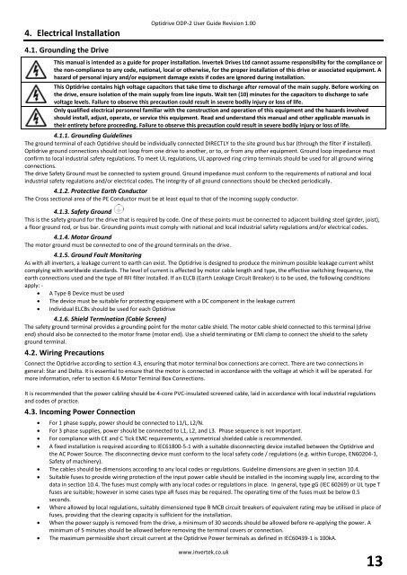
4. Electrical <strong>Installation</strong><br />
Optidrive ODP-2 User Guide Revision 1.00<br />
4.1. Grounding the <strong>Drive</strong><br />
This manual is intended as a guide for proper installation. Invertek <strong>Drive</strong>s Ltd cannot assume responsibility for the compliance or<br />
the non-compliance to any code, national, local or otherwise, for the proper installation of this drive or associated equipment. A<br />
hazard of personal injury and/or equipment damage exists if codes are ignored during installation.<br />
This Optidrive contains high voltage capacitors that take time to discharge after removal of the main supply. Before working on<br />
the drive, ensure isolation of the main supply from line inputs. Wait ten (10) minutes for the capacitors to discharge to safe<br />
voltage levels. Failure to observe this precaution could result in severe bodily injury or loss of life.<br />
Only qualified electrical personnel familiar with the construction and operation of this equipment and the hazards involved<br />
should install, adjust, operate, or service this equipment. Read and understand this manual and other applicable manuals in<br />
their entirety before proceeding. Failure to observe this precaution could result in severe bodily injury or loss of life.<br />
4.1.1. Grounding Guidelines<br />
The ground terminal of each Optidrive should be individually connected DIRECTLY to the site ground bus bar (through the filter if installed).<br />
Optidrive ground connections should not loop from one drive to another, or to, or from any other equipment. Ground loop impedance must<br />
confirm to local industrial safety regulations. To meet UL regulations, UL approved ring crimp terminals should be used for all ground wiring<br />
connections.<br />
The drive Safety Ground must be connected to system ground. Ground impedance must conform to the requirements of national and local<br />
industrial safety regulations and/or electrical codes. The integrity of all ground connections should be checked periodically.<br />
4.1.2. Protective Earth Conductor<br />
The Cross sectional area of the PE Conductor must be at least equal to that of the incoming supply conductor.<br />
4.1.3. Safety Ground<br />
This is the safety ground for the drive that is required by code. One of these points must be connected to adjacent building steel (girder, joist),<br />
a floor ground rod, or bus bar. Grounding points must comply with national and local industrial safety regulations and/or electrical codes.<br />
4.1.4. Motor Ground<br />
The motor ground must be connected to one of the ground terminals on the drive.<br />
4.1.5. Ground Fault Monitoring<br />
As with all inverters, a leakage current to earth can exist. The Optidrive is designed to produce the minimum possible leakage current whilst<br />
complying with worldwide standards. The level of current is affected by motor cable length and type, the effective switching frequency, the<br />
earth connections used and the type of RFI filter installed. If an ELCB (Earth Leakage Circuit Breaker) is to be used, the following conditions<br />
apply: -<br />
A Type B Device must be used<br />
The device must be suitable for protecting equipment with a DC component in the leakage current<br />
Individual ELCBs should be used for each Optidrive<br />
4.1.6. Shield Termination (Cable Screen)<br />
The safety ground terminal provides a grounding point for the motor cable shield. The motor cable shield connected to this terminal (drive<br />
end) should also be connected to the motor frame (motor end). Use a shield terminating or EMI clamp to connect the shield to the safety<br />
ground terminal.<br />
4.2. Wiring Precautions<br />
Connect the Optidrive according to section 4.3, ensuring that motor terminal box connections are correct. There are two connections in<br />
general: Star and Delta. It is essential to ensure that the motor is connected in accordance with the voltage at which it will be operated. For<br />
more information, refer to section 4.6 Motor Terminal Box Connections.<br />
It is recommended that the power cabling should be 4-core PVC-insulated screened cable, laid in accordance with local industrial regulations<br />
and codes of practice.<br />
4.3. Incoming Power Connection<br />
For 1 phase supply, power should be connected to L1/L, L2/N.<br />
For 3 phase supplies, power should be connected to L1, L2, and L3. Phase sequence is not important.<br />
For compliance with CE and C Tick EMC requirements, a symmetrical shielded cable is recommended.<br />
A fixed installation is required according to IEC61800-5-1 with a suitable disconnecting device installed between the Optidrive and<br />
the <strong>AC</strong> Power Source. The disconnecting device must conform to the local safety code / regulations (e.g. within Europe, EN60204-1,<br />
Safety of machinery).<br />
The cables should be dimensions according to any local codes or regulations. Guideline dimensions are given in section 10.4.<br />
Suitable fuses to provide wiring protection of the input power cable should be installed in the incoming supply line, according to the<br />
data in section 10.4. The fuses must comply with any local codes or regulations in place. In general, type gG (IEC 60269) or UL type T<br />
fuses are suitable; however in some cases type aR fuses may be required. The operating time of the fuses must be below 0.5<br />
seconds.<br />
Where allowed by local regulations, suitably dimensioned type B MCB circuit breakers of equivalent rating may be utilised in place of<br />
fuses, providing that the clearing capacity is sufficient for the installation.<br />
When the power supply is removed from the drive, a minimum of 30 seconds should be allowed before re-applying the power. A<br />
minimum of 5 minutes should be allowed before removing the terminal covers or connection.<br />
The maximum permissible short circuit current at the Optidrive Power terminals as defined in IEC60439-1 is 100kA.<br />
www.invertek.co.uk<br />
13


