AC Variable Speed Drive Installation & Operating Instructions
Optidrive P2 User Guide
Optidrive P2 User Guide
- No tags were found...

Create successful ePaper yourself
Turn your PDF publications into a flip-book with our unique Google optimized e-Paper software.
Optidrive ODP-2 User Guide Revision 1.00<br />
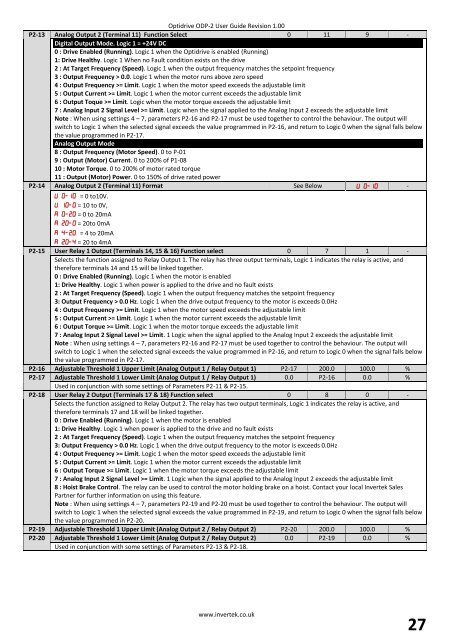
P2-13 Analog Output 2 (Terminal 11) Function Select 0 11 9 -<br />
Digital Output Mode. Logic 1 = +24V DC<br />
0 : <strong>Drive</strong> Enabled (Running). Logic 1 when the Optidrive is enabled (Running)<br />
1: <strong>Drive</strong> Healthy. Logic 1 When no Fault condition exists on the drive<br />
2 : At Target Frequency (<strong>Speed</strong>). Logic 1 when the output frequency matches the setpoint frequency<br />
3 : Output Frequency > 0.0. Logic 1 when the motor runs above zero speed<br />
4 : Output Frequency >= Limit. Logic 1 when the motor speed exceeds the adjustable limit<br />
5 : Output Current >= Limit. Logic 1 when the motor current exceeds the adjustable limit<br />
6 : Output Toque >= Limit. Logic when the motor torque exceeds the adjustable limit<br />
7 : Analog Input 2 Signal Level >= Limit. Logic when the signal applied to the Analog Input 2 exceeds the adjustable limit<br />
Note : When using settings 4 – 7, parameters P2-16 and P2-17 must be used together to control the behaviour. The output will<br />
switch to Logic 1 when the selected signal exceeds the value programmed in P2-16, and return to Logic 0 when the signal falls below<br />
the value programmed in P2-17.<br />
Analog Output Mode<br />
8 : Output Frequency (Motor <strong>Speed</strong>). 0 to P-01<br />
9 : Output (Motor) Current. 0 to 200% of P1-08<br />
10 : Motor Torque. 0 to 200% of motor rated torque<br />
11 : Output (Motor) Power. 0 to 150% of drive rated power<br />
P2-14 Analog Output 2 (Terminal 11) Format See Below -<br />
= 0 to10V.<br />
= 10 to 0V,<br />
= 0 to 20mA<br />
= 20to 0mA<br />
= 4 to 20mA<br />
= 20 to 4mA<br />
P2-15 User Relay 1 Output (Terminals 14, 15 & 16) Function select 0 7 1 -<br />
Selects the function assigned to Relay Output 1. The relay has three output terminals, Logic 1 indicates the relay is active, and<br />
therefore terminals 14 and 15 will be linked together.<br />
0 : <strong>Drive</strong> Enabled (Running). Logic 1 when the motor is enabled<br />
1: <strong>Drive</strong> Healthy. Logic 1 when power is applied to the drive and no fault exists<br />
2 : At Target Frequency (<strong>Speed</strong>). Logic 1 when the output frequency matches the setpoint frequency<br />
3: Output Frequency > 0.0 Hz. Logic 1 when the drive output frequency to the motor is exceeds 0.0Hz<br />
4 : Output Frequency >= Limit. Logic 1 when the motor speed exceeds the adjustable limit<br />
5 : Output Current >= Limit. Logic 1 when the motor current exceeds the adjustable limit<br />
6 : Output Torque >= Limit. Logic 1 when the motor torque exceeds the adjustable limit<br />
7 : Analog Input 2 Signal Level >= Limit. 1 Logic when the signal applied to the Analog Input 2 exceeds the adjustable limit<br />
Note : When using settings 4 – 7, parameters P2-16 and P2-17 must be used together to control the behaviour. The output will<br />
switch to Logic 1 when the selected signal exceeds the value programmed in P2-16, and return to Logic 0 when the signal falls below<br />
the value programmed in P2-17.<br />
P2-16 Adjustable Threshold 1 Upper Limit (Analog Output 1 / Relay Output 1) P2-17 200.0 100.0 %<br />
P2-17 Adjustable Threshold 1 Lower Limit (Analog Output 1 / Relay Output 1) 0.0 P2-16 0.0 %<br />
Used in conjunction with some settings of Parameters P2-11 & P2-15.<br />
P2-18 User Relay 2 Output (Terminals 17 & 18) Function select 0 8 0 -<br />
Selects the function assigned to Relay Output 2. The relay has two output terminals, Logic 1 indicates the relay is active, and<br />
therefore terminals 17 and 18 will be linked together.<br />
0 : <strong>Drive</strong> Enabled (Running). Logic 1 when the motor is enabled<br />
1: <strong>Drive</strong> Healthy. Logic 1 when power is applied to the drive and no fault exists<br />
2 : At Target Frequency (<strong>Speed</strong>). Logic 1 when the output frequency matches the setpoint frequency<br />
3: Output Frequency > 0.0 Hz. Logic 1 when the drive output frequency to the motor is exceeds 0.0Hz<br />
4 : Output Frequency >= Limit. Logic 1 when the motor speed exceeds the adjustable limit<br />
5 : Output Current >= Limit. Logic 1 when the motor current exceeds the adjustable limit<br />
6 : Output Torque >= Limit. Logic 1 when the motor torque exceeds the adjustable limit<br />
7 : Analog Input 2 Signal Level >= Limit. 1 Logic when the signal applied to the Analog Input 2 exceeds the adjustable limit<br />
8 : Hoist Brake Control. The relay can be used to control the motor holding brake on a hoist. Contact your local Invertek Sales<br />
Partner for further information on using this feature.<br />
Note : When using settings 4 – 7, parameters P2-19 and P2-20 must be used together to control the behaviour. The output will<br />
switch to Logic 1 when the selected signal exceeds the value programmed in P2-19, and return to Logic 0 when the signal falls below<br />
the value programmed in P2-20.<br />
P2-19 Adjustable Threshold 1 Upper Limit (Analog Output 2 / Relay Output 2) P2-20 200.0 100.0 %<br />
P2-20 Adjustable Threshold 1 Lower Limit (Analog Output 2 / Relay Output 2) 0.0 P2-19 0.0 %<br />
Used in conjunction with some settings of Parameters P2-13 & P2-18.<br />
www.invertek.co.uk<br />
27