AC Variable Speed Drive Installation & Operating Instructions
Optidrive P2 User Guide
Optidrive P2 User Guide
- No tags were found...

You also want an ePaper? Increase the reach of your titles
YUMPU automatically turns print PDFs into web optimized ePapers that Google loves.
4.7. Control Terminal Wiring<br />
<br />
<br />
<br />
<br />
Optidrive ODP-2 User Guide Revision 1.00<br />
All analog signal cables should be suitably shielded. Twisted pair cables are recommended.<br />
Power and Control Signal cables should be routed separately where possible, and must not be routed parallel to each other<br />
Signal levels of different voltages e.g. 24 Volt DC and 110 Volt <strong>AC</strong>, should not be routed in the same cable.<br />
Maximum control terminal tightening torque is 0.5Nm<br />
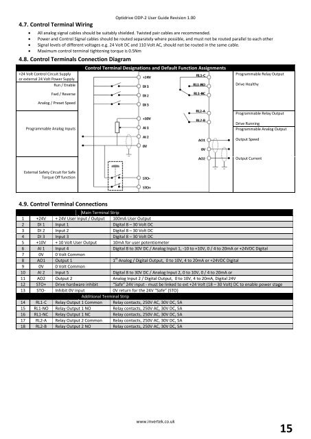
4.8. Control Terminals Connection Diagram<br />
+24 Volt Control Circuit Supply<br />
or external 24 Volt Power Supply<br />
Run / Enable<br />
Fwd / Reverse<br />
Analog / Preset <strong>Speed</strong><br />
Control Terminal Designations and Default Function Assignments<br />
Programmable Relay Output<br />
<strong>Drive</strong> Healthy<br />
Programmable Relay Output<br />
Programmable Analog Inputs<br />
<strong>Drive</strong> Running<br />
Programmable Analog Output<br />
Output <strong>Speed</strong><br />
Output Current<br />
External Safety Circuit for Safe<br />
Torque Off function<br />
4.9. Control Terminal Connections<br />
Main Terminal Strip<br />
1 +24V + 24V User Input / Output 100mA User Output<br />
2 DI 1 Input 1 Digital 8 – 30 Volt DC<br />
3 DI 2 Input 2 Digital 8 – 30 Volt DC<br />
4 DI 3 Input 3 Digital 8 – 30 Volt DC<br />
5 +10V + 10 Volt User Output 10mA for user potentiometer<br />
6 AI 1 Input 4 Digital 8 to 30V DC / Analog Input 1, -10 to +10V, 0 / 4 to 20mA or +24VDC Digital<br />
7 0V 0 Volt Common<br />
8 AO1 Output 1 1 st Analog / Digital Output, 0 to 10V, 4 to 20mA or +24VDC Digital<br />
9 0V 0 Volt Common<br />
10 AI 2 Input 5 Digital 8 to 30V DC / Analog Input 2, 0 to 10V, 0 / 4 to 20mA or<br />
11 AO2 Output 2 Analog Input 2 / Digital Output, 0 to 10V, 4 to 20mA, Digital 24V<br />
12 STO+ <strong>Drive</strong> hardware inhibit “Safe” 24V input - must be linked to ext +24 Volt (18 – 30 Volt) DC to enable power stage<br />
13 STO- Inhibit 0V input 0V return for the 24V “Safe” (STO)<br />
Additional Terminal Strip<br />
14 RL1-C Relay Output 1 Common Relay contacts, 250V <strong>AC</strong>, 30V DC, 5A<br />
15 RL1-NO Relay Output 1 NO Relay contacts, 250V <strong>AC</strong>, 30V DC, 5A<br />
16 RL1-NC Relay Output 1 NC Relay contacts, 250V <strong>AC</strong>, 30V DC, 5A<br />
17 RL2-A Relay Output 2 Common Relay contacts, 250V <strong>AC</strong>, 30V DC, 5A<br />
18 RL2-B Relay Output 2 NO Relay contacts, 250V <strong>AC</strong>, 30V DC, 5A<br />
www.invertek.co.uk<br />
15