AC Variable Speed Drive Installation & Operating Instructions
Optidrive P2 User Guide
Optidrive P2 User Guide
- No tags were found...

Create successful ePaper yourself
Turn your PDF publications into a flip-book with our unique Google optimized e-Paper software.
Optidrive ODP-2 User Guide Revision 1.00<br />
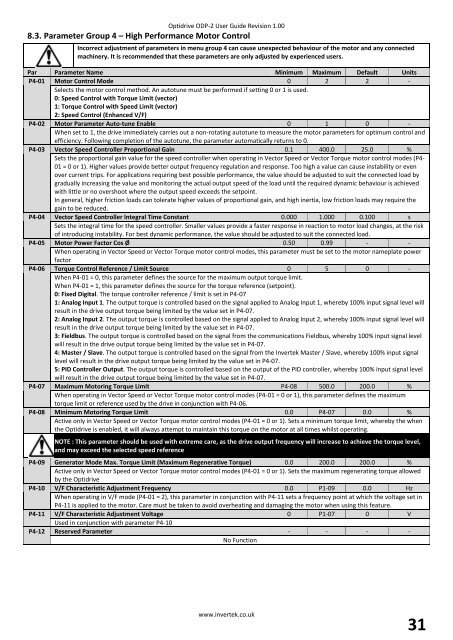
8.3. Parameter Group 4 – High Performance Motor Control<br />
Incorrect adjustment of parameters in menu group 4 can cause unexpected behaviour of the motor and any connected<br />
machinery. It is recommended that these parameters are only adjusted by experienced users.<br />
Par Parameter Name Minimum Maximum Default Units<br />
P4-01 Motor Control Mode 0 2 2 -<br />
Selects the motor control method. An autotune must be performed if setting 0 or 1 is used.<br />
0: <strong>Speed</strong> Control with Torque Limit (vector)<br />
1: Torque Control with <strong>Speed</strong> Limit (vector)<br />
2: <strong>Speed</strong> Control (Enhanced V/F)<br />
P4-02 Motor Parameter Auto-tune Enable 0 1 0 -<br />
When set to 1, the drive immediately carries out a non-rotating autotune to measure the motor parameters for optimum control and<br />
efficiency. Following completion of the autotune, the parameter automatically returns to 0.<br />
P4-03 Vector <strong>Speed</strong> Controller Proportional Gain 0.1 400.0 25.0 %<br />
Sets the proportional gain value for the speed controller when operating in Vector <strong>Speed</strong> or Vector Torque motor control modes (P4-<br />
01 = 0 or 1). Higher values provide better output frequency regulation and response. Too high a value can cause instability or even<br />
over current trips. For applications requiring best possible performance, the value should be adjusted to suit the connected load by<br />
gradually increasing the value and monitoring the actual output speed of the load until the required dynamic behaviour is achieved<br />
with little or no overshoot where the output speed exceeds the setpoint.<br />
In general, higher friction loads can tolerate higher values of proportional gain, and high inertia, low friction loads may require the<br />
gain to be reduced.<br />
P4-04 Vector <strong>Speed</strong> Controller Integral Time Constant 0.000 1.000 0.100 s<br />
Sets the integral time for the speed controller. Smaller values provide a faster response in reaction to motor load changes, at the risk<br />
of introducing instability. For best dynamic performance, the value should be adjusted to suit the connected load.<br />
P4-05 Motor Power Factor Cos Ø 0.50 0.99 - -<br />
When operating in Vector <strong>Speed</strong> or Vector Torque motor control modes, this parameter must be set to the motor nameplate power<br />
factor<br />
P4-06 Torque Control Reference / Limit Source 0 5 0 -<br />
When P4-01 = 0, this parameter defines the source for the maximum output torque limit.<br />
When P4-01 = 1, this parameter defines the source for the torque reference (setpoint).<br />
0: Fixed Digital. The torque controller reference / limit is set in P4-07<br />
1: Analog Input 1. The output torque is controlled based on the signal applied to Analog Input 1, whereby 100% input signal level will<br />
result in the drive output torque being limited by the value set in P4-07.<br />
2: Analog Input 2. The output torque is controlled based on the signal applied to Analog Input 2, whereby 100% input signal level will<br />
result in the drive output torque being limited by the value set in P4-07.<br />
3: Fieldbus. The output torque is controlled based on the signal from the communications Fieldbus, whereby 100% input signal level<br />
will result in the drive output torque being limited by the value set in P4-07.<br />
4: Master / Slave. The output torque is controlled based on the signal from the Invertek Master / Slave, whereby 100% input signal<br />
level will result in the drive output torque being limited by the value set in P4-07.<br />
5: PID Controller Output. The output torque is controlled based on the output of the PID controller, whereby 100% input signal level<br />
will result in the drive output torque being limited by the value set in P4-07.<br />
P4-07 Maximum Motoring Torque Limit P4-08 500.0 200.0 %<br />
When operating in Vector <strong>Speed</strong> or Vector Torque motor control modes (P4-01 = 0 or 1), this parameter defines the maximum<br />
torque limit or reference used by the drive in conjunction with P4-06.<br />
P4-08 Minimum Motoring Torque Limit 0.0 P4-07 0.0 %<br />
Active only in Vector <strong>Speed</strong> or Vector Torque motor control modes (P4-01 = 0 or 1). Sets a minimum torque limit, whereby the when<br />
the Optidrive is enabled, it will always attempt to maintain this torque on the motor at all times whilst operating.<br />
NOTE : This parameter should be used with extreme care, as the drive output frequency will increase to achieve the torque level,<br />
and may exceed the selected speed reference<br />
P4-09 Generator Mode Max. Torque Limit (Maximum Regenerative Torque) 0.0 200.0 200.0 %<br />
Active only in Vector <strong>Speed</strong> or Vector Torque motor control modes (P4-01 = 0 or 1). Sets the maximum regenerating torque allowed<br />
by the Optidrive<br />
P4-10 V/F Characteristic Adjustment Frequency 0.0 P1-09 0.0 Hz<br />
When operating in V/F mode (P4-01 = 2), this parameter in conjunction with P4-11 sets a frequency point at which the voltage set in<br />
P4-11 is applied to the motor. Care must be taken to avoid overheating and damaging the motor when using this feature.<br />
P4-11 V/F Characteristic Adjustment Voltage 0 P1-07 0 V<br />
Used in conjunction with parameter P4-10<br />
P4-12 Reserved Parameter - - - -<br />
No Function<br />
www.invertek.co.uk<br />
31