AC Variable Speed Drive Installation & Operating Instructions
Optidrive P2 User Guide
Optidrive P2 User Guide
- No tags were found...

Create successful ePaper yourself
Turn your PDF publications into a flip-book with our unique Google optimized e-Paper software.
3.5. Guidelines for Enclosure mounting (IP20 Units)<br />
<br />
<br />
<br />
<br />
<br />
Optidrive ODP-2 User Guide Revision 1.00<br />
<strong>Installation</strong> should be in a suitable enclosure, according to EN60529 or other relevant local codes or standards.<br />
Enclosures should be made from a thermally conductive material.<br />
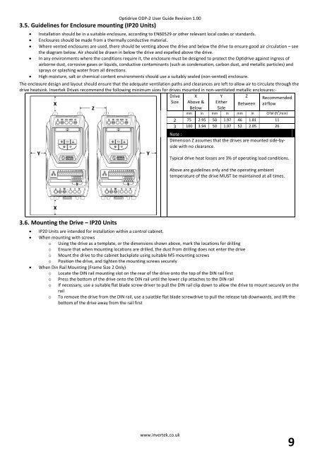
Where vented enclosures are used, there should be venting above the drive and below the drive to ensure good air circulation – see<br />
the diagram below. Air should be drawn in below the drive and expelled above the drive.<br />
In any environments where the conditions require it, the enclosure must be designed to protect the Optidrive against ingress of<br />
airborne dust, corrosive gases or liquids, conductive contaminants (such as condensation, carbon dust, and metallic particles) and<br />
sprays or splashing water from all directions.<br />
High moisture, salt or chemical content environments should use a suitably sealed (non-vented) enclosure.<br />
The enclosure design and layout should ensure that the adequate ventilation paths and clearances are left to allow air to circulate through the<br />
drive heatsink. Invertek <strong>Drive</strong>s recommend the following minimum sizes for drives mounted in non-ventilated metallic enclosures:-<br />
<strong>Drive</strong> X<br />
Y<br />
Z Recommended<br />
Size Above & Either Between airflow<br />
Below Side<br />
mm in mm in mm in CFM (ft 3 /min)<br />
2 75 2.95 50 1.97 46 1.81 11<br />
3 100 3.94 50 1.97 52 2.05 26<br />
Note :<br />
Dimension Z assumes that the drives are mounted side-byside<br />
with no clearance.<br />
Typical drive heat losses are 3% of operating load conditions.<br />
Above are guidelines only and the operating ambient<br />
temperature of the drive MUST be maintained at all times.<br />
3.6. Mounting the <strong>Drive</strong> – IP20 Units<br />
<br />
<br />
<br />
IP20 Units are intended for installation within a control cabinet.<br />
When mounting with screws<br />
o Using the drive as a template, or the dimensions shown above, mark the locations for drilling<br />
o Ensure that when mounting locations are drilled, the dust from drilling does not enter the drive<br />
o Mount the drive to the cabinet backplate using suitable M5 mounting screws<br />
o Position the drive, and tighten the mounting screws securely<br />
When Din Rail Mounting (Frame Size 2 Only)<br />
o Locate the DIN rail mounting slot on the rear of the drive onto the top of the DIN rail first<br />
o Press the bottom of the drive onto the DIN rail until the lower clip attaches to the DIN rail<br />
o If necessary, use a suitable flat blade screw driver to pull the DIN rail clip down to allow the drive to mount securely on the<br />
rail<br />
o To remove the drive from the DIN rail, use a suiatble flat blade screwdrive to pull the release tab downwards, and lift the<br />
bottom of the drive away from the rail first<br />
www.invertek.co.uk<br />
9