AC Variable Speed Drive Installation & Operating Instructions
Optidrive P2 User Guide
Optidrive P2 User Guide
- No tags were found...

You also want an ePaper? Increase the reach of your titles
YUMPU automatically turns print PDFs into web optimized ePapers that Google loves.
Optidrive ODP-2 User Guide Revision 1.01<br />
An optional Input Choke is recommended to be installed in the supply line for drives where any of the following conditions occur:-<br />
o The incoming supply impedance is low or the fault level / short circuit current is high<br />
o The supply is prone to dips or brown outs<br />
o An imbalance exists on the supply (3 phase drives)<br />
o The power supply to the drive is via a busbar and brush gear system (typically overhead Cranes).<br />
In all other installations, an input choke is recommended to ensure protection of the drive against power supply faults. Part numbers<br />
are shown in the table.<br />
Supply Frame Size <strong>AC</strong> Input Inductor<br />
230 Volt<br />
2 OD-IL221-IN<br />
1 Phase<br />
3 OD-IL321-IN<br />
400 Volt<br />
2 OD-IL-243-IN<br />
3 Phase<br />
3 OD-IL-343-IN<br />
4.4. Operation of 3 Phase drives from a Single Phase Supply<br />
A special function of Optidrive P2 allows all drives designed for operation on 3 phase supplies to be operated on a single phase supply of the<br />
correct rated voltage at up to 50% of the nominal capacity.<br />
For Example, Model Number ODP-2-64450-3KA4N can be operated on a single phase supply, 380 – 480 volts, with the maximum output<br />
current limited to 45 Amps<br />
The supply should be connected to the L1 and L2 terminals of the drive.<br />
4.5. <strong>Drive</strong> and Motor Connection<br />
<br />
<br />
<br />
<br />
<br />
<br />
The motor should be connected to the Optidrive U, V, and W terminals using a suitable 3 or 4 core cable. Where a 3 core cable is<br />
utilised, with the shield operating as an earth conductor, the shield must have a cross sectional area at least equal to the phase<br />
conductors when they are made from the same material. Where a 4 core cable is utilised, the earth conductor must be of at least<br />
equal cross sectional area and manufactured from the same material as the phase conductors.<br />
The motor earth must be connected to one of the Optidrive earth terminals.<br />
For compliance with the European EMC directive, a suitable screened (shielded) cable should be used. Braided or twisted type<br />
screened cable where the screen covers at least 85% of the cable surface area, designed with low impedance to HF signals are<br />
recommended as a minimum. <strong>Installation</strong> within a suitable steel or copper tube is generally also acceptable.<br />
The cable screen should be terminated at the motor end using an EMC type gland allowing connection to the motor body through<br />
the largest possible surface area<br />
Where drives are mounted in a steel control panel enclosure, the cable screen may be terminated directly to the control panel using<br />
a suitable EMC clamp or gland, as close to the drive as possible.<br />
For IP55 drives, connect the motor cable screen to the internal ground clamp<br />
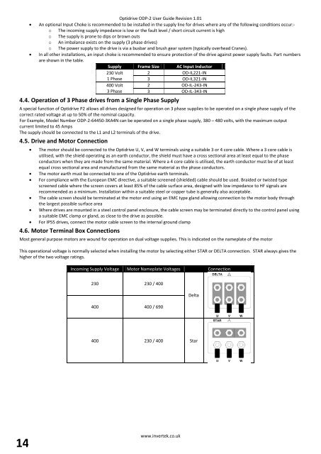
4.6. Motor Terminal Box Connections<br />
Most general purpose motors are wound for operation on dual voltage supplies. This is indicated on the nameplate of the motor<br />
This operational voltage is normally selected when installing the motor by selecting either STAR or DELTA connection. STAR always gives the<br />
higher of the two voltage ratings.<br />
Incoming Supply Voltage Motor Nameplate Voltages Connection<br />
230 230 / 400<br />
400 400 / 690<br />
Delta<br />
400 230 / 400 Star<br />
14<br />
www.invertek.co.uk