CATALOGUE
ZHP08C/GB -72 dpi - versione 20080916 - Zucchini
ZHP08C/GB -72 dpi - versione 20080916 - Zucchini

Create successful ePaper yourself
Turn your PDF publications into a flip-book with our unique Google optimized e-Paper software.
130<br />
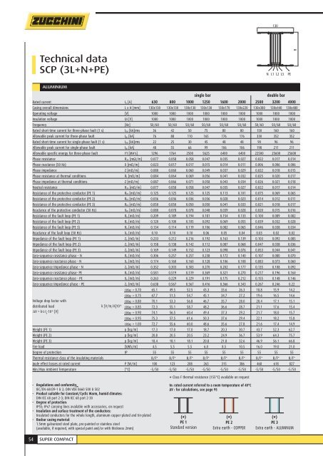
Technical data<br />
SCP (3L+N+PE)<br />
N L1 L2 L3 PE<br />
Caduta distributed tensione load con carico distribuito k [V/m/A]10 -6 cosϕ = 0.85 72.3 55.1 58.7 48.2 36.6 28.7 21.1 17.6 15.4<br />
ALUMINIUM<br />
single bar<br />
double bar<br />
Rated current I n [A] 630 800 1000 1250 1600 2000 2500 3200 4000<br />
Casing overall dimensions L x H [mm] 130x130 130x130 130x130 130x130 130x170 130x220 130x380 130x440 130x480<br />
Operating voltage [V] 1000 1000 1000 1000 1000 1000 1000 1000 1000<br />
Insulation voltage Ui [V] 1000 1000 1000 1000 1000 1000 1000 1000 1000<br />
Frequency [Hz] 50/60 50/60 50/60 50/60 50/60 50/60 50/60 50/60 50/60<br />
Rated short-time current for three-phase fault (1 s) I CW [kA]rms 36 42 50 75 80 80 150 160 160<br />
Allowable peak current for three-phase fault I pk [kA] 76 88 110 165 176 176 330 352 352<br />
Rated short-time current for single-phase fault (1 s) I CW [kA]rms 22 25 30 45 48 48 90 96 96<br />
Allowable peak current for single-phase fault I pk [kA] 48 55 66 99 106 106 198 211 211<br />
Allowable specific energy for three-phase fault I 2 t [MA 2 s] 1296 1764 2500 5625 6400 6400 22500 25600 25600<br />
Phase resistance R 20 [mΩ/m] 0.077 0.058 0.058 0.047 0.035 0.027 0.022 0.017 0.014<br />
Phase reactance (50 Hz) X [mΩ/m] 0.023 0.017 0.017 0.015 0.014 0.011 0.006 0.006 0.006<br />
Phase impedance Z [mΩ/m] 0.080 0.060 0.060 0.049 0.037 0.029 0.022 0.018 0.015<br />
Phase resistance at thermal conditions R t [mΩ/m] 0.084 0.064 0.069 0.056 0.041 0.032 0.025 0.020 0.017<br />
Phase impedance at thermal conditions Z [mΩ/m] 0.087 0.066 0.071 0.058 0.043 0.034 0.026 0.021 0.018<br />
Neutral resistance R 20 [mΩ/m] 0.077 0.058 0.058 0.047 0.035 0.027 0.022 0.017 0.014<br />
Resistance of the protective conductor (PE 1) R PE [mΩ/m] 0.125 0.125 0.125 0.125 0.113 0.101 0.075 0.069 0.065<br />
Resistance of the protective conductor (PE 2) R PE [mΩ/m] 0.036 0.036 0.036 0.036 0.028 0.023 0.014 0.012 0.011<br />
Resistance of the protective conductor (PE 3) R PE [mΩ/m] 0.050 0.050 0.050 0.050 0.041 0.033 0.021 0.018 0.017<br />
Reactance of the protective conductor (50 Hz) X PE [mΩ/m] 0.080 0.078 0.078 0.048 0.039 0.028 0.020 0.015 0.016<br />
Resistance of the fault loop (PE 1) R o [mΩ/m] 0.209 0.189 0.194 0.181 0.154 0.133 0.100 0.089 0.082<br />
Resistance of the fault loop (PE 2) R o [mΩ/m] 0.120 0.100 0.105 0.092 0.069 0.055 0.039 0.032 0.028<br />
Resistance of the fault loop (PE 3) R o [mΩ/m] 0.134 0.114 0.119 0.106 0.082 0.065 0.046 0.038 0.034<br />
Reactance of the fault loop (50 Hz) X o [mΩ/m] 0.10 0.10 0.10 0.06 0.05 0.04 0.03 0.02 0.02<br />
Impedance of the fault loop (PE 1) Z o [mΩ/m] 0.233 0.212 0.216 0.192 0.163 0.139 0.103 0.092 0.085<br />
Impedance of the fault loop (PE 2) Z o [mΩ/m] 0.158 0.138 0.142 0.112 0.087 0.068 0.047 0.038 0.036<br />
Impedance of the fault loop (PE 3) Z o [mΩ/m] 0.169 0.149 0.152 0.123 0.098 0.076 0.053 0.044 0.041<br />
Zero-sequence resistance phase - N R o [mΩ/m] 0.306 0.257 0.257 0.238 0.172 0.140 0.107 0.080 0.070<br />
Zero-sequence reactance phase - N X o [mΩ/m] 0.174 0.160 0.160 0.128 0.106 0.108 0.083 0.073 0.060<br />
Zero-sequence Impedance phase - N Z o [mΩ/m] 0.352 0.303 0.303 0.270 0.202 0.177 0.135 0.108 0.092<br />
Zero-sequence resistance phase- PE R o [mΩ/m] 0.581 0.519 0.519 0.369 0.321 0.270 0.217 0.196 0.164<br />
Zero-sequence reactance phase - PE X o [mΩ/m] 0.263 0.229 0.229 0.191 0.175 0.212 0.155 0.148 0.146<br />
Zero-sequence Impedance phase - PE Z o [mΩ/m] 0.638 0.567 0.567 0.416 0.366 0.343 0.267 0.246 0.22<br />
cosϕ = 0.70 65.1 49.5 52.5 43.3 33.6 26.3 18.8 15.9 14.2<br />
cosϕ = 0.75 67.7 51.5 54.7 45.1 34.7 27.2 19.6 16.5 14.6<br />
Voltage drop factor with<br />
cosϕ = 0.80 70.1 53.3 56.8 46.7 35.7 28.0 20.4 17.1 15.1<br />
ΔV = k . L . I .<br />
e<br />
10<br />
-6<br />
[V]<br />
cosϕ = 0.90 74.1 56.5 60.4 49.4 37.3 29.2 21.7 18.0 15.7<br />
cosϕ = 0.95 75.3 57.5 61.6 50.3 37.6 29.4 22.1 18.2 15.8<br />
cosϕ = 1.00 72.7 55.6 60.0 48.6 35.6 27.8 21.6 17.4 14.9<br />
Weight (PE 1) p [kg/m] 17.3 17.0 17.0 18.7 20.3 30.7 43.7 52.3 62.7<br />
Weight (PE 2) p [kg/m] 20.8 20.5 20.5 23.2 24.9 36.7 53.9 64.3 75.7<br />
Weight (PE 3) p [kg/m] 18.4 18.1 18.1 20.8 21.8 32.6 46.9 56.1 66.8<br />
Fire load [kWh/m] 4.5 5.5 5.5 6.0 8.5 10.5 16.0 19.0 21.0<br />
Degree of protection IP 55 55 55 55 55 55 55 55 55<br />
Thermal resistance class of the insulating materials B/F * B/F * B/F * B/F * B/F * B/F * B/F * B/F * B/F *<br />
Joule effect losses at rated current P [W/m] 100 123 208 263 315 386 468 618 827<br />
Min/Max Ambient Temperature [°C] -5/50 -5/50 -5/50 -5/50 -5/50 -5/50 -5/50 -5/50 -5/50<br />
* Class F thermal resistance (155°C) available on request<br />
H<br />
- Regulations and conformity:<br />
IEC/EN 60439-1 2; DIN VDE 0660 500 502<br />
- Product suitable for Constant/Cyclic Warm, humid climates:<br />
DIN IEC 68 part 2-3; DIN IEC 68 part 2-30<br />
- Degree of protection:<br />
IP55; IPx7 carrying lines available with accessories, on request<br />
- Insulation and surface treatment of the conductors:<br />
Insulated conductors for the whole length, aluminum copper-plated and tin-plated<br />
- Busbar casing material:<br />
1.5mm galvanized steel plate, pre-painted or stainless steel<br />
(available, if required, with special paint and/or with thickness 2mm)<br />
In: rated current referred to a room temperature of 40°C<br />
ΔV : for calculations, see page 95<br />
(*)<br />
PE 1<br />
Standard version<br />
(*)<br />
PE 2<br />
Extra earth - COPPER<br />
(*)<br />
PE 3<br />
Extra earth - ALUMINUM<br />
54 SUPER COMPACT