CATALOGUE
ZHP08C/GB -72 dpi - versione 20080916 - Zucchini
ZHP08C/GB -72 dpi - versione 20080916 - Zucchini

You also want an ePaper? Increase the reach of your titles
YUMPU automatically turns print PDFs into web optimized ePapers that Google loves.
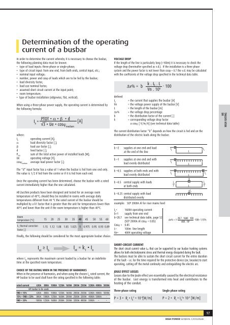
Determination of the operating<br />
current of a busbar<br />
In order to determine the current whereby it is necessary to choose the busbar,<br />
the following planning data must be known:<br />
• type of load inputs: three-phase or single-phase;<br />
• type of circuit input: from one end, from both ends, central input, etc.;<br />
• nominal input voltage;<br />
• number, power and cosφ of loads which are to be fed by the busbar;<br />
• load diversity factor;<br />
• load use nominal factor;<br />
• assumed short circuit current at the input point;<br />
• room temperature;<br />
• type of busbar installation (edgewise, flat, vertical).<br />
VOLTAGE DROP<br />
Δv% = b<br />
defined<br />
I b<br />
Vn<br />
L<br />
Δv%<br />
PTOT • α • β • d<br />
k<br />
I b<br />
=<br />
[A]<br />
√3 • Ue • cosϕ medium<br />
b =2<br />
b =1<br />
I b<br />
=<br />
15 20 25 30 35 40 45 50 55 60<br />
1.15 1.12 1.08 1.05 1.025 1 0.975 0.95 0.93 0.89<br />
I nt<br />
≥ I b<br />
I nt<br />
= k 1<br />
• I n<br />
When using a three-phase power supply, the operating current is determined by<br />
the following formula:<br />
where:<br />
I b<br />
operating current [A];<br />
α load diversity factor [.];<br />
β load use factor [.];<br />
d feed factor [.];<br />
P TOT<br />
sum of the total active power of installed loads [W];<br />
Ue operating voltage [V];<br />
cosϕ medium<br />
average load power factor [.];<br />
The “d” input factor has a value of 1 when the busbar is fed from one end only.<br />
The value is 1/2 if fed from the centre or if it is fed from each end.<br />
Once the operating current has been determined, choose the busbar with a rated<br />
current immediately higher than the one calculated.<br />
All Zucchini products have been designed and tested for an average room<br />
temperature of 40°C; should they be installed in rooms with average daily<br />
temperatures different from 40 °C the rated current of the busbar should be<br />
multiplied by a k1 factor that is greater than the unit for temperatures lower than<br />
40°C and lower than the unit if the room temperature is higher than 40°C.<br />
Room<br />
temperature [°C]<br />
k 1<br />
thermal correction<br />
factor [.]<br />
Finally, the following should be considered for the most appropriate busbar choice:<br />
where I nt<br />
represents the maximum current loaded by a busbar for an indefinite<br />
time at the specified room temperature.<br />
CHOICE OF THE RATING WHEN IN THE PRESENCE OF HARMONICS<br />
When in the presence of harmonics, and when using the chosen I nt<br />
rated current, the<br />
HP busbar to be used shall have the rating specified in the following table:<br />
rated current 630A 800A 1000A 1250A 1600A 2000A 2500A 3200A 4000A 5000A<br />
HP busbar to be used:<br />
THD ≤ 15% 630A 800A 1000A 1250A 1600A 2000A 2500A 3200A 4000A 5000A<br />
15% < THD ≤ 33% 800A 1000A 1250A 1600A 2000A 2500A 3200A 4000A 5000A -<br />
THD > 33% 1000A 1250A 1600A 2000A 2500A 3200A 4000A 5000A - -<br />
If the length of the line is particularly long (>100m) it is necessary to check the<br />
voltage drop (hereinafter specified as v.d.). If the installation is a three phase<br />
system and the power factor is not lower than cosφ = 0.7 the v.d. may be calculated<br />
with the coefficients of the voltage drop specified in the technical data table.<br />
k . I b . L<br />
Vn . 10 6 . 100<br />
= the current that supplies the busbar [A]<br />
= the voltage power supply of the busbar [V]<br />
= the length of the busbar [m]<br />
= the voltage drop percentage<br />
b = the distribution factor of the current [.]<br />
= corresponding voltage drop factor<br />
a cosϕ [ V/m/A] (see technical data table)<br />
The current distribution factor “b” depends on how the circuit is fed and on the<br />
distribution of the electric loads along the busbar:<br />
supplies at one end and load<br />
at the end of the line<br />
supplies at one end and with<br />
load evenly distributed<br />
b =0.5 supplies at both ends and with<br />
load evenly distributed<br />
b =0.5 central supply with loads<br />
at both ends<br />
b =0.25 central supply with load<br />
distributed evenly<br />
example: SCP 2000A Al for riser mains feed<br />
1600A operating current<br />
b=1 supply from one end<br />
k=28.7 see technical data table, page 52<br />
(SCP 2000A Al cosϕ = 0.85)<br />
Cosϕ = 0.85<br />
L= 100m line length<br />
Vn= 400V operating voltage<br />
I b<br />
L<br />
I b<br />
I b<br />
L<br />
I b<br />
L<br />
I b<br />
I b<br />
2 L<br />
I b<br />
I b<br />
2<br />
Δv% = 1 . 28.7 . 1600 . 100<br />
400 . 10 6 . 100= 1.15%<br />
SHORT-CIRCUIT CURRENT<br />
The short circuit current value I CW that can be supported by our busbar trunking systems<br />
allows for both electrodynamic stress and thermal energy dissipated during the fault.<br />
The busbars must be able to sustain the short circuit current for the entire duration<br />
of the fault - i.e. for the time required for the protective device (circ. breacker) to start<br />
operating, cutting off the metal continuity and extinguishing the electric arc.<br />
JOULE EFFECT LOSSES<br />
Losses due to the Joule effect are essentially caused by the electrical resistance<br />
of the busbar. Lost energy is transformed into heat and contributes to the<br />
heating of the conduit.<br />
Three-phase rating<br />
Single phase rating<br />
P = 3 • R t<br />
• I b<br />
2<br />
• 10 -3 [W/m] P = 2 • R t<br />
• I b2<br />
• 10 -3 [W/m]<br />
MAS400 HR<br />
HIGH RATING<br />
97<br />
HIGH POWER GENERAL <strong>CATALOGUE</strong>