Principles and Practical Aspects of Preparative Liquid Chromatography

You also want an ePaper? Increase the reach of your titles
YUMPU automatically turns print PDFs into web optimized ePapers that Google loves.
Pump<br />
Sampling loop<br />
Metering device<br />
Waste<br />
Needle seat<br />
4<br />
5<br />
6<br />
1<br />
3<br />
2<br />
Autosampler<br />
Column<br />
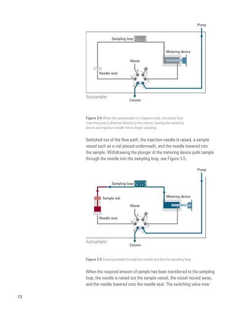
Figure 3.4 When the autosampler is in bypass mode, the eluent flow<br />
from the pump is diverted directly to the column, leaving the metering<br />
device <strong>and</strong> injection needle free to begin sampling.<br />
Switched out <strong>of</strong> the flow path, the injection needle is raised, a sample<br />
vessel such as a vial placed underneath, <strong>and</strong> the needle lowered into<br />
the sample. Withdrawing the plunger <strong>of</strong> the metering device pulls sample<br />
through the needle into the sampling loop, see Figure 3.5.<br />
Pump<br />
Sampling loop<br />
Sample vial<br />
Metering device<br />
Waste<br />
Needle seat<br />
4<br />
5<br />
6<br />
1<br />
3<br />
2<br />
Autosampler<br />
Column<br />
Figure 3.5 Drawing sample through the needle <strong>and</strong> into the sampling loop.<br />
When the required amount <strong>of</strong> sample has been transferred to the sampling<br />
loop, the needle is raised out the sample vessel, the vessel moved away,<br />
<strong>and</strong> the needle lowered onto the needle seat. The switching valve now<br />
13