Principles and Practical Aspects of Preparative Liquid Chromatography

You also want an ePaper? Increase the reach of your titles
YUMPU automatically turns print PDFs into web optimized ePapers that Google loves.
[Norm.]<br />
7.584<br />
3000<br />
2000<br />
2.791<br />
5.720<br />
1000<br />
0<br />
1 2<br />
3 4 5 6 7 8<br />
Time [min]<br />
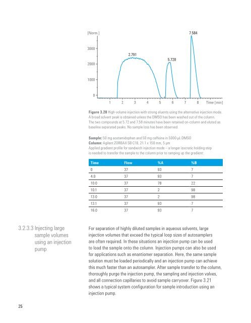
Figure 3.20 High-volume injection with strong eluents using the alternative injection mode.<br />
A broad solvent peak is obtained unless the DMSO has been washed out <strong>of</strong> the column.<br />
The two compounds at 5.72 <strong>and</strong> 7.58 minutes have been retained on-column <strong>and</strong> eluted as<br />
baseline separated peaks. No sample loss has been observed.<br />
Sample: 50 mg acetamidophen <strong>and</strong> 50 mg caffeine in 5000 µL DMSO<br />
Column: Agilent ZORBAX SB C18, 21.1 x 150 mm, 5 µm<br />
Applied gradient pr<strong>of</strong>ile for s<strong>and</strong>wich injection mode – a longer isocratic holding step<br />
is needed to transfer the sample to the column prior to ramping up the gradient:<br />
Time Flow %A %B<br />
0 37 93 7<br />
4.0 37 93 7<br />
10.0 37 78 22<br />
10.1 37 2 98<br />
13.0 37 2 98<br />
13.1 37 93 7<br />
16.0 37 93 7<br />
3.2.3.3 Injecting large<br />
sample volumes<br />
using an injection<br />
pump<br />
For separation <strong>of</strong> highly diluted samples in aqueous solvents, large<br />
injection volumes that exceed the typical loop sizes <strong>of</strong> autosamplers<br />
are <strong>of</strong>ten required. In these situations an injection pump can be used<br />
to load the sample onto the column. Injection pumps can also be used<br />
for applications such as enantiomer separation. Here, the same sample<br />
solution must be loaded periodically <strong>and</strong> an injection pump can achieve<br />
this much faster than an autosampler. After sample transfer to the column,<br />
thoroughly purge the injection pump, the sampling <strong>and</strong> injection valves,<br />
<strong>and</strong> all connection capillaries to avoid sample carryover. Figure 3.21<br />
shows a typical system configuration for sample introduction using an<br />
injection pump.<br />
25