Principles and Practical Aspects of Preparative Liquid Chromatography

Create successful ePaper yourself
Turn your PDF publications into a flip-book with our unique Google optimized e-Paper software.
3.2.2 Fixed-loop design<br />
<strong>of</strong> autosampler<br />
When working with a system where – in alternating mode –<br />
analytical‐scale <strong>and</strong> preparative scale injection volumes are required, the<br />
size <strong>of</strong> the sample loop <strong>of</strong> a flow-through-needle design <strong>of</strong> autosampler<br />
will contribute significantly to the dwell volume. Systems with large dwell<br />
volumes will not perform well when using analytical flow rates. For these<br />
applications the fixed-loop design <strong>of</strong> autosampler with two sample loops<br />
<strong>of</strong> different sizes can eliminate this dilemma. A switching valve is used<br />
to create completely separate analytical <strong>and</strong> preparative flow paths.<br />
Nevertheless, there are several aspects we need to consider to be able<br />
to work successfully with this fixed-loop design <strong>of</strong> autosampler with<br />
dual loops.<br />
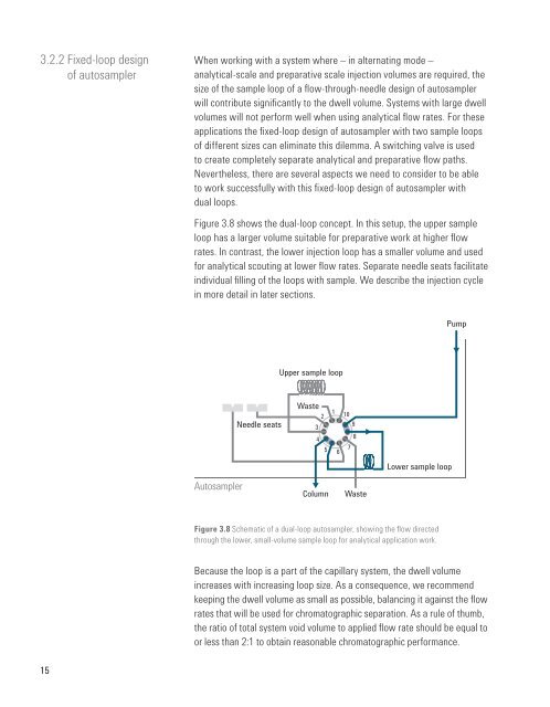
Figure 3.8 shows the dual-loop concept. In this setup, the upper sample<br />
loop has a larger volume suitable for preparative work at higher flow<br />
rates. In contrast, the lower injection loop has a smaller volume <strong>and</strong> used<br />
for analytical scouting at lower flow rates. Separate needle seats facilitate<br />
individual filling <strong>of</strong> the loops with sample. We describe the injection cycle<br />
in more detail in later sections.<br />
Pump<br />
Upper sample loop<br />
Autosampler<br />
Needle seats<br />
Waste<br />
2<br />
3<br />
4<br />
5<br />
Column<br />
1 10<br />
9<br />
6<br />
7<br />
8<br />
Waste<br />
Lower sample loop<br />
Figure 3.8 Schematic <strong>of</strong> a dual-loop autosampler, showing the flow directed<br />
through the lower, small-volume sample loop for analytical application work.<br />
Because the loop is a part <strong>of</strong> the capillary system, the dwell volume<br />
increases with increasing loop size. As a consequence, we recommend<br />
keeping the dwell volume as small as possible, balancing it against the flow<br />
rates that will be used for chromatographic separation. As a rule <strong>of</strong> thumb,<br />
the ratio <strong>of</strong> total system void volume to applied flow rate should be equal to<br />
or less than 2:1 to obtain reasonable chromatographic performance.<br />
15