Principles and Practical Aspects of Preparative Liquid Chromatography

You also want an ePaper? Increase the reach of your titles
YUMPU automatically turns print PDFs into web optimized ePapers that Google loves.
Detector<br />
Diverter<br />
valve<br />
Fraction containers<br />
Fraction collector<br />
Waste<br />
Figure 3.36 Schematics <strong>of</strong> a fraction collector, showing the basic functional parts.<br />
3.5.5.1 Fraction delay<br />
sensor<br />
To determine the exact delay time <strong>of</strong> a peak between the detector flow cell<br />
<strong>and</strong> the diverter valve, Agilent fraction collectors can be equipped with<br />
a fraction delay sensor. During a calibration process this device measures<br />
the time required for the peak to travel from the detector to the delay<br />
sensor, which is located adjacent to the diverter valve. The measured time<br />
difference is transformed into a delay volume using the applied flow rate<br />
feedback from the solvent delivery system. The value <strong>of</strong> the delay volume<br />
is saved in the firmware <strong>of</strong> the fraction collector for future calculations<br />
<strong>of</strong> delay time when different flow rates are used. Delay time calibration<br />
is not repeated as long as the tubing remains the same.<br />
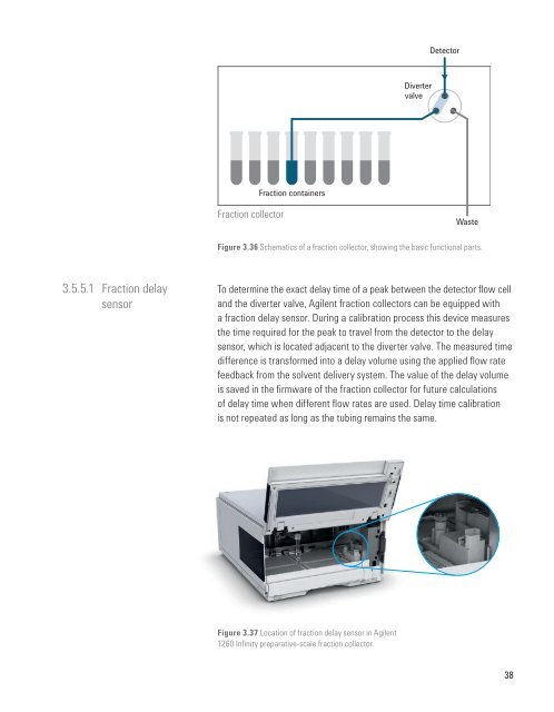
Figure 3.37 Location <strong>of</strong> fraction delay sensor in Agilent<br />
1260 Infinity preparative-scale fraction collector.<br />
38