SIM0216

You also want an ePaper? Increase the reach of your titles
YUMPU automatically turns print PDFs into web optimized ePapers that Google loves.
LIGHT MICROSCOPY<br />
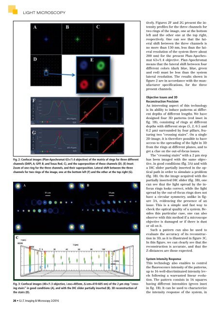
tively. Figures 2F and 2G present the intensity<br />
profiles for the three channels for<br />
two rings of the image, one at the bottom<br />
left and the other one at the top right,<br />
respectively. One can see that the lateral<br />
shift between the three channels is<br />
no more than 130 nm, less than the lateral<br />
resolution of the system (here about<br />
200 nm) for the present Plan-Apochromat<br />
63×/1.4 objective. Plan-Apochromat<br />
means that the lateral shift between four<br />
different colors (dark blue, blue, green<br />
and red) must be less than the system<br />
lateral resolution. The results shown in<br />
figure 2 are in accordance with the manufacturer<br />
specifications, for the three<br />
present channels.<br />
Fig. 2: Confocal images (Plan-Apochromat 63×/1.4 objective) of the matrix of rings for three different<br />
channels (DAPI, A; GFP, B; and Texas Red, C), and the superposition of these channels (D). (E) Inset:<br />
Zoom of one ring for the three channels, and their superposition. Lateral shift between the three<br />
channels for two rings of the image, one at the bottom left (F) and the other at the top right (G).<br />
Fig. 3: Confocal images (40×/1.3 objective, λexc=405nm, Δλem=410-605 nm) of the 2 µm step “crossing<br />
stairs” in good conditions (A), and with the DIC slider partially inserted (B). 3D reconstruction of<br />
the stairs (D).<br />
Objective Issues and 3D<br />
Reconstruction Precision<br />
An interesting aspect of this technology<br />
is its ability to induce patterns at different<br />
depths of different lengths. We have<br />
designed four 3D patterns (red inset in<br />
fig. 1B), consisting of rings at different<br />
depths with different steps (5, 2, 0.5 and<br />
0.2 µm) surrounded by four pillars, featuring<br />
two “crossing stairs”. On a single<br />
2D image, it is therefore possible to have<br />
access to the spreading of the light in 3D<br />
from the rings at different planes, and to<br />
get a clue on the out-of-focus issues.<br />
The “crossing stairs” with a 2 µm step<br />
has been imaged with the same objective,<br />
in good conditions (fig. 3A) and with<br />
a DIC slider partially inserted in the optical<br />
path in order to simulate a problem<br />
(fig. 3B). On the image acquired with the<br />
partially inserted DIC slider (fig. 3B), one<br />
can see that the light spread by the infocus<br />
rings looks correct, while the light<br />
spread by the out-of-focus rings does not<br />
have a circular symmetry, unlike in figure<br />
3A, evidencing the presence of an<br />
issue. This is a simple and fast way to<br />
check the optical quality of a system. Besides<br />
this particular case, one can also<br />
observe with this method if a microscope<br />
objective is damaged or if there is dust<br />
or oil on it.<br />
Such a pattern can also be used to<br />
evaluate the accuracy of its reconstruction<br />
in 3D, as it is illustrated in figure 3C.<br />
In this figure, we can clearly see that the<br />
reconstruction is accurate, and that the<br />
Z-distances are those expected.<br />
System Intensity Response<br />
This technology also enables to control<br />
the fluorescence intensity of the patterns,<br />
up to 16 well-discriminated intensity levels<br />
following a warranted linear evolution.<br />
The pattern consists in 16 squares<br />
having different intensities (green inset<br />
in fig. 1B). It can be used to characterize<br />
the intensity response of the system, in<br />
26 • G.I.T. Imaging & Microscopy 2/2016