LAN Configuration
LAN Configuration
LAN Configuration

Create successful ePaper yourself
Turn your PDF publications into a flip-book with our unique Google optimized e-Paper software.
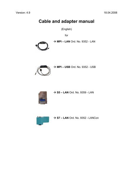
Version: 4.9 18.04.2008<br />
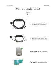
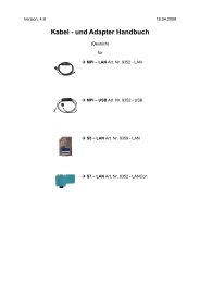
Cable and adapter manual<br />
(English)<br />
for<br />
� MPI – <strong>LAN</strong> Ord. No. 9352 - <strong>LAN</strong><br />
� MPI – USB Ord. No. 9352 - USB<br />
� S5 – <strong>LAN</strong> Ord. No. 9359 - <strong>LAN</strong><br />
� S7 – <strong>LAN</strong> Ord. No. 9352 - <strong>LAN</strong>Con
Table of content<br />
1. MPI – <strong>LAN</strong> Ord. No. 9352 - <strong>LAN</strong> ........................................................................ 4<br />
1.1. Description................................................................................................ 5<br />
1.2. System requirements................................................................................ 5<br />
1.3. Connection possibilities ............................................................................ 6<br />
1.4. Installation ................................................................................................ 9<br />
1.5. Control elements..................................................................................... 10<br />
1.6. Operating instructions............................................................................. 13<br />
1.6.1. Configure the cable ............................................................................. 13<br />
1.6.1.1. By using the cable operating system ............................................... 13<br />
1.6.2. Using the PLC – VCOM software........................................................ 14<br />
1.6.3. Using a PLC software ......................................................................... 14<br />
1.6.4. Merge two PLCs together by using a network..................................... 37<br />
1.6.5. CP – Mode with ProTool/Pro CS v6.00 ............................................... 41<br />
1.6.6. Option Watchdog ................................................................................ 43<br />
1.7. Menu structure........................................................................................ 46<br />
1.8. Technical data ........................................................................................ 51<br />
2. S7 – <strong>LAN</strong> Ord. No. 9352 - <strong>LAN</strong>Con ................................................................. 53<br />
2.1. Description.............................................................................................. 54<br />
2.2. System requirements.............................................................................. 54<br />
2.3. Connection possibilities .......................................................................... 55<br />
2.4. Installation .............................................................................................. 58<br />
2.5. Control elements..................................................................................... 59<br />
2.6. Operating instructions............................................................................. 60<br />
2.6.1. Using the PLC-VCOM software........................................................... 61<br />
2.6.2. Using a PLC software ......................................................................... 62<br />
2.6.3. Direct communication using TCP/IP with Step7© v5.3 (CP mode) ..... 85<br />
2.6.4. Merge two PLCs together by using a network..................................... 97<br />
2.6.5. CP – Mode with ProTool/Pro v6.00 ................................................... 100<br />
2.6.6. Option Watchdog .............................................................................. 102<br />
2.7. Technical data ...................................................................................... 105<br />
3. MPI – <strong>LAN</strong> / S7 – <strong>LAN</strong> <strong>Configuration</strong>............................................................ 106<br />
3.1. By using the Web – Interface................................................................ 106<br />
3.2. Ports ..................................................................................................... 117<br />
4. S5 – <strong>LAN</strong> Ord. No. 9359 - <strong>LAN</strong> ...................................................................... 118<br />
4.1. Description............................................................................................ 119<br />
4.2. System requirements............................................................................ 119<br />
4.3. Connection possibilities ........................................................................ 120<br />
4.4. Installation ............................................................................................ 123<br />
4.4.1. Installation of the Step5© special driver for S5 - <strong>LAN</strong>/PG - USB....... 124<br />
4.5. Control elements................................................................................... 126<br />
4.6. Operating instructions........................................................................... 127<br />
4.6.1. Configure the S5 module .................................................................. 127<br />
4.6.2. Using the PLC-VCOM software......................................................... 128<br />
4.6.3. Using a PLC software ....................................................................... 129<br />
4.6.4. Direct communication with WinCC 6.0 .............................................. 142<br />
4.6.5. S5 – Gateway communication........................................................... 145<br />
4.6.5.1. Specifications of the configuration part.......................................... 147<br />
4.7. Technical data ...................................................................................... 150<br />
4.7.1. Principle Schematics of the S5 – <strong>LAN</strong>............................................... 151<br />
Page 2 Cable and adapter manual © by PI 2008
4.7.2. Ports.................................................................................................. 151<br />
5. MPI – USB Ord. No. 9352 - USB.................................................................... 152<br />
5.1. Description............................................................................................ 153<br />
5.2. System requirements............................................................................ 153<br />
5.3. Connection possibilities ........................................................................ 154<br />
5.4. Installation ............................................................................................ 157<br />
5.5. Control elements................................................................................... 158<br />
5.6. Operating instructions........................................................................... 161<br />
5.6.1. Configure the cable ........................................................................... 161<br />
5.6.2. Using the PLC-VCOM software......................................................... 162<br />
5.6.3. Using a PLC software ....................................................................... 162<br />
5.6.4. Configuring the operator panel by using the MPI – USB cable ......... 181<br />
5.7. Menu structure...................................................................................... 181<br />
5.8. Technical data ...................................................................................... 187<br />
6. PLC – VCom................................................................................................... 189<br />
6.1. Description............................................................................................ 189<br />
6.2. Installation ............................................................................................ 189<br />
6.3. Operating instructions........................................................................... 194<br />
6.4. S5 – <strong>LAN</strong> Manager ............................................................................... 197<br />
6.5. MPI – <strong>LAN</strong> Manager ............................................................................. 200<br />
7. MPI_DP_PPI Driver........................................................................................ 201<br />
7.1. Description............................................................................................ 201<br />
7.2. Installation ............................................................................................ 201<br />
7.3. Interface Assignment ............................................................................ 204<br />
7.4. Properties ............................................................................................. 205<br />
7.5. extended Properties.............................................................................. 207<br />
7.6. Diagnostics ........................................................................................... 208<br />
7.7. Deinstallation ........................................................................................ 208<br />
8. Troubleshooting ............................................................................................ 210<br />
8.1. Frequently Asked Questions................................................................. 210<br />
© by PI 2008 Cable and adapter manual Page 3
1. MPI – <strong>LAN</strong> Ord. No. 9352 - <strong>LAN</strong><br />
Page 4 Cable and adapter manual © by PI 2008
1.1. Description<br />
The MPI – <strong>LAN</strong> cable connects the computer with a MPI - or a Profibus - interface<br />
(PLC) by using a TCP/IP network.<br />
1.2. System requirements<br />
Operating systems<br />
- Windows 98 + SE/ME/NT/2000/XP<br />
Software<br />
- PLC – programming software (e.g. PG2000, Step© 7, S7 for Windows,<br />
Microwin)<br />
- PLC - VCom software (see chapter 6)<br />
Hardware<br />
- Network interface card (NIC) 10/100MBit installed in the computer.<br />
The NIC must provide a RJ – 45 interface. Older network interface card types are often<br />
using BNC interfaces.<br />
© by PI 2008 Cable and adapter manual Page 5
1.3. Connection possibilities<br />
MPI – <strong>LAN</strong> directly connected to the computer.<br />
Page 6 Cable and adapter manual © by PI 2008
MPI – <strong>LAN</strong> connected with the computer using a switch or hub.<br />
© by PI 2008 Cable and adapter manual Page 7
MPI – <strong>LAN</strong> Connection possibilities with operator panel<br />
Page 8 Cable and adapter manual © by PI 2008
1.4. Installation<br />
Hardware<br />
Connect the MPI – <strong>LAN</strong> cable (short side) with the MPI interface (9 pins) of the S7 -<br />
PLC. The network connector from the long side of the cable (RJ – 45) should be<br />
connected as described:<br />
MPI – <strong>LAN</strong> cable to computer:<br />
Connect the network connector from the MPI cable to the network card interface (RJ<br />
– 45) of your computer.<br />
MPI – <strong>LAN</strong> cable to switch/hub:<br />
Connect the network connector of the MPI cable to the uplink port of your switch/hub.<br />
If you are using an auto - negotiated switch you can put the network connector into a<br />
free port of your choice.<br />
MPI – <strong>LAN</strong> with a operator panel:<br />
Connect the cable of the operator panel with the PPI/MPI/PROFIBUS – interface of<br />
the PLC. Connect the MPI – <strong>LAN</strong> cable (short side/9 pin plug) with this interface<br />
(PPI/MPI/PROFIBUS) so that both cables (MPI – <strong>LAN</strong> and Operator Panel) are<br />
plugged into one interface.<br />
Connect the MPI – <strong>LAN</strong> with the network as described above.<br />
There must be a serial communication with the operator panel if this op is new/used at<br />
the first time. Therefore connect your operator panel with the serial COM interface of<br />
your computer. After the communication has been running successfully the panel is<br />
ready to be connected to the PLC.<br />
The PLC supports the cable with power. The cable provides an alternative power<br />
supply interface which can be connected by a 24V/DC adapter (screw clip or a MPI –<br />
net adapter). As soon as the cable is supported with power it shows its software<br />
version on the display and begins to test its internal components.<br />
Software<br />
To communicate with the PLC, please install the PLC - VCom software, as described<br />
in chapter 6.2.<br />
You also need programming software (e.g. PG 2000, Step© 7, S7 for Windows,<br />
Microwin) to work with the PLC.<br />
© by PI 2008 Cable and adapter manual Page 9
1.5. Control elements<br />
a. Keys<br />
b. Default display (Menu Messages)<br />
a. Keys<br />
Key Name Description<br />
� ENTER Change menu and confirm input.<br />
� LEFT Go one menu level back. Cancel input (Input will not be saved).<br />
� RIGHT Select sub menu.<br />
� UP Navigate upwards. Increments a value.<br />
� DOWN Navigate downwards. Decrements a value.<br />
Page 10 Cable and adapter manual © by PI 2008
. Default display (Menu Messages)<br />
First Line<br />
First Line ►#02PD00▀<br />
Second Line ►!02AG04°<br />
Display description from left to right.<br />
#02 � there are two active stations on the MPI – BUS.<br />
PD � letter definition of the PC - Baud rate.<br />
Display Descriptions<br />
PD 115,2k or baud rate recognition is active.<br />
P? Baud rate recognition and access way active.<br />
TD 115,2k or baud rate recognition is active.<br />
(cable is configured as TS – adapter)<br />
PG 19,2k<br />
TS 19,2k (cable is configured as TS – adapter)<br />
Pg 38,4k<br />
Ts 38,4k (cable is configured as TS – adapter)<br />
pG 57,6k<br />
tS 57,6k (cable is configured as TS – adapter)<br />
PM PPIMulti (187,5k)<br />
00 � the station number of the MPI – cable. (Default is „0“)<br />
(In the system configuration click on „Set PG/PC interface“. In the<br />
following dialog click „Properties“. Now you can change in the registry card<br />
„MPI“ the „Address“ of the cable.)<br />
(In the PG 2000 software you can find it by clicking on „Options“ �<br />
„Interfaces“. Near the bottom of the dialog you can change the „local address“<br />
of the cable.)<br />
▀ � if this sign appears in the top of the first line, then the cable is communicating<br />
with the PLC. If this sign appears in the bottom of the first line it is<br />
communicating with the computer.<br />
© by PI 2008 Cable and adapter manual Page 11
Second Line<br />
! (Exclamation mark) � specifies the connection type to the PLC.<br />
Display Description<br />
! Directly connected to the PLC.<br />
? Not direct connected to the PLC.<br />
! (inverse) Directly connected to the PLC with passive block of the PLC.<br />
? (inverse) Not direct connected to the PLC with passive block of the PLC.<br />
02 � is the station number of a connected and active PLC in the MPI - Bus.<br />
Every 750 milliseconds (a ¾ second) another station is displayed, if more than<br />
one has been recognized.<br />
AG � specifies the protocol which is used to communicate with the computer:<br />
Display Description<br />
AG Unknown because there is no connection or an older protocol version<br />
is used.<br />
Ag v5.1 Protocol<br />
ag v5.0 Protocol<br />
04 � Shows the station number of the device, which actual is connected with the<br />
computer software (in this example station number 04).<br />
<strong>Configuration</strong> specific messages.<br />
The menu message is changing while configuring the following baud rates (see<br />
chapter 1.7 Menu structure for detail):<br />
Baud rate – configuration 1. Line 2. Line<br />
PPI 9,6k – (PPISER96) PPISER96 ACTIVE<br />
PPI 19,2k – (PPISER19) PPISER19 ACTIVE<br />
PPI 187,5k – (PPIMulti) ???PM? ????<br />
PPI<strong>LAN</strong> – (PPI<strong>LAN</strong>) PPI<strong>LAN</strong> ACTIVE<br />
PPIUSB – (PPIUSB) PPIUSB ACTIVE<br />
SONDSER SONDSER 19,2 kBaud 8N1<br />
SONDUSB SONDUSB 38,2 kBaud 7E2<br />
Description 8N1:<br />
8 = Data bits<br />
N = Parity<br />
1 = Stop bit<br />
Page 12 Cable and adapter manual © by PI 2008
1.6. Operating instructions<br />
Be sure that your system is supported. If you do not know see chapter 1.2 System<br />
requirements. Also be sure to have connected the cable correctly; otherwise see<br />
chapter 1.3 Connection possibilities and/or chapter 1.4 Installation.<br />
1.6.1. Configure the cable<br />
� #01P? °<br />
!02AG °<br />
�<br />
�<br />
�<br />
�<br />
1.6.1.1. By using the cable operating system<br />
° MENU °<br />
°Config°<br />
°Config°<br />
MPI-BUS°<br />
� °MPI/PPI<br />
Baudrate<br />
�<br />
�<br />
�<br />
�<br />
�<br />
MPI-Baud<br />
° Auto °<br />
°Config°<br />
°PG/PC °<br />
� °PG/PC °<br />
Baudrate<br />
�<br />
�<br />
�<br />
�<br />
�<br />
�<br />
�<br />
PG-Baud°<br />
from PC°<br />
°Config°<br />
°IP adr°<br />
°Config°<br />
SNetMask<br />
Take the cable and press the Enter – Key �. (Control elements<br />
see chapter 1.6).<br />
Navigate with the Up/Down – Keys �� until you reach the Menu<br />
“Config”. Press Enter �.<br />
Search for the submenu „MPI – BUS“. Enter with �.<br />
Press Enter � to configure the “Baudrate”.<br />
Navigate to the entry “Auto” and confirm with �<br />
Press � to return to the “Config” menu. Search for “PG/PC” and<br />
get in with �.<br />
Press � to get in.<br />
Search for the entry “from PC” and press � to set the<br />
configuration.<br />
Go back to the “Config” menu and navigate to “IP adr”. In this<br />
menu you should set a valid IP address. To do so navigate with<br />
the �� keys and set the values with the �� keys.<br />
Confirm your configuration with �.<br />
Back in the “Konfig“ menu the subnet mask must be set. Therefore<br />
got to the entry “SNetMask“ and configure it as described for the<br />
IP address. As soon as you are ready press the enter – key � to<br />
save your configuration.<br />
© by PI 2008 Cable and adapter manual Page 13
Now the cable is ready for work. Just get back to the “Message” menu to see the<br />
status.<br />
1.6.2. Using the PLC – VCOM software<br />
1. Start the PLC – VCom application.<br />
2. Press in the section state in the dialog the button „configure“. The assistant starts.<br />
3. Choose the desired MPI cable and click „OK“ to go on.<br />
4. If the connection is established the chosen cable is shown in the section state and<br />
on the left side you can see the status connected.<br />
If you are having problems with using the PLC – VCom dialog, go to chapter 6.3<br />
Operating instructions of the PLC – VCom description.<br />
The virtual COM-Port is only view-, select- and accessible when the PLCVCOM<br />
is in the „connected“ state, that means a cable is present and usable.<br />
1.6.3. Using a PLC software<br />
a. PG 2000 (v4.41)<br />
b. Set PG/PC interface<br />
c. SIMATIC Step© 7 Manager (v5.2 + SP1)<br />
d. Windows Control Center (WinCC) (v6.0)<br />
e. Windows Control Center flexible 2004 (WinCC flexible) (v5.2.0.0)<br />
f. ProTool/Pro (v6.0 + SP2)<br />
g. Microwin v3.2<br />
h. Microwin v4.0 in the PPI multimaster mode<br />
i. S7 for Windows v5.02<br />
Page 14 Cable and adapter manual © by PI 2008
a. PG 2000 (v4.41)<br />
1. Start the PG 2000 software by using the desktop link<br />
or by using the application entry in the start menu.<br />
2. In the menu „Options“ click „Interfaces“.<br />
3. A dialog appears. In the section „Interface“ you can<br />
configure the „PLC – Interface“ (COM – Port).<br />
4. Configure the baud rate in the section „Bus<br />
access“ to „19,2k“. Below change the value for PC<br />
- MPI to „187,5kBaud“.<br />
5. Save your configuration by pressing „OK“.<br />
6. Now the software is ready to establish a<br />
connection to the PLC. cick the symbol „Open“ and<br />
afterwards press „PLC“. As a alternative action you<br />
can click „File“ � „Open“ � „PLC“.<br />
The connection between PG 2000 and the PLC is now established.<br />
A new window appears. Now you can edit the blocks in the PLC.<br />
© by PI 2008 Cable and adapter manual Page 15
. Set PG/PC interface<br />
This step is important fort he following software<br />
� SIMATIC Step© 7 Manager (v5.2 + SP1)<br />
� Windows Control Center (WinCC) (v6.0)<br />
� Windows Control Center flexible 2004 (WinCC flexible) v5.2.0.0<br />
� ProTool/Pro (v6.0 + SP2)<br />
� Microwin<br />
If the software you are using is not in the list above you can skip setting up the<br />
PG/PC interface.<br />
1. Open the system configuration by using the start<br />
menu.<br />
2. Click on „Set PG/PC interface“.<br />
3. A Dialog with a list box named „Interface Parameter<br />
Assignment Used:” appears. This box should offer<br />
some „PC - Adapter” and/or „TCP/IP” (if you<br />
want to use RFC1006) entries. If you cannot<br />
find these entries go ahead with the steps<br />
PC Adapter or TCP/IP otherwise skip these<br />
steps.<br />
PC - Adapter(Auto, MPI, PROFIBUS)<br />
4. Click on „Choose“ to add these entries to the<br />
PG/PC interface configuration.<br />
5. In this dialog you can deinstall every<br />
installed construction set and install the entries in the „Selection“ box. Choose<br />
„PC - Adapter“ from the „Selection“ box on the left side and click on „Install“. The<br />
chosen construction set will be<br />
installed and a question appears<br />
which asks you to use the<br />
„MPI“ access for the PLC used.<br />
Click „Yes“ if you want to use<br />
the „MPI“ communication type.<br />
Otherwise click „No“ (e.g. if you<br />
want to use the<br />
“PROFIBUS“ communication<br />
type).<br />
Page 16 Cable and adapter manual © by PI 2008
TCP/IP RFC1006 Communication<br />
6. Click on „Choose“ to install the elements required by the RFC1006<br />
communication type.<br />
7. „Choose“ „TCP/IP“ and click on „Install“. If the installation has been successfully<br />
finished „Close” the dialog.<br />
8. Back in the „Set PG/PC interface“ dialog you will now find the desired entries<br />
called „PC - Adapter(Auto)“ (not supported), „PC - Adapter(MPI)“ and „PC -<br />
Adapter(PROFIBUS)“. Now you are able to configure the bus. If you want to use<br />
the „MPI“ communication type go ahead with step b9. Step b12 begins to<br />
describe the „PROFIBUS“ configuration.<br />
MPI configuration<br />
9. A dialog appears. Mark „PC Adapter(MPI)“ Now press „Properties“.<br />
10. In the register card „MPI“ choose the Transmission Rate „187,5 kbit/s“ in the<br />
section „Network Parameters”.<br />
© by PI 2008 Cable and adapter manual Page 17
PROFIBUS configuration<br />
11. The register card „Local Connection“ offers<br />
you the possibility to choose the COM –<br />
Port and to configure the speed of the MPI<br />
cable. Select the virtual COM – Port<br />
created by the PLC - VCom. Now configure<br />
to the list element „Transmission<br />
rate“19200.<br />
12. Select the entry „PC - Adapter(PROFIBUS)“ and click on „Properties“.<br />
13. Set in the registry card „Locale connection“ the<br />
„Connection to:“ parameter to the one simulated<br />
by your PLC - VCom software. (e.g. „COM3“).<br />
Below you can set the „Transmission Rate:“ to<br />
„19200“.<br />
14. Choose the registry card „PROFIBUS“and set<br />
the „Transmission Rate:“ to „187,5kbit/s“. Set the<br />
„Profile:“ to „DP“ („Decentral Peripherie“).<br />
15. Save your settings by pressing the „OK“button<br />
and close the opened „Set PG/PC -<br />
interface“ dialog.<br />
Page 18 Cable and adapter manual © by PI 2008
TCP/IP RFC1006 <strong>Configuration</strong><br />
16. For this communcation type just configure the software you want to use.<br />
The interface settings are completed.<br />
Go ahead with the software you want to use.<br />
ProTool/Pro RunTime (RT) <strong>Configuration</strong><br />
17. If you want to use the ProTool/Pro RunTime (RT)<br />
applikation you can configure the parameters as<br />
shown by using the entry „DPSONLINE“ in the list<br />
box displayed in the upper part of the dialog of the<br />
„Set PG/PC interface” dialog.<br />
c. SIMATIC Step© 7 Manager (v5.2 + SP1)<br />
Please be sure that the interface configuration is correct as described in point b<br />
1. Start your SIMATIC Step© 7 Manager by using the desktop link or the application<br />
entry in the start menu.<br />
the PLC.<br />
2. Click „PLC“. In the drop - down menu click „Display<br />
Accessible Nodes „.<br />
The connection between the SIMATIC S7 Manager and<br />
the PLC is now established.<br />
A new window appears. Now you can edit the blocks of<br />
d. Windows Control Center (WinCC) (v6.0)<br />
Please be sure that the interface configuration is correct as described in point b<br />
1. Start WinCC by using the desktop link or the program entry in the start menu.<br />
2. Choose „New” in the menu „File” or click on the white („letter”) symbol to start a<br />
new project.<br />
© by PI 2008 Cable and adapter manual Page 19
3. The next dialog offers you several project types<br />
„Single - User Project“, „Multi - User Project“ and<br />
„Client Project“. The next steps are describing the<br />
„Single - User Project“.<br />
If you are using „Multi - User“ - or „Client“ - Project<br />
please read the WinCC manual for detail.<br />
4. “OK“ leads you to a new dialog. Type in the „Project Name“ and the „Subfolder“ of<br />
the „Project Path“. With „Create“ the<br />
chosen configuration is confirmed.<br />
6. For a proper working communication<br />
with the PLC there must be defined<br />
how the software has to<br />
communicate with the PLC.<br />
Therefore right click on „Tag<br />
Management“ to open the context<br />
menu. Choose „Add New Driver ...“.<br />
5. Please wait until the project is created.<br />
Afterward the project content is shown<br />
in the left part of the main window.<br />
7. In the „Add new driver“ dialog select the driver which fits to your PLC. For a S7<br />
PLC choose „SIMATIC S7 Protocol Suite.chn“. If you are using a different PLC<br />
please inform yourself which driver fits with your PLC.<br />
It is important that the chosen driver fits with the PLC otherwise the connection cannot<br />
be established.<br />
Page 20 Cable and adapter manual © by PI 2008
8. Now you should expand in the „Tag Management“ the branch SIMATIC S7<br />
PROTOCOL SUITE. A lot of protocols for different connection types will appear.<br />
General method for creating a new connection is: Right click on the desired<br />
connection (MPI - > Picture: „MPI“, TCP/IP - > Picture: „TCP/IP“). A context<br />
menu opens. Click on „New Driver Connection…”. This manual describes two<br />
connection configurations. MPI (step 9) and TCP/IP (step 10 – 17).<br />
Picture: MPI Picture: TCP/IP<br />
MPI<br />
9. Now you are able to type in the name of the<br />
connection. With a click on „<strong>Configuration</strong>“ a new<br />
dialog will appear. Set up the station address of<br />
the PLC (in this example „2“).<br />
TCP/IP<br />
10. A dialog appears where you can configure the<br />
connection parameters. Set up the IP - Address<br />
of the MPI - <strong>LAN</strong> cable and configure the rack<br />
number as well as the slot number.<br />
Confirm this configuration by pressing<br />
„OK”. (Example configuration: IP -<br />
Address: 192.168.1.55, Rack -<br />
Number: 0, Slot - Nr.: 2)<br />
11. With a right click on the new<br />
connection you can start the<br />
properties dialog. In this dialog<br />
please click on properties.<br />
© by PI 2008 Cable and adapter manual Page 21
12. In the properties of the channel unit you<br />
can see all „available connections”.<br />
Choose the newly created one and click<br />
again on „Properties”. Now you can see<br />
all the variables which has been<br />
created for this connection. In fact this<br />
connection is a new one so there will be<br />
no variable in the list. To add a new<br />
variable click on „New”.<br />
13. Now set up the name of the variable<br />
(e.g. „S7<strong>LAN</strong>_MW0”) and other<br />
configuration data. Our example has<br />
the following configuration: Name:<br />
„S7<strong>LAN</strong>_MW0“, Data type: „unsigned<br />
16 - Bit value“, Length: „2“, Address: „MW0“, Format adaptation:<br />
„WordToUnsignedWord“. Click on „Choose” beside the Address to define the<br />
address from the variable. Example configuration: The data area from the variable<br />
is set to „Mark“ and the address is set to „Word”. The edit box „MW“ is set to „0”.<br />
14. Confirm all open dialogs with „OK“.<br />
15. The connection needs to know which network interface card it should use to send<br />
data via the Ethernet. Open the „System parameters“ dialog from the context<br />
menu (right click on TCP/IP).<br />
16. Choose the registry card „Unit“ and set the „logical device name“ to your network<br />
interface card (usually the name of the NIC begins with a „TCP/IP - > „).<br />
17. Confirm with „OK“.<br />
Now you are able to start the communication. Stop it by pressing<br />
Page 22 Cable and adapter manual © by PI 2008
To clean up errors faster the WinCC Software offers a tool named „Channel<br />
Diagnosis”. This tool analyses all connections from your WinCC software. For<br />
demonstration purposes please stop the newly started connection from your WinCC<br />
explorer.<br />
18. Start the software „Channel Diagnosis“ using your link in the start menu.<br />
19. The tool could not detect a running connection so it marked the connection/s with<br />
a red ‘X’ (registry card „Channels/Connections“). Click on the newly created, not<br />
active connection (with the red ‘X’) and some information from the connection will<br />
appear in the right part of the dialog. One of these counters is called „Last Error<br />
Code“.<br />
© by PI 2008 Cable and adapter manual Page 23
20. Click with the right mouse key on this counter and choose „Help” from the context<br />
menu. A yellow window appears (tooltip) with detailed error description.<br />
21. Lets see what happens if the connection runs properly. Start the connection from<br />
your WinCC Explorer. The „Channel Diagnosis“ dialog marks the connection with<br />
a green hook.<br />
Page 24 Cable and adapter manual © by PI 2008
e. Windows Control Center flexible 2004 (WinCC flexible) v5.2.0.0<br />
Please be sure that the interface configuration is correct as described in point b<br />
1. Start the WinCC flexible 2004 software by using the desktop link or the program<br />
entry in the start menu.<br />
2. At first click on „Create an empty project“ in the „Start page“.<br />
3. In the „Device selection“mark the<br />
used operator panel (example: „TP<br />
170A“)and confirm with „OK“.<br />
4. After the project has been created<br />
right click in the project window on<br />
„Connections“ of the sub menu<br />
„Communication“. In the context<br />
menu click on „Add Connection“.<br />
5. A new configuration window opens in the right part of the main window. Important<br />
for a working connection is:<br />
� the communication driver (set up which PLC you are using (example:<br />
„SIMATIC S7 300/400“))<br />
� the Baud rate (configure the baud rate you have already configured to the<br />
PG/PC interface (e.g. „187500“))<br />
� the address of the terminal (HMI) (in this example „1“)<br />
� the Profile („MPI“ for example)<br />
� the Highest Station Address (HSA) (e.g. „126“)<br />
� the address of the PLC (e.g. „2“)<br />
(see picture on next page)<br />
© by PI 2008 Cable and adapter manual Page 25
6. Now you can start with your work. If you have<br />
finished work you can transfer this project to<br />
the panel by reading the next steps.<br />
7. Choose „Transfer Settings“ from the sub<br />
menu „Transfer”.<br />
8. In the new dialog change the „Mode“ to<br />
„MPI/DP“ and set the „Station address“ of the<br />
operator panel (e.g. „1“). If desired you can switch the „Delta transfer“ to „On” (in<br />
this example we set it „Off”).<br />
Page 26 Cable and adapter manual © by PI 2008
9. Press the button „Transfer“ to start communication with the terminal. Your project<br />
is about to be transferred.<br />
The WinCC flexible software is now able to communicate with your operator panel.<br />
© by PI 2008 Cable and adapter manual Page 27
f. ProTool/Pro v6.0 SP2<br />
Please be sure that the interface configuration is correct as described in point b<br />
1. Start ProTool/Pro by using the desktop link or program entry in the start menu.<br />
2. Choose from the menu „File“ the sub menu „New“ or click on the right symbol.<br />
3. The next dialog askes you which<br />
operator panel you are using. Mark the<br />
used panel (e.g. „TP 170A“)<br />
4. „Next“ leads you to a new dialog. Type<br />
in the specfic fields the name of the<br />
PLC device and choose the used PLC<br />
in the driver selection (e.g. „SIMATIC<br />
S7 – 300/400 V6.0“).<br />
5. Via „Parameter...“ you are calling an<br />
configuration dialog from the chosen<br />
PLC driver. Set up the station address<br />
of the panel (example „1“) and of the PLC<br />
(example „2“). In the sector „Net<br />
parameter“ choose the interface which uses<br />
your cable on the PLC (e.g. „MPI“).<br />
Configure the baud rate to „187.5“.<br />
6. The button „More ...“ leads you to a small<br />
dialog where the „Highest Station<br />
Address“ should be configured to „126“. Set<br />
up the „Number of masters“ (e.g. „1“) and<br />
confirm with „OK“ until you got back to the „Control Selection“.<br />
7. Go on with „Next“.<br />
9. Confirm with<br />
„OK“ and<br />
start with<br />
your work. If<br />
you have finished working on this project you can go on<br />
with the next steps.<br />
8. In the main window start the Transfer<br />
Settings dialog by clicking on „File“ �<br />
„Transfer“ � „Settings...“. Choose „MPI<br />
/ PROFIBUS DP“ from the listbox and<br />
type in the station address of the<br />
operator panel (e.g. „1“).<br />
Page 28 Cable and adapter manual © by PI 2008
10. If you want to transfer you project to the panel you have to generate<br />
the project first. This can be done with a click on „File“ � „Compile“.<br />
11. To transfer the project just click on „File“ � „Download“ „Start<br />
Project Download“ or click on the right symbol .<br />
12. Please wait while the project is transferred.<br />
The communication between the operator panel is now<br />
established.<br />
© by PI 2008 Cable and adapter manual Page 29
g. Microwin v3.2 (only for S7 200)<br />
Please be sure that the interface configuration is correct as described in point b<br />
1. Start the Microwin software by using the desktop link or the<br />
program entry in the start menu.<br />
2. Click on „Type“ in the menu „PLC”. Configure the „PLC<br />
Type“ (e.g. „CPU 224“) as well as the „CPU Version“ (e.g.<br />
„01.22”) to the dialog.<br />
3. Click on „Communications...” to start the next dialog. In the sector „Address” set<br />
up the „Remote” listbox with the station address of the PLC (e.g. „2”).<br />
Page 30 Cable and adapter manual © by PI 2008
If you skipped the point b („Set up PG/PC interface“) you can configure the PG/PC<br />
interface with a click on „Set PG/PC interface“.<br />
4. In the right part of the dialog double click on the blue arrow symbol to test the<br />
communication with the PLC.<br />
5. The sector „Address“ should be updated and displays the „PLC Type”. Also the<br />
CPU of the PLC is displayed in the right part of the dialog.<br />
6. Confirm with „OK“ until you get back to the main window.<br />
The communication with the PLC ist now established.<br />
© by PI 2008 Cable and adapter manual Page 31
h. Microwin v4.0 using the PPI Multimaster mode<br />
Please be sure that the interface configuration is correct as described<br />
in point b<br />
The PPI Multimaster mode has been developed for the purpose that multiple devices<br />
can communicate parallel with one PLC. The following steps describe how to<br />
configure this mode.<br />
1. The cable must be set to PPIMulti mode. Therefore go to the „Config” menu.<br />
2. Set it to „PPIMulti“ with the cursors of the cables case and press return to confirm<br />
this configuration. The menu „Messages” (first menu) displays now „PM“ in the<br />
first line.<br />
3. Now you have to set the PG/PC interface. You can do this by using the Microwin<br />
software. Start the Microwin software.<br />
4. Click on „Set PG/PC Interface“ at the left side of the applikation window. See the<br />
picture on the right for further details.<br />
5. Choose the entry „PC/PPI cable(PPI)“ and click on „Properties”.<br />
6. In the registry path „PPI“ you can for example the „HSA“.<br />
Page 32 Cable and adapter manual © by PI 2008
7. In the registry path „Local Device“set the COM Port („Connection to”) to the one<br />
provided by the PLC VCom software.<br />
8. Confirm your settings with „OK“ and click on „Communications” above the „Set<br />
PG/PC Interface” Button you have used before.<br />
© by PI 2008 Cable and adapter manual Page 33
9. Click on „Double click to Refresh „. Now the software is searching for the PLC.<br />
10. If the PLC could be found the dialog changes as shown in the picture below:<br />
Page 34 Cable and adapter manual © by PI 2008
i. S7 for Windows v5.02<br />
Please be sure that the interface configuration is correct as described in point b<br />
1. Start the „S7 for Windows” software by using the link on your<br />
desktop or use the link in your start menu (standard is<br />
„Programs\S7 for Windows\S7 for Windows“)<br />
2. Choose File - >Preferences... to configure the communication<br />
configuration between the computer and the PLC.<br />
3. A new dialog appears which provides to set up a lot of<br />
configuration data about the communication with your PLC.<br />
4. Choose the first registry card „Interface“ (standard) and set up the configuration<br />
data as descriped below:<br />
� Area: „Preferences from:“ � PC<br />
� Area: „PLC Type:“ � S7<br />
� Area: „Protocol:“ � MPI - Umsetzer<br />
� Area: „Serial Port:“ � Choose the virtual COM port which has been<br />
created by PLC - VCom (e.g. „COM 4”).<br />
� Area: „Baud Rate“ � Choose the speed you want to use at the bus (e.g.<br />
„115200“)<br />
� Area: „MPI Converter:“<br />
o Activate the checkbox „Only Master at the Bus“ if you have only one<br />
PLC in the bus.<br />
o Leave the fields „ S7W MPI Address“ and „MPI Address PLC“ as it is.<br />
o The number in the listbox „Max MPI Address“ must be higher than the<br />
PLC with the highest station address in your MPI bus. Otherwise every<br />
PLC which is higher than this number will not been seen (e.g. if there is<br />
only one PLC in your bus „15“ is more than enough).<br />
© by PI 2008 Cable and adapter manual Page 35
5. After the software is configured and the PLC - VCom is<br />
connected with the PLC, please click „Select PLC” in the<br />
area „MPI Converter“. A new dialog appears where you<br />
can select the desired PLC. While this dialog opens you<br />
can see right now (in the bottom right of the task bar) the<br />
green blinking PLC VCom icon . This means that the<br />
software is already talking to the PLC.<br />
6. The dialog displays all the PLCs that can be found in your MPI bus. Select the<br />
desired one and confirm with „OK”.<br />
7. Close the preferences dialog by pressing the „OK“ button.<br />
8. Back in the main window press the „PC Block List“ button for<br />
testing the new established communication configuration.<br />
9. Please wait a moment for the software to read the desired blocks<br />
from the PLC. The blocks will be displayed in the listbox below<br />
the menu bar (see picture to the right).<br />
The communication between the software and your PLC is<br />
established.<br />
If you had any trouble up to this point go ahead in chapter 8.1<br />
Frequently Asked Questions.<br />
Page 36 Cable and adapter manual © by PI 2008
1.6.4. Merge two PLCs together by using a network<br />
By merging two PLCs together you will be able to transfer data from one PLC to<br />
another. Merging PLCs together is only possible with two S5/S7 PLCs or one S5 PLC<br />
connected with a S7 PLC.<br />
Each MPI – <strong>LAN</strong> cable can establish up to 8 connections. A S5 - Gateway up to 2.<br />
For this example we have merged a S7 with a S5 PLC.<br />
As an interface between S7 and S5 the MPI – <strong>LAN</strong> cable and the S5 – Gateway<br />
module have been used.<br />
MPI – <strong>LAN</strong> <strong>Configuration</strong><br />
The MPI – <strong>LAN</strong> cable can be configured by using the Web interface (see chapter 3.1)<br />
or by using the keys on the device.<br />
Menu Call the main menu by pressing � in the start screen.<br />
Message<br />
Menu By pressing the cursor key � or � you can select the submenu<br />
Config “Config” and get in with �.<br />
Config Select the menu “S7onS7S5” by using the keys � or � and confirm<br />
S7onS7S5<br />
Connect.<br />
00<br />
with �<br />
Set the desired connection (0 … 7) (��) and confirm with �. The<br />
connection number will always be displayed in the right top corner.<br />
(Except by setting the IP address because it uses too much space).<br />
Now you have got a few more configurations to do.<br />
<strong>Configuration</strong>/<br />
Submenu<br />
Description<br />
Type Connection type<br />
CPU No Locale Partner station<br />
DB No Communication data block<br />
DW No Start of the communication range in the given communication data<br />
block.<br />
IP Addr Set up the IP address of the partner.<br />
TSAP TSAP<br />
Polltime Poll time<br />
Type<br />
First Line: Type 00<br />
Second Line:<br />
Type Description<br />
OFF Connection is not used.<br />
DBActive (*1) Establishes the connection by using the TCP protocol.<br />
DBPassiv (*1) Waits until another device establishes the connection.<br />
S7Active (*2) Establishes the connection by using the TCP protocol.<br />
S7Passiv (*2) Waits until another device establishes the connection.<br />
(*1) DB Active and Passive are using the function blocks FC 55 (send) and FC 56 (receive) for data<br />
exchange.<br />
(*2) S7 Active and Passive are using a special bridge function for the data exchange.<br />
© by PI 2008 Cable and adapter manual Page 37
CPU No<br />
First Line: CPU 00<br />
Second Line: 24<br />
Enter the station number of the PLC which is used for the data exchange.<br />
DB No<br />
First Line: DBNo 00<br />
Second Line: 000010<br />
Enter the number of the data block which is used for the communication.<br />
DW No<br />
First Line: DWNo 00<br />
Second Line: 000010<br />
Enter the starting data byte of the desired data block.<br />
IP Addr<br />
First Line: 1
Data exchanging with the help of the data blocks<br />
� Structure of the communication data block<br />
Data bytes Access type Description<br />
00 – 09 Read Receive area. At this place the data received over the<br />
network will be saved.<br />
10 – 19 Write Send area. At this place the data will be send over the<br />
network.<br />
20 – 30 Read, Write Length, status and control byte for the send or receive<br />
area.<br />
HINT: TXLen defines the real length of data which will be send. RXLen contains the number of bytes<br />
received.<br />
� Format of TXERRRDY and RXERRRDY<br />
These bytes are containing the transfer status.<br />
Bit Status Description<br />
0 1 Start of the transfer (TXERRRDY).<br />
Receiving allowed (RXERRRDY).<br />
1 1 An error occurred.<br />
2 1 Transfer completed (TXERRRDY).<br />
Received data (RXERRRDY).<br />
3 – 7 ? Reserved<br />
� Usable data types<br />
The following values are possible with the data types TX.TYP and RX.TYP.<br />
Values Type Responsible data types<br />
‚D’, ‚d’<br />
Data block TX.DBNR, RX.DBNR<br />
Byte of the data block TX.DWNR, RX.DWNR<br />
‚E’, ‚e’, ‚I’, ‚i’ Reception byte TX.DWNR, RX.DWNR<br />
‚A’, ‚a’, ‚Q’, ‚q’ Output byte TX.DWNR, RX.DWNR<br />
© by PI 2008 Cable and adapter manual Page 39
‚M’, ‚m’, ‚F’, ‚f’ Keeping byte TX.DWNR, RX.DWNR<br />
‚T’, ‚t’ Timer TX.DWNR, RX.DWNR<br />
‚Z’, ‚z’, ‚C’, ‚c’ Counter TX.DWNR, RX.DWNR<br />
� Status values (TXSTATUS, RXSTATUS)<br />
Status values Description<br />
0000h Instruction completed<br />
7000h Instruction will not be processed.<br />
80B0h Construction component does not know the record.<br />
80B1h Wrong length in the parameter.<br />
80C3h Memory temporary used.<br />
80C4h Communication error.<br />
8183h Project planning’s not available or service has not been started yet.<br />
8184h Data type or source data range is wrong.<br />
8185h Length exceeds the maximum size of the source data range or the<br />
destination data range is too small.<br />
� Function blocks<br />
o FC 55 (S7<strong>LAN</strong>_SEND)<br />
o FC 56 (S7<strong>LAN</strong>_RECV)<br />
These function blocks are used to send and receive data.<br />
Page 40 Cable and adapter manual © by PI 2008
1.6.5. CP – Mode with ProTool/Pro CS v6.00<br />
Used Software: ProTool/Pro CS v6.00 SP2<br />
1. Creating a new project<br />
Start the ProTool/Pro CS software and click on File � New. (for more Information<br />
about creating projects with ProTool/Pro CS v6.00 read the manual of the developer).<br />
2. Choosing a destination device<br />
The destination device must support the Ethernet interface.<br />
3. Choosing a PLC<br />
Enter a typical PLC Name and select the used PLC type (e.g. „SIMATIC S7 300/400<br />
V6.0“). After choosing the PLC type click on parameter.<br />
OP parameter<br />
Interface If the desired destination device supports “Ethernet” you<br />
can change the interface to “Ethernet”.<br />
Protocol Communication is established by using the IP protocol.<br />
Address Enter the IP address of your computer.<br />
Subnet mask Enter the subnet mask of your computer.<br />
Routing Activate this check box to reach members outside your<br />
subnet. Requires that the construction components of<br />
© by PI 2008 Cable and adapter manual Page 41
the station supports routing (CPUs und CPs). More<br />
information you will get in the "STEP 7 Online Help".<br />
Parameter of the partner<br />
Address Enter the IP Address of the MPI – <strong>LAN</strong> cable which is<br />
plugged onto the PLC.<br />
Slot Enter the slot number of the destination CPU.<br />
Construction<br />
Enter the construction components.<br />
components<br />
Cyclic operation If this check box is active the PLC optimizes the<br />
operation between ProTool/Pro Runtime and the PLC.<br />
This is used to get a better performance. For Parallel<br />
operations of more than one computers the cyclic<br />
operation check box should be deactivated.<br />
Confirm the configuration with “OK“.<br />
4. Complete the project<br />
Click on “Next“ and then on “Complete“ to end the project start configuration.<br />
5. Alternative configuration<br />
If you select the group “Controls“ in the left part of the window you can see the<br />
available PLCs in the right part. Right click with the mouse button on the PLC and<br />
select “Properties” in order to get back to the configuration dialog we used in the<br />
project configuration at the beginning.<br />
At least to get there you have to click<br />
on “Parameter“.<br />
6. Transfer properties<br />
In the file menu click on „Transfer“ �<br />
„Properties…“ and the following dialog<br />
appears.<br />
Choose “Ethernet“ so that the<br />
connection can be established in the<br />
CP mode.<br />
If “Ethernet“ is activated you can enter<br />
the “IP address“ of the destination<br />
device (MPI – <strong>LAN</strong>). Confirm with<br />
“OK“ to complete the configuration.<br />
7. <strong>Configuration</strong> is complete<br />
Now you can transfer the project.<br />
Page 42 Cable and adapter manual © by PI 2008
1.6.6. Option Watchdog<br />
With this Option (you must buy it to use it) you could continueosly check the<br />
MPI/Profibus. The Number of detected Parity errors and Spikes are counted and<br />
saved into a 8 Bit Register. This Register could then be read from the PC or<br />
displayed by a WebBrowser. Try to use the special WebSide „WD.HTM“, the<br />
following Output is displayed.<br />
This side will refresh every second after completely loaded. The Counters are always<br />
reset to 0 when read.<br />
You could also access the S7/MPI-<strong>LAN</strong> directly. Start in a Command-Shell<br />
„telnet 192.168.1.56 133“ and Press . Telnet will establish a connection to<br />
the S7/MPI-<strong>LAN</strong> with the IP-Address 192.168.1.55 and on Port 133 (Statistic Service),<br />
a blank screen is displayed:<br />
© by PI 2008 Cable and adapter manual Page 43
The S7/MPI-<strong>LAN</strong> sends only data when something is recieved on the open TCP/IP<br />
Socket on Port 133 (regardless of the length).<br />
Press now the -Key several times, then the S7/MPI-<strong>LAN</strong> will response with<br />
some data:<br />
The Structure of the recieved data is descriped in the next table::<br />
Data Description<br />
30h<br />
30h<br />
31h<br />
00h<br />
32h<br />
35h<br />
35h<br />
00h<br />
Parity – Counter as ASCII-Text, including leading Zeros and ending ‚\0’<br />
here „001“<br />
Spike - Counter as ASCII-Text, including leading Zeros and ending ‚\0’<br />
here „255“<br />
01h Binary Parity – Counter (8 Bit)<br />
FFh Binary Spike - Counter (8 Bit)<br />
On the MEGA-ToolBox CD is also a console-application including source which<br />
shows an example of access to S7/MPI-<strong>LAN</strong>.<br />
// WDTest.cpp : Definiert den Einsprungpunkt für die Konsolenanwendung.<br />
//<br />
#include "stdafx.h"<br />
typedef struct {<br />
unsigned char ucASCIIParity[4]; // Anzahl Paritätsfehler seit letzter Abfrage<br />
// 3 Ziffern mit abschließender '\0'<br />
unsigned char ucASCIISpikes[4]; // Anzahl erkannter Spikes seit letzter Abfrage<br />
// 3 Ziffern mit abschließender '\0',<br />
unsigned char ucBINParity; // Binärwert der Anzahl Paritätsfehler<br />
unsigned char ucBINSpikes; // Binärwert der Anzahl Spikes<br />
} S7<strong>LAN</strong>INFO;<br />
Page 44 Cable and adapter manual © by PI 2008
int main(int argc, char* argv[])<br />
{<br />
SOCKET sS7<strong>LAN</strong>;<br />
DWORD dwTimeout = 1000L; // 1 Sekunde Timeout<br />
int NaggleOn = 1;<br />
struct sockaddr_in sS7<strong>LAN</strong>Adr;<br />
struct linger sLinger;<br />
S7<strong>LAN</strong>INFO sInfo;<br />
WSADATA sWSAData;<br />
printf("S7<strong>LAN</strong> Watchdog Test V1.00\n\n");<br />
memset(&sInfo,0,sizeof(sInfo));<br />
if (WSAStartup(MAKEWORD(1,1),&sWSAData) != 0) {<br />
printf("WSA Startup fehlerhjaft => Abbruch\n");<br />
return(0);<br />
}<br />
sS7<strong>LAN</strong> = socket(AF_INET, SOCK_STREAM, 0); //0<br />
if (sS7<strong>LAN</strong> != INVALID_SOCKET) {<br />
// Sende/Empfangstimeout einstellen<br />
setsockopt( sS7<strong>LAN</strong>, SOL_SOCKET, SO_SNDTIMEO,(char *)&dwTimeout, sizeof(dwTimeout));<br />
setsockopt( sS7<strong>LAN</strong>, SOL_SOCKET, SO_RCVTIMEO,(char *)&dwTimeout, sizeof(dwTimeout));<br />
// Naggle-Algorithmus aus<br />
setsockopt(sS7<strong>LAN</strong>, IPPROTO_TCP, TCP_NODELAY,(char*) &NaggleOn, sizeof(NaggleOn));<br />
sS7<strong>LAN</strong>Adr.sin_family = AF_INET;<br />
sS7<strong>LAN</strong>Adr.sin_port = htons(133); // Port 133; Statistic Service<br />
sS7<strong>LAN</strong>Adr.sin_addr.S_un.S_un_b.s_b1 = 192; // IP-Adresse des S7<strong>LAN</strong>'s<br />
sS7<strong>LAN</strong>Adr.sin_addr.S_un.S_un_b.s_b2 = 168;<br />
sS7<strong>LAN</strong>Adr.sin_addr.S_un.S_un_b.s_b3 = 1;<br />
sS7<strong>LAN</strong>Adr.sin_addr.S_un.S_un_b.s_b4 = 56;<br />
if (connect(sS7<strong>LAN</strong>, (struct sockaddr *)&sS7<strong>LAN</strong>Adr, sizeof(sS7<strong>LAN</strong>Adr)) != SOCKET_ERROR) {<br />
// etwas senden => daraufhin ende S7<strong>LAN</strong> antwort<br />
send(sS7<strong>LAN</strong>, (const char *) "A", 1, 0);<br />
// Daten vom S7<strong>LAN</strong> empfangen<br />
if (recv(sS7<strong>LAN</strong>, (char *)&sInfo, sizeof(sInfo), 0)) {<br />
printf("Parity: %s Spikes: %s\nParity: %3d Spikes:<br />
%3d\n",&sInfo.ucASCIIParity[0],&sInfo.ucASCIISpikes[0],(unsigned int)<br />
sInfo.ucBINParity,(unsigned int) sInfo.ucBINSpikes );<br />
} else {<br />
printf("Empfang vom S7<strong>LAN</strong> gestört\n");<br />
}<br />
}<br />
sLinger.l_linger = 0;<br />
sLinger.l_onoff = 1; // unmittelbar schlieîen<br />
shutdown(sS7<strong>LAN</strong>,2); // Read and Write<br />
setsockopt(sS7<strong>LAN</strong>, SOL_SOCKET, SO_LINGER, (char *)&sLinger, sizeof(sLinger));<br />
closesocket(sS7<strong>LAN</strong>);<br />
} else {<br />
printf("S7<strong>LAN</strong> nicht ereichbar\n");<br />
}<br />
} else {<br />
printf("Socket nicht öffenbar\n");<br />
}<br />
return 0;<br />
© by PI 2008 Cable and adapter manual Page 45
1.7. Menu structure<br />
a. Graphical Description<br />
b. Info<br />
c. Bus<br />
d. Config<br />
The menu messages are described in the previous chapter 1.6 Operating instructions.<br />
Also it is recommended that you are involved in using the MPI cable. See chapter 1.6<br />
Control Elements for being involved.<br />
a. Graphical Description<br />
With � you will get in the menu of the cable. This menu has the following structure.<br />
° MENU °<br />
Message°<br />
Standard display<br />
(Status)<br />
� ° MENU °<br />
°Config°<br />
� ° MENU °<br />
° Bus °<br />
<strong>Configuration</strong> BUS display<br />
� °Config°<br />
° Mode °<br />
� ° Bus °<br />
Address°<br />
� ° MENU °<br />
° Info °<br />
Cable information<br />
� ° Info °<br />
Version°<br />
Cable mode Bus address OS Version<br />
� °Config°<br />
Password<br />
<strong>Configuration</strong><br />
password<br />
� °Config°<br />
°Reset °<br />
Cable reset<br />
� °Config°<br />
Set Def.<br />
Sets the<br />
configuration to<br />
default<br />
� °Config°<br />
Language<br />
Language<br />
� °Config°<br />
S7toS5S7<br />
<strong>Configuration</strong> for<br />
the data exchange<br />
of two PLCs<br />
� °Config°<br />
Protocol<br />
Protocol which is<br />
used on the bus<br />
� °Config°<br />
°PG/PC °<br />
PG interface<br />
settings<br />
Page 46 Cable and adapter manual © by PI 2008
� °Config°<br />
MPI-BUS°<br />
MPI interface<br />
settings<br />
� °Config°<br />
°IP adr°<br />
IP address of the<br />
cable<br />
� °Config°<br />
SNetMask<br />
Subnetmask of the<br />
cable<br />
� °Config°<br />
Gateway°<br />
Gateway<br />
� °Config°<br />
°DHCP °<br />
De-/Activates the<br />
DHCP client<br />
� °Config°<br />
°Data °<br />
Un-/locks<br />
configuration send<br />
by the computer.<br />
b. Info<br />
Select the menu “Info“ to choose, by pressing the Enter – Key �, the sub menu<br />
“Version“. This menu shows you the operating system version of the cable.<br />
c. Bus<br />
Select the menu “Bus“ to choose, by pressing the Enter – Key �, the sub menu<br />
“Address “. With the Up/Down – Keys �� you can find the connected stations.<br />
The menu “Address “:<br />
° Bus °<br />
Address°<br />
The letters in the second line are describing the station:<br />
Letter Description<br />
D The MPI cable is directly connected to<br />
the PLC.<br />
A This station is active in the bus.<br />
P This station is passive in the bus, for e.g.<br />
some OP’s, FM – blocks also MPI Bus –<br />
Slaves.<br />
The numbers are the address of the station.<br />
© by PI 2008 Cable and adapter manual Page 47
d. Config<br />
o Mode<br />
o Password<br />
o Reset<br />
o Set Def.<br />
o Language<br />
o S7toS5S7<br />
o Protocol<br />
o PG/PC<br />
o MPI – BUS<br />
o IP Adr<br />
o SNetMask<br />
o Gateway<br />
o DHCP<br />
o Data<br />
• Mode<br />
Choose this menu to change the cables way of working.<br />
Available selections: “MPI – <strong>LAN</strong>“ – Normal MPI – <strong>LAN</strong> mode<br />
“PPIMulti“ – S7 200 Multimaster mode<br />
“PPI<strong>LAN</strong>19“ – S7 200 PPI 19.2KBaud<br />
“SOND_<strong>LAN</strong>“ - Special <strong>LAN</strong> baud rate<br />
“SOND_SER“ – Special Serial baud rate<br />
“PPI<strong>LAN</strong>96“ – S7 200 PPI 9.6KBaud<br />
• Password<br />
Choose this menu to change the password of the cable – configuration.<br />
(Default: “0“).<br />
• Reset<br />
Press � to perform a system reset.<br />
• Set Def.<br />
Press the Enter – Key � to load the default configuration.<br />
• Language<br />
In this sub menu you can choose your desired language.<br />
Available selections “German“ und “English“.<br />
• S7toS5S7<br />
This menu is to configure connections to other PLCs. To get more information read<br />
chapter 1.6.2.<br />
Page 48 Cable and adapter manual © by PI 2008
• Protocol<br />
Change the protocol version. Choose “Auto“ if you want that the cable takes the<br />
configuration from the PG. If you experience any trouble on the bus change the<br />
protocol to “V5.0 Old”. Because this is version is more stable (but slower) than the”V<br />
5.1” protocol.<br />
• PG/PC<br />
In this menu you can change the connection speed between the programming device<br />
and the computer. This works only by using a MPI – II (Ord. No. 9352) cable with the<br />
serial plug connected to the computer.<br />
Available baud rates: “2400“, “4800“, “9.6k“, “19.2k“, “38.4k“, “57.6k“, “115.2k“.<br />
If you are using “from PC“ the cable takes the PG configuration.<br />
• MPI – BUS<br />
You have to choose between these sub menus.<br />
- Baudrate<br />
- Master<br />
- local No<br />
- HSA<br />
- Profile<br />
- CP-Mode<br />
- Baudrate<br />
Change the speed of the MPI/Profibus - Bus.<br />
Available baud rates: “Auto“, “19,2k“, “45,45k“, “93,75k“, “187,5k“,<br />
“500k“, “1,5M“, “3M“, “6M“, “12M“.<br />
HINT: The baud rates “3M“, “6M“ and “12M“ can only be configured by cable. These higher baud rates<br />
(from “3M” to “12M”) will be overwritten by the PC. To get sure that this will not happen configure (in<br />
the cables menu) “Lock” in the sub menu “Data”. (This sub menu is also described at the bottom of the<br />
next page)<br />
- Master<br />
In the case that the cable is connected with only one passive station, configure<br />
“Master” to the cable to determine that the cable is configuring itself. In all other<br />
cases please configure “Multimaster“ to the cable.<br />
- local No<br />
Changes the station number of the cable. Hexadecimal values of “00“ to “7E“ are<br />
available.<br />
© by PI 2008 Cable and adapter manual Page 49
- HSA<br />
HSA stands for Highest Station Address. Configure the highest station number to the<br />
cable which is connected to the MPI bus. Possible values: “from PC“, “15“, “31“, “63“,<br />
“126“.<br />
If you are using “from PC“ the cable takes the PG configuration.<br />
- Profile<br />
Select “Standard“ to use the standard PROFIBUS mode. “DP“ (Decentral Peripherie),<br />
“DP/FMS“ (Field Message System) and “MPI“ (Multi Point Interface) are deviations of<br />
the PROFIBUS standard.<br />
- CP-Mode<br />
Sets the CP mode configuration. Sets the following options:<br />
Keep in mind that alle except the StatNo will be set automatically while<br />
communicating.<br />
Option Description<br />
StatNo PLC number.<br />
SlotNo Automatic. Slot number of the PLC.<br />
Function Automatic. Enter the correct communication.<br />
0 = Not defined.<br />
1 = Operating terminal communication.<br />
2 = PG communication.<br />
3 = Step7 basis communication.<br />
• IP Adr<br />
Changes the IP address of the cable. With the cursor > < you can move from<br />
number to number. At least there are 4 x 3 numbers to change for a valid IP Address.<br />
• SNetMask<br />
Changes the Subnet Mask of the cable. Like IP Adr.<br />
• Gateway<br />
Changes the Gateway of the cable. Like IP Adr.<br />
• DHCP<br />
Switches the DHCP Client “ON” or “OFF”.<br />
• Data<br />
Change to “Lock“ if you want that configuration data coming of the computer will be<br />
ignored (only important if you are using 1.5MBit or higher baud rates).<br />
The maximum baud rate of the PC driver is used if you “Unlock” this option.<br />
Page 50 Cable and adapter manual © by PI 2008
1.8. Technical data<br />
Type Technical Data<br />
Dimensions without<br />
cables<br />
146x41x29mm (LxBxH)<br />
Case type ABS, V0<br />
Cable type UL2464, 28AWG, double shielded<br />
Interfaces to the<br />
MPI – BUS<br />
Profibus<br />
PPI<br />
RS485 (19,2/93,5/187,5/500kBaud -<br />
1,5/3/6/12MBaud)<br />
RS485 (9,6/19,2/45,45/93,75/187,5/500KBaud –<br />
1,5/3/6/12MBaud)<br />
RS485 (9,6/19,2/187,5kBaud)<br />
PC/Network<br />
RJ – 45 (10/100MBit)<br />
Supply Voltage DC + 24V/DC ±20%<br />
The 24V/DC will be taken out of the connected PLC or by<br />
external power supply.<br />
Power reception Type I = 100mA by 24V/DC<br />
(5V/DC input are not used)<br />
Output current 5V/DC This 5V/DC output does not drive any load and has a<br />
100R resistor in his series. Use it only as bus termination.<br />
Type of protection IP20<br />
Galv. decoupling The internal electronic (and RS232) to the bus driver and<br />
also to the 24V/DC input are decoupled. The shield of the<br />
MPI/PPI side to the RS232 side is connected through.<br />
Order Description: MPI – <strong>LAN</strong> Cable 3m Ord. No. 9352 - <strong>LAN</strong><br />
Pinning (MPI) PLC<br />
Pin.<br />
No.<br />
Short form Description Direction (cable – view)<br />
1 NC Not connected<br />
2 M24V Ground 24V/DC Input<br />
3 Ltg_B Data line B Input and output<br />
4 RTS - AS Ready to send of AS Input<br />
5 M5V Ground 5V/DC Input<br />
6 P5V 5V/DC Output Output<br />
7 P24V 24V/DC Input Input<br />
8 Ltg_A Data line A Input and Output<br />
9 RTS - PG Ready to send of AS Output<br />
Shield At both SUB – D cases<br />
© by PI 2008 Cable and adapter manual Page 51
Note:<br />
The SUB – D plugs are shielded. The RTS - AS and the M5V must lie on this shield<br />
to detect stations. P5V is a output of the cable and is needed for bus terminating<br />
reasons. These 5V/DC are usable and secured with a 100R resistor.<br />
Important:<br />
Do not lengthen this side. This side leads both 24V/DC and 5V/DC. This would<br />
decrease the quality of the signal on the bus.<br />
To lengthen the MPI - <strong>LAN</strong> cable, please supply the cable externally with 24V/DC<br />
power, and lengthen only signals Ltg_A and Ltg_B 1:1. Be sure to put the shield on<br />
the SUB – D plug. Also be sure to use terminating resistors where applicable (at the<br />
bus ends).<br />
Page 52 Cable and adapter manual © by PI 2008
2. S7 – <strong>LAN</strong> Ord. No. 9352 - <strong>LAN</strong>Con<br />
© by PI 2008 Cable and adapter manual Page 53
2.1. Description<br />
The S7 – <strong>LAN</strong> module easily connects the PC with a MPI or Profibus interface by<br />
using a TCP/IP – Network.<br />
2.2. System requirements<br />
Operating Systems<br />
- Windows 98 + SE/ME/NT/2000/XP<br />
Software<br />
- SPS – programming software (e.g. PG2000, Step© 7, S7 for Windows,<br />
Microwin)<br />
- PLC - VCom software (see chapter 6)<br />
Hardware<br />
- Network Interface Card (NIC) 10/100MBit<br />
The NIC must provide a RJ – 45 interface. Older network interface card types are<br />
often using BNC interfaces.<br />
Page 54 Cable and adapter manual © by PI 2008
2.3. Connection possibilities<br />
S7 – <strong>LAN</strong> directly connected with the PC.<br />
© by PI 2008 Cable and adapter manual Page 55
S7 – <strong>LAN</strong> connected to the PC by using a switch or hub.<br />
Page 56 Cable and adapter manual © by PI 2008
S7 - <strong>LAN</strong> connection possibilities with a operator panel<br />
© by PI 2008 Cable and adapter manual Page 57
2.4. Installation<br />
Hardware<br />
The S7 – <strong>LAN</strong> module will be plugged in to the PLC directly. The PLC can be<br />
connected with the module by using a network device as decribed below:<br />
S7 – <strong>LAN</strong> to Switch/Hub<br />
Connect the S7 – <strong>LAN</strong> module with the switch/hub by using a standard patch cable.<br />
If you are using a crosslink cable so connect this one into the uplink port of your<br />
switch/hub. In the case that you are using a switch with the auto – negotiating<br />
function you can put the network cable into a port of your choice.<br />
S7 – <strong>LAN</strong> to PC<br />
The module gets connected with the PC directly by using a crosslink cable.<br />
S7 – <strong>LAN</strong> with a operator panel<br />
The cable of the panel must be plugged into the PPI/MPI/PROFIBUS interface of the<br />
PLC. Plug the S7 – <strong>LAN</strong> between the panel and the PLC (in the same interface).<br />
Connect this module with the network as described above.<br />
There must be a serial communication with the operator panel if this op is new (used<br />
at the first time). Therefore connect your operator panel with the serial COM interface<br />
of your computer. After the communication has been running successfully the panel is<br />
ready to be connected to the PLC.<br />
Power is taken out of the PLC.<br />
Software<br />
To start a communikation with the PLC, please install first the PLC - VCom software.<br />
(Install description can be found in chapter 6.2).<br />
Also you will need a software to work with the PLC (e.g. PG 2000, Step© 7, S7 for<br />
Windows, Microwin).<br />
Page 58 Cable and adapter manual © by PI 2008
2.5. Control elements<br />
LED for the network connection status LED for the data transmission of the net<br />
PPI/MPI/Profibus - interface<br />
If you need to you can connect another device here.<br />
LED for the network connection status (green)<br />
The module is connected to the network if this LED is on.<br />
LED for the data transmission of the net (yellow)<br />
If data is send or received by/from the net this LED will blink.<br />
© by PI 2008 Cable and adapter manual Page 59
2.6. Operating instructions<br />
To operate with the S7 – <strong>LAN</strong> module by using a S7 PLC you must be sure that your<br />
system fits with the System requirements (chapter 2.2).<br />
Also you should be sure that your module is connected in the right way (see chapter<br />
2.3 Connection possibilities and chapter 2.4 Installation).<br />
Page 60 Cable and adapter manual © by PI 2008
2.6.1. Using the PLC-VCOM software<br />
Start the PLC – VCom applikation by using the start menu (if not already<br />
started).<br />
In the main dialog press „configure“ in the sector state to start the assistant.<br />
The assistant lists up all modules/cables that can be found in your network.<br />
Additional information like the IP – address will be displayed too.<br />
Make your choice (S7 – <strong>LAN</strong>) and click „OK“.<br />
As soon as the sector state (main dialog) displays the chosen module and the<br />
message “connected” appears you are ready for the next step.<br />
The PLC - VCom dialog also shows the IP – address of the module and the IP –<br />
address from the PC wich is connected with the module as shown in the picture<br />
below.<br />
search or choose a<br />
If you have trouble by using the PLC – VCom software go to chapter 6.3 Control<br />
Elements of the PLC – VCom.<br />
The virtual COM-Port is only view-, select- and accessible when the PLCVCOM<br />
is in the „connected“ state, that means a cable is present and usable.<br />
© by PI 2008 Cable and adapter manual Page 61
2.6.2. Using a PLC software<br />
a. PG 2000 (v4.41)<br />
b. Set PG/PC interface<br />
c. SIMATIC Step© 7 Manager (v5.2 + SP1)<br />
d. Windows Control Center (WinCC) (v6.0)<br />
e. Windows Control Center flexible 2004 (WinCC flexible) (v5.2.0.0)<br />
f. ProTool/Pro (v6.0 + SP2)<br />
g. Microwin v3.2<br />
h. Microwin v4.0 in the PPI multimaster mode<br />
i. S7 for Windows v5.02<br />
a. PG 2000 (v4.41)<br />
1. Start the PG 2000 software by using the desktop link<br />
or by using the application entry in the start menu.<br />
2. In the menu „Options“ click „Interfaces“.<br />
3. A dialog appears. In the section „Interface“ you can<br />
configure the „PLC – Interface“ (COM – Port).<br />
4. Configure the baud rate in the section „Bus<br />
access“ to „19,2k“. Below change the value for PC<br />
- MPI to „187,5kBaud“.<br />
5. Save your configuration by pressing „OK“.<br />
Page 62 Cable and adapter manual © by PI 2008
6. Now the software is ready to establish a connection to the PLC.<br />
cick the symbol „Open“ and afterwards press „PLC“. As a<br />
alternative action you can click „File“ � „Open“ � „PLC“.<br />
The connection between PG 2000 and the PLC is now established.<br />
A new window appears. Now you can edit the blocks in the PLC.<br />
© by PI 2008 Cable and adapter manual Page 63
. Set PG/PC interface<br />
This step is important fort he following software<br />
� SIMATIC Step© 7 Manager (v5.2 + SP1)<br />
� Windows Control Center (WinCC) (v6.0)<br />
� Windows Control Center flexible 2004 (WinCC flexible) v5.2.0.0<br />
� ProTool/Pro (v6.0 + SP2)<br />
� Microwin<br />
If the software you are using is not in the list above you can skip setting up the<br />
PG/PC interface.<br />
1. Open the system configuration by using the start<br />
menu.<br />
2. Click on „Set PG/PC interface“.<br />
3. A Dialog with a list box named „Interface Parameter<br />
Assignment Used:” appears. This box should offer<br />
some „PC - Adapter” and/or „TCP/IP” (if<br />
you want to use RFC1006) entries. If you cannot<br />
find these entries go ahead with the steps<br />
PC Adapter or TCP/IP otherwise skip these<br />
steps.<br />
PC - Adapter(Auto, MPI, PROFIBUS)<br />
4. Click on „Choose“ to add these entries to the<br />
PG/PC interface configuration.<br />
5. In this dialog you can deinstall every<br />
installed construction set and install the entries in the „Selection“ box. Choose<br />
„PC - Adapter“ from the „Selection“ box on the left side and click on „Install“. The<br />
chosen construction set will be<br />
installed and a question appears<br />
which asks you to use the<br />
„MPI“ access for the PLC used.<br />
Click „Yes“ if you want to use<br />
the „MPI“ communication type.<br />
Otherwise click „No“ (e.g. if you<br />
want to use the<br />
“PROFIBUS“ communication<br />
type).<br />
Page 64 Cable and adapter manual © by PI 2008
TCP/IP RFC1006 Communication<br />
6. Click on „Choose“ to install the elements required by the RFC1006<br />
communication type.<br />
7. „Choose“ „TCP/IP“ and click on „Install“. If the installation has been successfully<br />
finished „Close” the dialog.<br />
8. Back in the „Set PG/PC interface“ dialog you will now find the desired entries<br />
called „PC - Adapter(Auto)“ (not supported), „PC - Adapter(MPI)“ and „PC -<br />
Adapter(PROFIBUS)“. Now you are able to configure the bus. If you want to use<br />
the „MPI“ communication type go ahead with step b9. Step b12 begins to<br />
describe the „PROFIBUS“ configuration.<br />
MPI configuration<br />
9. A dialog appears. Mark „PC Adapter(MPI)“ Now press „Properties“.<br />
10. In the register card „MPI“ choose the Transmission Rate „187,5 kbit/s“ in the<br />
section „Network Parameters”.<br />
© by PI 2008 Cable and adapter manual Page 65
PROFIBUS configuration<br />
11. The register card „Local Connection“ offers<br />
you the possibility to choose the COM –<br />
Port and to configure the speed of the<br />
module. Select the virtual COM – Port<br />
created by the PLC - VCom. Now configure<br />
to the list element „Transmission<br />
rate“19200.<br />
12. Select the entry „PC - Adapter(PROFIBUS)“ and click on „Properties“.<br />
13. Set in the registry card „Locale connection“ the<br />
„Connection to:“ parameter to the one simulated<br />
by your PLC - VCom software. (e.g. „COM3“).<br />
Below you can set the „Transmission Rate:“ to<br />
„19200“.<br />
14. Choose the registry card „PROFIBUS“and set the<br />
„Transmission Rate:“ to „187,5kbit/s“. Set the<br />
„Profile:“ to „DP“ („Decentral Peripherie“).<br />
15. Save your settings by pressing the „OK“button<br />
and close the opened „Set PG/PC -<br />
interface“ dialog.<br />
Page 66 Cable and adapter manual © by PI 2008
TCP/IP RFC1006 <strong>Configuration</strong><br />
16. For this communcation type just configure the software you want to use.<br />
The interface settings are completed.<br />
Go ahead with the software you want to use.<br />
ProTool/Pro RunTime (RT) <strong>Configuration</strong><br />
17. If you want to use the ProTool/Pro RunTime (RT)<br />
applikation you can configure the parameters as<br />
shown by using the entry „DPSONLINE“ in the list<br />
box displayed in the upper part of the dialog of the<br />
„Set PG/PC interface” dialog.<br />
c. SIMATIC Step© 7 Manager (v5.2 + SP1)<br />
Please be sure that the interface configuration is correct as described in point b<br />
1. Start your SIMATIC Step© 7 Manager by using the desktop link or the application<br />
entry in the start menu.<br />
the PLC.<br />
2. Click „PLC“. In the drop - down menu click „Display<br />
Accessible Nodes „.<br />
The connection between the SIMATIC S7 Manager and<br />
the PLC is now established.<br />
A new window appears. Now you can edit the blocks of<br />
d. Windows Control Center (WinCC) (v6.0)<br />
Please be sure that the interface configuration is correct as described in point b<br />
1. Start WinCC by using the desktop link or the program entry in the start menu.<br />
2. Choose „New” in the menu „File” or click on the white („letter”) symbol to start a<br />
new project.<br />
© by PI 2008 Cable and adapter manual Page 67
3. The next dialog offers you several project types<br />
„Single - User Project“, „Multi - User Project“ and<br />
„Client Project“. The next steps are describing the<br />
„Single - User Project“.<br />
If you are using „Multi - User“ - or „Client“ - Project<br />
please read the WinCC manual for detail.<br />
4. “OK“ leads you to a new dialog. Type in the „Project Name“ and the „Subfolder“ of<br />
the „Project Path“. With „Create“ the<br />
chosen configuration is confirmed.<br />
6. For a proper working communication<br />
with the PLC there must be defined<br />
how the software has to<br />
communicate with the PLC.<br />
Therefore right click on „Tag<br />
Management“ to open the context<br />
menu. Choose „Add New Driver ...“.<br />
5. Please wait until the project is created.<br />
Afterward the project content is shown<br />
in the left part of the main window.<br />
7. In the „Add new driver“ dialog select the driver which fits to your PLC. For a S7<br />
PLC choose „SIMATIC S7 Protocol Suite.chn“. If you are using a different PLC<br />
please inform yourself which driver fits with your PLC.<br />
It is important that the chosen driver fits with the PLC otherwise the connection cannot<br />
be established.<br />
Page 68 Cable and adapter manual © by PI 2008
8. Now you should expand in the „Tag Management“ the branch SIMATIC S7<br />
PROTOCOL SUITE. A lot of protocols for different connection types will appear.<br />
General method for creating a new connection is: Right click on the desired<br />
connection (MPI - > Picture: „MPI“, TCP/IP - > Picture: „TCP/IP“). A context<br />
menu opens. Click on „New Driver Connection…”. This manual describes two<br />
connection configurations. MPI (step 9) and TCP/IP (step 10 – 17).<br />
Picture: MPI Picture: TCP/IP<br />
MPI<br />
9. Now you are able to type in the name of the<br />
connection. With a click on „<strong>Configuration</strong>“ a new<br />
dialog will appear. Set up the station address of<br />
the PLC (in this example „2“).<br />
TCP/IP<br />
10. A dialog appears where you can configure the<br />
connection parameters. Set up the IP - Address<br />
of the module and configure the rack number as<br />
well as the slot number. Confirm<br />
this configuration by pressing „OK”.<br />
(Example configuration: IP - Address:<br />
192.168.1.55, Rack - Number: 0, Slot -<br />
Nr.: 2)<br />
11. With a right click on the new<br />
connection you can start the<br />
properties dialog. In this dialog<br />
please click on properties.<br />
© by PI 2008 Cable and adapter manual Page 69
12. In the properties of the channel unit you<br />
can see all „available connections”.<br />
Choose the newly created one and click<br />
again on „Properties”. Now you can see<br />
all the variables which has been<br />
created for this connection. In fact this<br />
connection is a new one so there will be<br />
no variable in the list. To add a new<br />
variable click on „New”.<br />
13. Now set up the name of the variable<br />
(e.g. „S7<strong>LAN</strong>_MW0”) and other<br />
configuration data. Our example has<br />
the following configuration: Name:<br />
„S7<strong>LAN</strong>_MW0“, Data type: „unsigned<br />
16 - Bit value“, Length: „2“, Address: „MW0“, Format adaptation:<br />
„WordToUnsignedWord“. Click on „Choose” beside the Address to define the<br />
address from the variable. Example configuration: The data area from the variable<br />
is set to „Mark“ and the address is set to „Word”. The edit box „MW“ is set to „0”.<br />
14. Confirm all open dialogs with „OK“.<br />
15. The connection needs to know which network interface card it should use to send<br />
data via the Ethernet. Open the „System parameters“ dialog from the context<br />
menu (right click on TCP/IP).<br />
16. Choose the registry card „Unit“ and set the „logical device name“ to your network<br />
interface card (usually the name of the NIC begins with a „TCP/IP - > „).<br />
17. Confirm with „OK“.<br />
Now you are able to start the communication. Stop it by pressing<br />
Page 70 Cable and adapter manual © by PI 2008
To clean up errors faster the WinCC Software offers a tool named „Channel<br />
Diagnosis”. This tool analyses all connections from your WinCC software. For<br />
demonstration purposes please stop the newly started connection from your WinCC<br />
explorer.<br />
18. Start the software „Channel Diagnosis“ using your link in the start menu.<br />
19. The tool could not detect a running connection so it marked the connection/s with<br />
a red ‘X’ (registry card „Channels/Connections“). Click on the newly created, not<br />
active connection (with the red ‘X’) and some information from the connection will<br />
appear in the right part of the dialog. One of these counters is called „Last Error<br />
Code“.<br />
© by PI 2008 Cable and adapter manual Page 71
20. Click with the right mouse key on this counter and choose „Help” from the context<br />
menu. A yellow window appears (tooltip) with detailed error description.<br />
21. Lets see what happens if the connection runs properly. Start the connection from<br />
your WinCC Explorer. The „Channel Diagnosis“ dialog marks the connection with<br />
a green hook.<br />
Page 72 Cable and adapter manual © by PI 2008
e. Windows Control Center flexible 2004 (WinCC flexible) v5.2.0.0<br />
Please be sure that the interface configuration is correct as described in point b<br />
1. Start the WinCC flexible 2004 software by using the desktop link or the program<br />
entry in the start menu.<br />
2. At first click on „Create an empty project“ in the „Start page“.<br />
3. In the „Device selection“mark the<br />
used operator panel (example: „TP<br />
170A“)and confirm with „OK“.<br />
4. After the project has been created<br />
right click in the project window on<br />
„Connections“ of the sub menu<br />
„Communication“. In the context<br />
menu click on „Add Connection“.<br />
5. A new configuration window opens in the right part of the main window. Important<br />
for a working connection is:<br />
� the communication driver (set up which PLC you are using (example:<br />
„SIMATIC S7 300/400“))<br />
� the Baud rate (configure the baud rate you have already configured to the<br />
PG/PC interface (e.g. „187500“))<br />
� the address of the terminal (HMI) (in this example „1“)<br />
� the Profile („MPI“ for example)<br />
� the Highest Station Address (HSA) (e.g. „126“)<br />
� the address of the PLC (e.g. „2“)<br />
(see picture on next page)<br />
© by PI 2008 Cable and adapter manual Page 73
6. Now you can start with your work. If you have<br />
finished work you can transfer this project to<br />
the panel by reading the next steps.<br />
7. Choose „Transfer Settings“ from the sub<br />
menu „Transfer”.<br />
8. In the new dialog change the „Mode“ to<br />
„MPI/DP“ and set the „Station address“ of the<br />
operator panel (e.g. „1“). If desired you can switch the „Delta transfer“ to „On” (in<br />
this example we set it „Off”).<br />
Page 74 Cable and adapter manual © by PI 2008
9. Press the button „Transfer“ to start communication with the terminal. Your project<br />
is about to be transferred.<br />
The WinCC flexible software is now able to communicate with your operator panel.<br />
© by PI 2008 Cable and adapter manual Page 75
f. ProTool/Pro v6.0 SP2<br />
Please be sure that the interface configuration is correct as described in point b<br />
1. Start ProTool/Pro by using the desktop link or program entry in the start menu.<br />
2. Choose from the menu „File“ the sub menu „New“ or click on the right symbol.<br />
3. The next dialog askes you which<br />
operator panel you are using. Mark the<br />
used panel (e.g. „TP 170A“)<br />
4. „Next“ leads you to a new dialog. Type<br />
in the specfic fields the name of the<br />
PLC device and choose the used PLC<br />
in the driver selection (e.g. „SIMATIC<br />
S7 – 300/400 V6.0“).<br />
5. Via „Parameter...“ you are calling an<br />
configuration dialog from the chosen<br />
PLC driver. Set up the station address<br />
of the panel (example „1“) and of the PLC<br />
(example „2“). In the sector „Net<br />
parameter“ choose the interface which uses your<br />
module on the PLC (e.g. „MPI“). Configure the<br />
baud rate to „187.5“.<br />
6. The button „More ...“ leads you to a small dialog<br />
where the „Highest Station Address“ should be<br />
configured to „126“. Set up the „Number of<br />
masters“ (e.g.<br />
„1“) and confirm<br />
with „OK“ until<br />
you got back to<br />
the „Control Selection“.<br />
7. Go on with „Next“.<br />
8. In the main window start the Transfer Settings<br />
dialog by clicking on „File“ � „Transfer“ �<br />
„Settings...“. Choose „MPI / PROFIBUS DP“ from<br />
the listbox and type in the station address of the<br />
operator panel (e.g. „1“).<br />
9. Confirm with „OK“ and start with your work. If you<br />
have finished working on this project you can go on<br />
with the next steps.<br />
Page 76 Cable and adapter manual © by PI 2008
10. If you want to transfer you project to the panel you have to generate<br />
the project first. This can be done with a click on „File“ � „Compile“.<br />
11. To transfer the project just click on „File“ � „Download“ „Start<br />
Project Download“ or click on the right symbol .<br />
12. Please wait while the project is transferred.<br />
The communication between the operator panel is<br />
now established.<br />
© by PI 2008 Cable and adapter manual Page 77
g. Microwin v3.2 (only for S7 200)<br />
Please be sure that the interface configuration is correct as described in point b<br />
1. Start the Microwin software by using the desktop link or the<br />
program entry in the start menu.<br />
2. Click on „Type“ in the menu „PLC”. Configure the „PLC<br />
Type“ (e.g. „CPU 224“) as well as the „CPU Version“ (e.g.<br />
„01.22”) to the dialog.<br />
3. Click on „Communications...” to start the next dialog. In the sector „Address” set<br />
up the „Remote” listbox with the station address of the PLC (e.g. „2”).<br />
Page 78 Cable and adapter manual © by PI 2008
If you skipped the point b („Set up PG/PC interface“) you can configure the PG/PC<br />
interface with a click on „Set PG/PC interface“.<br />
4. In the right part of the dialog double click on the blue arrow symbol to test the<br />
communication with the PLC.<br />
5. The sector „Address“ should be updated and displays the „PLC Type”. Also the<br />
CPU of the PLC is displayed in the right part of the dialog.<br />
6. Confirm with „OK“ until you get back to the main window.<br />
The communication with the PLC ist now established.<br />
© by PI 2008 Cable and adapter manual Page 79
h. Microwin v4.0 using the PPI Multimaster mode<br />
Please be sure that the interface configuration is correct as described<br />
in point b<br />
The PPI Multimaster mode has been developed for the purpose that multiple devices<br />
can communicate parallel with one PLC. The following steps describe how to<br />
configure this mode.<br />
1. The module must be set to PPIMulti mode. You can set this configuration on the<br />
“General” page of the module. Set “Booting” to “PPIMMaster”<br />
2. Now you have to set the PG/PC interface. You can do this by using the Microwin<br />
software. Start the Microwin software.<br />
3. Click on „Set PG/PC Interface“ at the left side of the applikation window. See the<br />
picture on the right for further details.<br />
4. Choose the entry „PC/PPI cable(PPI)“ and click on „Properties”.<br />
5. In the registry path „PPI“ you can for example the „HSA“.<br />
6. In the registry path „Local Device“set the COM Port („Connection to”) to the one<br />
provided by the PLC VCom software.<br />
Page 80 Cable and adapter manual © by PI 2008
7. Confirm your settings with „OK“ and click on „Communications” above the „Set<br />
PG/PC Interface” Button you have used before.<br />
© by PI 2008 Cable and adapter manual Page 81
8. Click on „Double click to Refresh „. Now the software is searching for the PLC.<br />
9. If the PLC could be found the dialog changes as shown in the picture below:<br />
Page 82 Cable and adapter manual © by PI 2008
i. S7 for Windows v5.02<br />
Please be sure that the interface configuration is correct as described in point b<br />
1. Start the „S7 for Windows” software by using the link on your<br />
desktop or use the link in your start menu (standard is<br />
„Programs\S7 for Windows\S7 for Windows“)<br />
2. Choose File - >Preferences... to configure the communication<br />
configuration between the computer and the PLC.<br />
3. A new dialog appears which provides to set up a lot of<br />
configuration data about the communication with your PLC.<br />
4. Choose the first registry card „Interface“ (standard) and set up the configuration<br />
data as descriped below:<br />
� Area: „Preferences from:“ � PC<br />
� Area: „PLC Type:“ � S7<br />
� Area: „Protocol:“ � MPI - Umsetzer<br />
� Area: „Serial Port:“ � Choose the virtual COM port which has been<br />
created by PLC - VCom (e.g. „COM 4”).<br />
� Area: „Baud Rate“ � Choose the speed you want to use at the bus (e.g.<br />
„115200“)<br />
� Area: „MPI Converter:“<br />
o Activate the checkbox „Only Master at the Bus“ if you have only one<br />
PLC in the bus.<br />
o Leave the fields „ S7W MPI Address“ and „MPI Address PLC“ as it is.<br />
o The number in the listbox „Max MPI Address“ must be higher than the<br />
PLC with the highest station address in your MPI bus. Otherwise every<br />
PLC which is higher than this number will not been seen (e.g. if there is<br />
only one PLC in your bus „15“ is more than enough).<br />
© by PI 2008 Cable and adapter manual Page 83
5. After the software is configured and the PLC - VCom is<br />
connected with the PLC, please click „Select PLC” in the<br />
area „MPI Converter“. A new dialog appears where you<br />
can select the desired PLC. While this dialog opens you<br />
can see right now (in the bottom right of the task bar) the<br />
green blinking PLC VCom icon . This means that the<br />
software is already talking to the PLC.<br />
6. The dialog displays all the PLCs that can be found in your MPI bus. Select the<br />
desired one and confirm with „OK”.<br />
7. Close the preferences dialog by pressing the „OK“ button.<br />
8. Back in the main window press the „PC Block List“ button for<br />
testing the new established communication configuration.<br />
9. Please wait a moment for the software to read the desired blocks<br />
from the PLC. The blocks will be displayed in the listbox below<br />
the menu bar (see picture to the right).<br />
The communication between the software and your PLC is<br />
established.<br />
If you had any trouble up to this point go ahead in chapter 8.1<br />
Frequently Asked Questions.<br />
Page 84 Cable and adapter manual © by PI 2008
2.6.3. Direct communication using TCP/IP with Step7© v5.3 (CP<br />
mode)<br />
This communcation does not need a simulated virtual COM port (PLC – VCom is not<br />
needed). A direct connection will be established to your network device. The CP<br />
mode is also called ISO protocol or RFC1006.<br />
At the moment it is not possible to exchange a CP completely.<br />
This descritption needs an existing project. Please read the Step 7 manual for more<br />
information about creating new projects.<br />
1. Execute the Step 7 software by using the link on your<br />
desktop or use the link in your start menu.<br />
2. Open your existing project and start the „Set PG/PC<br />
Interface...“ dialog by using the menu „Options“.<br />
3. In the listbox „Interface Parameter Assignment<br />
Used:“ choose „TCP/IP - > XXX“. The „XXX“ stands for<br />
the network interface card you want to use. Confirm<br />
your input with „OK“.<br />
6.<br />
4. Back in the main<br />
window call, by<br />
using the menu<br />
„Options“,<br />
„Configure<br />
Network“.<br />
A new window<br />
appears.<br />
5. This window<br />
shows the available devices and busses (in<br />
this example there is a PLC „CPU 315“ with<br />
the station address “2” using the “MPI” bus).<br />
For the Step 7 software version 5.2 you need the SIMATIC NET<br />
package,<br />
otherwise the Step 7 software will not show the desired entries<br />
(TCP/IP, etc.) because it is not supported.<br />
The Step 7 software version 5.3 has this package included after<br />
installation.<br />
© by PI 2008 Cable and adapter manual Page 85
7. In the explorer „Selection of the network“ choose<br />
„Subnets“ and do a double click on „Industrial Ethernet“.<br />
The left part of the window should change like the picture<br />
(below) shows.<br />
8. Now add a dummy PLC which will be used for the CP mode<br />
later. In the explorer „Selection of the network“ choose<br />
„SIMATIC 300“ from the branch „Stations“ to add a new virtual<br />
PLC. This takes effect to the left part of the window (see picture<br />
below). A rectangle with a orange (not always orange) marked<br />
area is shown.<br />
9. This is our dummy PLC which is called<br />
„SIMATIC 300(2)“. Change this with a right<br />
click on the object. From the context menu<br />
choose „Object Properties...“ to open the<br />
“Object Properties“ dialog.<br />
Page 86 Cable and adapter manual © by PI 2008
10. Type in the edit box “Name“ the<br />
new name of the PLC (e.g. “Dummy<br />
PLC for CP mode“).Confirm the new<br />
name with a click on “OK“.<br />
The rectangle should be updated<br />
by the application.<br />
11. In the explorer “Selection of the network“ choose the branch “Stations” and from<br />
there choose the object “PG/PC“. The graphical presentation will be extended<br />
with a „PG/PC(1)“ object.<br />
13. The “Properties - PG/PC“ dialog offers the<br />
possibility to create new interfaces.<br />
Therefore choose the registry card<br />
“Interfaces“. With the registry card<br />
“Interfaces” opened click on “New…”.<br />
14. Select<br />
“Industrial<br />
Ethernet“ from<br />
the selection<br />
box and confirm with “OK“.<br />
12. To configure the newly created<br />
object perform a right click on the<br />
„PG/PC(1)“ object and in the context<br />
menu choose “Object Properties…“.<br />
© by PI 2008 Cable and adapter manual Page 87
15. Now configure the IP address and the subnet mask from your computer (e.g. IP<br />
address: „192.168.2.106“, subnet mask: „255.255.255.0“). Before confirming with<br />
“OK” choose “Ethernet(1)“ as the subnet you want to use.<br />
16. The dialog “Properties – PG/PC“ should have two interfaces added to his list.<br />
Page 88 Cable and adapter manual © by PI 2008
17. Select the registry card “Assignment“ and mark “Ethernet port(1)” by using the list<br />
“Configured Interfaces:”. In the list “Interface Parameter Assignments in the<br />
PG/PC:“ choose “TCP/IP - > XXX“. “XXX“ stands for the network interface card<br />
you want to use.<br />
18. Assign the active connection to the device.<br />
19. If this warning message appears just ignore it.<br />
Press “OK”.<br />
20. Be sure to activate the<br />
checkbox “S7ONLINE<br />
Access:”.<br />
Confirm the dialog with “OK“.<br />
© by PI 2008 Cable and adapter manual Page 89
21. Because of your “PG/PC(1)” configuration the graphical presentation should have<br />
changed (as shown in the picture below). The yellow marked connection (green<br />
line) between “PG/PC(1)“ and „Ethernet(1)“ shows that the assigned interface<br />
(„Ethernet(1)“) from the “PG/PC(1)“ object is used for the „S7ONLINE - Access“.<br />
22. Now “Save and Compile…” your configuration by using<br />
the menu “Network“. The option “Compile changes<br />
only“ is good enough for our purpose.<br />
23. A small window appears with a lot of error and warn<br />
messages. Do not panic that is part of the plan. As you<br />
can see in the graphical section the “Dummy PLC for<br />
CP mode“ has a red marked area. This signals that this<br />
object is currently not working. To solve this problem<br />
perform a double click to the “Dummy PLC for CP mode“ or perform a right click<br />
to the object and choose “Open Object”.<br />
Page 90 Cable and adapter manual © by PI 2008
24. A new window opens (the hardware configuration). On the right you can see the<br />
hardware explorer where you should choose “Rail“ from the branch „SIMATIC<br />
300“ - > „RACK - 300“. The picture below shows how the window should appear<br />
after you have added the “Rail”.<br />
25. In the hardware explorer open the branch: “SIMATIC 300“ - > “CPU - 300“ - ><br />
“CPU 312“. From there double click on “6ES7 312 - 1AD10 - 0AB0“. The<br />
application is now adding this cpu to your rail. The view should have changed as<br />
shown below.<br />
© by PI 2008 Cable and adapter manual Page 91
26. In the hardware explorer mark “V2.0“ from the branches “SIMATIC 300“ - ><br />
“Industrial Ethernet“ - > “CP 343 - 1“ - > “6GK7 343 - 1EX11 - 0XE0“ and select<br />
one of the green slots at the bottom left (see the dark green marked slot). Now<br />
rapidly click twice on “V2.0“ to add the object to your rail.<br />
27. Before the application can add<br />
the object to your rail you have to<br />
configure it. Therefore set, in the<br />
registry card “Parameters” of the<br />
new dialog, the IP address of the<br />
used S7 – <strong>LAN</strong> module (e.g.<br />
“192.168.1.55“) and select<br />
“Ethernet(1)“ in the list “Subnet:”<br />
(the newly created interface).<br />
The subnet mask should fit to the<br />
given IP address<br />
(e.g.“255.255.255.0“). Confirm<br />
with “OK“.<br />
HINT: In our example we used a computer with the IP address 192.168.2.106 and a S7 – <strong>LAN</strong> module<br />
with the IP address 192.168.1.55. Because of the different subnets (red marked numbers) of the<br />
devices a direct communication cannot be established. To solve this problem you can change the<br />
subnet mask from the computer to 255.255.252.0. Now the computer is available for exact three<br />
subnets 0, 1 and 2. Read the chapter 8.1 “Frequently Asked Questions“ for further informations.<br />
Page 92 Cable and adapter manual © by PI 2008
28. Right click on “CPU 312“ in<br />
the bottom left sector and in<br />
the context menu choose<br />
“Object Properties…”.<br />
29. In the dialog “Properties – CPU 312 - (R0/S2)“ press the “Properties…“ button. In<br />
the new dialog you can assign the MPI address to the CPU and choose the<br />
subnet the CPU should use. Select the “MPI(1)” “Subnet:” we have created in the<br />
steps before. The address (e.g. “10”) of the CPU should be the only one in the<br />
entire network. Also be sure that the next higher address is also free for use (it<br />
will be used later for the CP object). Save your configuration with “OK”.<br />
30. Perform a right click on the<br />
“CP 343 - 1“ object you have<br />
created in the steps 27 and<br />
28. Choose “Object<br />
Properties…” from the<br />
context menu.<br />
© by PI 2008 Cable and adapter manual Page 93
31. Another property dialog will open. Set the name of the CP object to “S7 –<br />
<strong>LAN</strong>“ (optional). Also set the MPI address which should be exact one station<br />
higher than the address you have given your “CPU 312“ in the step 30 (e.g.<br />
„10“ has been set for the “CPU 312“ object. So “11” has been the only right<br />
address for the CP object). Confirm with “OK”.<br />
32. „Save and Compile…“ the hardware configuration and the network configuration.<br />
Page 94 Cable and adapter manual © by PI 2008
33. After you have saved the network configuration the graphical presentation of the<br />
devices and busses should appear as shown in the picture below. As you can see<br />
there are no more red marked sections.<br />
The following description assumes that you are already involved in configurating the<br />
S7 – <strong>LAN</strong> module.<br />
If you have any trouble in the following steps please read chapter 2.6 „Operating<br />
instructions“.<br />
33. The last thing you have to do before the connection is established is to configure<br />
the S7 – <strong>LAN</strong> module. You can access the configuration menu vai web browser.<br />
In the address bar you must enter the S7 – <strong>LAN</strong> IP address. Press the “Enter” key<br />
to start the web based configuration menu.<br />
You do not know the S7 - <strong>LAN</strong> IP address? In this case you can use the PLC –<br />
VCom software to determine the S7 – <strong>LAN</strong> IP address. Tip: The “<strong>Configuration</strong>“ dialog<br />
shows every connected device (to the computer or the network). See chapter 6 “PLC<br />
– VCom“ for detail.<br />
34. Choose the desired language in the first site and click on “CP - Mode” in the<br />
second site. The only option you can configure for the CP mode is the<br />
“Destination - PLC”. You can set “255”. In this case the S7 – <strong>LAN</strong> module<br />
connects automatically to the directly connected PLC. If you are using the<br />
IPS7Link software you could set the station address of the PLC CPU which is<br />
connected directly to your S7 – <strong>LAN</strong> module (in this example “2”). Or type in the<br />
station address of the PLC CPU which you have configured in step 30 for the<br />
“CPU 312” (e.g. “10“).<br />
35. In the menu “MPI/PROFIBUS“ set the “Locale Station Address” which you have<br />
configured to your CP object in the step 32 (e.g. “11”).<br />
36. Back in the main application window (the SIMATIC Manager) set the real existing<br />
PLC into “Online” state. Therefore just click on “Online” in the menu “View”.<br />
© by PI 2008 Cable and adapter manual Page 95
37. To test the communication open the branch of<br />
your real existing PLC (e.g. “SIMATIC 300(1)”).<br />
The branch below the PLC is the CPU Type (e.g.<br />
“CPU 315“). A additional red symbol is displayed<br />
next to the standard CPU symbol. Open this<br />
branch, too. The next branch you should open is<br />
named as „S7 Program“ (e.g. “S7 Program(3)”).<br />
Finally click on “Blocks” to get a complete list of<br />
available blocks from your PLC.<br />
As soon as the blocks are shown, right beside the device explorer, the CP<br />
communication with the PLC over the S7 – <strong>LAN</strong> module is established.<br />
HINT: It is not possible to establish a normal communication and a CP communication at the same<br />
time. If you do so only the CP mode should work properly because it has a higher priority.<br />
Page 96 Cable and adapter manual © by PI 2008
2.6.4. Merge two PLCs together by using a network<br />
By merging two PLCs together you will be able to transfer data from one PLC to<br />
another. Merging PLCs together is only possible with two S5/S7 PLCs or one S5 PLC<br />
connected with a S7 PLC.<br />
Each S7–<strong>LAN</strong> module can establish up to 8 connections. A S5 - Gateway up to 2.<br />
For this example we have merged a S7 with a S5 PLC.<br />
As an interface between S7 and S5 the S7 – <strong>LAN</strong> and the S5 – Gateway module<br />
have been used.<br />
S7 – <strong>LAN</strong> <strong>Configuration</strong><br />
Call the configuration site S7 on S5/S7 Bridge of the S7 – <strong>LAN</strong> module. The following<br />
page will appear.<br />
HINT: You have to buy the S7 on S5/S7 license to see this page. Otherwise there will be a page with<br />
the notice that you haven’t bought the license.<br />
Connection-type<br />
Type Description<br />
OFF Connection is not used.<br />
DB Active (*1) Establishes the connection by using the TCP protocol.<br />
DB Passive (*1) Waits until another device establishes the connection with it.<br />
S7 Active (*2) Establishes the connection by using the TCP protocol<br />
S7 Passiv (*2) Waits until another device establishes the connection with it.<br />
(*1) DB Active and Passive are using, for data exchange, the function block FC 55 (send) and FC 56<br />
(receive).<br />
(*2) S7 Active and Passive are using for data exchange a special bridge function.<br />
Station-number<br />
Defines the locale communication partner. This station must be in the same MPI bus<br />
as the S7 module.<br />
Data-block<br />
Determines the data block which is used for communication.<br />
Data-word<br />
Determines the memory range which is used for communication. At least 32 byte for<br />
each connection.<br />
IP-Address<br />
Enter the IP address of the partner which should be connected with the S7 module.<br />
You can enter the IP address of a S5 – Gateway to establish a connection to an S5<br />
PLC.<br />
© by PI 2008 Cable and adapter manual Page 97
TSAP<br />
Every connection must be unique. To identify a unique connection you have to enter<br />
the Transport Service Access Point. Both devices must have the same TSAP. Length<br />
must not exceed 16 characters.<br />
Poll time<br />
The module has to read data frequently from the partner. To minimize the traffic on<br />
the network you can rise up this poll time. Every unit delays the polling for 10<br />
milliseconds. For example 20 units delays the module to read every 200 milliseconds<br />
from his partner. Notice that a high value slows the communication down.<br />
If you would like to establish a connection with a S5 Gateway you should set the S7<br />
module to be the active partner (setting DB Active as connection type). Also be sure to<br />
set the poll time between 60 and 100 units because the PG port cannot send data<br />
faster.<br />
Data exchanging with the help of the data blocks<br />
� Structure of the communication data block<br />
Data bytes Access type Description<br />
00 – 09 Read Receive buffer. At this place the data received over the<br />
network will be saved.<br />
10 – 19 Write Send buffer. At this place the data will be send over the<br />
network.<br />
20 – 30 Read, Write Length, status and control byte for the send or receive<br />
buffer.<br />
HINT: TXLen defines the real length of data which will be send. RXLen contains the number of bytes<br />
received.<br />
Page 98 Cable and adapter manual © by PI 2008
� Format of TXERRRDY and RXERRRDY<br />
These bytes are containing the transfer status.<br />
Bit Status Description<br />
0 1 Start of the transfer (TXERRRDY).<br />
Receiving allowed (RXERRRDY).<br />
1 1 An error occurred.<br />
2 1 Transfer completed (TXERRRDY).<br />
Received data (RXERRRDY).<br />
3 – 7 ? Reserved<br />
� Usable data types<br />
The following values are possible with the data types TX.TYP and RX.TYP.<br />
Values Type Responsible data types<br />
‚D’, ‚d’<br />
Data block TX.DBNR, RX.DBNR<br />
Byte of the data block TX.DWNR, RX.DWNR<br />
‚E’, ‚e’, ‚I’, ‚i’ Reception byte TX.DWNR, RX.DWNR<br />
‚A’, ‚a’, ‚Q’, ‚q’ Output byte TX.DWNR, RX.DWNR<br />
‚M’, ‚m’, ‚F’, ‚f’ Keeping byte TX.DWNR, RX.DWNR<br />
‚T’, ‚t’ Timer TX.DWNR, RX.DWNR<br />
‚Z’, ‚z’, ‚C’, ‚c’ Counter TX.DWNR, RX.DWNR<br />
� Status values (TXSTATUS, RXSTATUS)<br />
Status values Description<br />
0000h Instruction completed<br />
7000h Instruction will not be processed.<br />
80B0h The construction component does not know the record.<br />
80B1h Wrong length in the parameter.<br />
80C3h Memory temporary used.<br />
80C4h Communication error.<br />
8183h Project planning’s not available or service has not been started yet.<br />
8184h Data type or source data range is wrong.<br />
8185h Length exceeds the maximum size of the source data range or the<br />
destination data range is too small.<br />
� Function blocks<br />
o FC 55 (S7<strong>LAN</strong>_SEND)<br />
o FC 56 (S7<strong>LAN</strong>_RECV)<br />
These function blocks are used to send and receive data.<br />
© by PI 2008 Cable and adapter manual Page 99
2.6.5. CP – Mode with ProTool/Pro v6.00<br />
Used Software: ProTool/Pro CS v6.00 SP2<br />
1. Creating a new project<br />
Start the ProTool/Pro CS software and click on File � New. (for more Information<br />
about creating projects with ProTool/Pro CS v6.00 read the manual of the developer).<br />
2. Choosing a destination device<br />
The destination device must support the Ethernet interface.<br />
3. Choosing a PLC<br />
Enter a typical PLC Name and select the used PLC type (e.g. „SIMATIC S7 300/400<br />
V6.0“). After choosing the PLC type click on parameter.<br />
OP parameter<br />
Interface If the desired destination device supports “Ethernet” you<br />
can change the interface to “Ethernet”.<br />
Protocol Communication is established by using the IP protocol.<br />
Address Enter the IP address of your computer.<br />
Subnet mask Enter the subnet mask of your computer.<br />
Routing Activate this check box to reach members outside your<br />
subnet. Requires that the construction components of<br />
Page 100 Cable and adapter manual © by PI 2008
the station supports routing (CPUs und CPs). More<br />
information you will get in the "STEP 7 Online Help".<br />
Parameter of the partner<br />
Address Enter the IP Address of the S7 – <strong>LAN</strong> module which is<br />
plugged onto the PLC.<br />
Slot Enter the slot number of the destination CPU.<br />
Construction<br />
Enter the construction components.<br />
components<br />
Cyclic operation If this check box is active the PLC optimizes the<br />
operation between ProTool/Pro Runtime and the PLC.<br />
This is used to get a better performance. For Parallel<br />
operations of more than one computers the cyclic<br />
operation check box should be deactivated.<br />
Confirm the configuration with “OK“.<br />
4. Complete the project<br />
Click on “Next“ and then on “Complete“ to end the project start configuration.<br />
5. Alternative configuration<br />
If you select the group “Controls“ in the left part of the window you can see the<br />
available PLCs in the right part. Right click with the mouse button on the PLC and<br />
select “Properties” in order to get back<br />
to the configuration dialog we used in<br />
the project configuration at the<br />
beginning. At least to get there you<br />
have to click on “Parameter“.<br />
6. Transfer Properties<br />
In the file menu click on „Transfer“ �<br />
„Properties…“ and the following dialog<br />
appears.<br />
Choose “Ethernet“ so that the<br />
connection can be established in the<br />
CP mode. If “Ethernet“ is activated you<br />
can enter the “IP address“ of the<br />
destination device (S7 – <strong>LAN</strong>).<br />
Confirm with “OK“ to complete the<br />
configuration.<br />
7. <strong>Configuration</strong> is complete<br />
Now you can transfer the project.<br />
© by PI 2008 Cable and adapter manual Page 101
2.6.6. Option Watchdog<br />
With this Option (you must buy it to use it) you could continueosly check the<br />
MPI/Profibus. The Number of detected Parity errors and Spikes are counted and<br />
saved into a 8 Bit Register. This Register could then be read from the PC or<br />
displayed by a WebBrowser. Try to use the special WebSide „WD.HTM“, the<br />
following Output is displayed.<br />
This side will refresh every second after completely loaded. The Counters are always<br />
reset to 0 when read.<br />
You could also access the S7/MPI-<strong>LAN</strong> directly. Start in a Command-Shell<br />
„telnet 192.168.1.56 133“ and Press . Telnet will establish a connection to<br />
the S7/MPI-<strong>LAN</strong> with the IP-Address 192.168.1.55 and on Port 133 (Statistic Service),<br />
a blank screen is displayed:<br />
Page 102 Cable and adapter manual © by PI 2008
The S7/MPI-<strong>LAN</strong> sends only data when something is recieved on the open TCP/IP<br />
Socket on Port 133 (regardless of the length).<br />
Press now the -Key several times, then the S7/MPI-<strong>LAN</strong> will response with<br />
some data:<br />
The Structure of the recieved data is descriped in the next table::<br />
Data Description<br />
30h<br />
30h<br />
31h<br />
00h<br />
32h<br />
35h<br />
35h<br />
00h<br />
Parity – Counter as ASCII-Text, including leading Zeros and ending ‚\0’<br />
here „001“<br />
Spike - Counter as ASCII-Text, including leading Zeros and ending ‚\0’<br />
here „255“<br />
01h Binary Parity – Counter (8 Bit)<br />
FFh Binary Spike - Counter (8 Bit)<br />
On the MEGA-ToolBox CD is also a console-application including source which<br />
shows an example of access to S7/MPI-<strong>LAN</strong>.<br />
// WDTest.cpp : Definiert den Einsprungpunkt für die Konsolenanwendung.<br />
//<br />
#include "stdafx.h"<br />
typedef struct {<br />
unsigned char ucASCIIParity[4]; // Anzahl Paritätsfehler seit letzter Abfrage<br />
// 3 Ziffern mit abschließender '\0'<br />
unsigned char ucASCIISpikes[4]; // Anzahl erkannter Spikes seit letzter Abfrage<br />
// 3 Ziffern mit abschließender '\0',<br />
unsigned char ucBINParity; // Binärwert der Anzahl Paritätsfehler<br />
unsigned char ucBINSpikes; // Binärwert der Anzahl Spikes<br />
} S7<strong>LAN</strong>INFO;<br />
© by PI 2008 Cable and adapter manual Page 103
int main(int argc, char* argv[])<br />
{<br />
SOCKET sS7<strong>LAN</strong>;<br />
DWORD dwTimeout = 1000L; // 1 Sekunde Timeout<br />
int NaggleOn = 1;<br />
struct sockaddr_in sS7<strong>LAN</strong>Adr;<br />
struct linger sLinger;<br />
S7<strong>LAN</strong>INFO sInfo;<br />
WSADATA sWSAData;<br />
printf("S7<strong>LAN</strong> Watchdog Test V1.00\n\n");<br />
memset(&sInfo,0,sizeof(sInfo));<br />
if (WSAStartup(MAKEWORD(1,1),&sWSAData) != 0) {<br />
printf("WSA Startup fehlerhjaft => Abbruch\n");<br />
return(0);<br />
}<br />
sS7<strong>LAN</strong> = socket(AF_INET, SOCK_STREAM, 0); //0<br />
if (sS7<strong>LAN</strong> != INVALID_SOCKET) {<br />
// Sende/Empfangstimeout einstellen<br />
setsockopt( sS7<strong>LAN</strong>, SOL_SOCKET, SO_SNDTIMEO,(char *)&dwTimeout, sizeof(dwTimeout));<br />
setsockopt( sS7<strong>LAN</strong>, SOL_SOCKET, SO_RCVTIMEO,(char *)&dwTimeout, sizeof(dwTimeout));<br />
// Naggle-Algorithmus aus<br />
setsockopt(sS7<strong>LAN</strong>, IPPROTO_TCP, TCP_NODELAY,(char*) &NaggleOn, sizeof(NaggleOn));<br />
sS7<strong>LAN</strong>Adr.sin_family = AF_INET;<br />
sS7<strong>LAN</strong>Adr.sin_port = htons(133); // Port 133; Statistic Service<br />
sS7<strong>LAN</strong>Adr.sin_addr.S_un.S_un_b.s_b1 = 192; // IP-Adresse des S7<strong>LAN</strong>'s<br />
sS7<strong>LAN</strong>Adr.sin_addr.S_un.S_un_b.s_b2 = 168;<br />
sS7<strong>LAN</strong>Adr.sin_addr.S_un.S_un_b.s_b3 = 1;<br />
sS7<strong>LAN</strong>Adr.sin_addr.S_un.S_un_b.s_b4 = 56;<br />
if (connect(sS7<strong>LAN</strong>, (struct sockaddr *)&sS7<strong>LAN</strong>Adr, sizeof(sS7<strong>LAN</strong>Adr)) != SOCKET_ERROR) {<br />
// etwas senden => daraufhin ende S7<strong>LAN</strong> antwort<br />
send(sS7<strong>LAN</strong>, (const char *) "A", 1, 0);<br />
// Daten vom S7<strong>LAN</strong> empfangen<br />
if (recv(sS7<strong>LAN</strong>, (char *)&sInfo, sizeof(sInfo), 0)) {<br />
printf("Parity: %s Spikes: %s\nParity: %3d Spikes:<br />
%3d\n",&sInfo.ucASCIIParity[0],&sInfo.ucASCIISpikes[0],(unsigned int)<br />
sInfo.ucBINParity,(unsigned int) sInfo.ucBINSpikes );<br />
} else {<br />
printf("Empfang vom S7<strong>LAN</strong> gestört\n");<br />
}<br />
}<br />
sLinger.l_linger = 0;<br />
sLinger.l_onoff = 1; // unmittelbar schlieîen<br />
shutdown(sS7<strong>LAN</strong>,2); // Read and Write<br />
setsockopt(sS7<strong>LAN</strong>, SOL_SOCKET, SO_LINGER, (char *)&sLinger, sizeof(sLinger));<br />
closesocket(sS7<strong>LAN</strong>);<br />
} else {<br />
printf("S7<strong>LAN</strong> nicht ereichbar\n");<br />
}<br />
} else {<br />
printf("Socket nicht öffenbar\n");<br />
}<br />
return 0;<br />
Page 104 Cable and adapter manual © by PI 2008
2.7. Technical data<br />
Type Technical Data<br />
Dimensions 65x43x17mm (LxWxH)<br />
Case type ABS, V0, always shielded<br />
Interfaces<br />
to MPI – BUS<br />
to Profibus<br />
to PPI<br />
RS485 (19,2/187,5/500kBaud -<br />
1,5/3/6/12MBaud)<br />
RS485 (9,6/19,2/45,45/93,75/187,5/500KBaud –<br />
1,5/3/6/12MBaud)<br />
RS485 (9,6/19,2/187,5kBaud)<br />
to PC/Network<br />
RJ – 45 (10/100MBit)<br />
Power Supply DC + 24V/DC ±20%<br />
The 24V/DC will be taken out of the PLC.<br />
Current Type I = 80mA at 24V/DC<br />
Protection type IP20<br />
Galv. decoupling The internal electronic and the bus are decoupled to the<br />
ethernet.<br />
Order data: S7 – <strong>LAN</strong> module Ord. No. 9352 - <strong>LAN</strong>Con<br />
© by PI 2008 Cable and adapter manual Page 105
3. MPI – <strong>LAN</strong> / S7 – <strong>LAN</strong> <strong>Configuration</strong><br />
3.1. By using the Web – Interface<br />
1. Start the Web – Browser and enter in the address line “http://” and the IP address<br />
from the module you are using. The IP address is<br />
shown in the PLC-VCOM software (see chapter 6).<br />
Confirm with ENTER to load the main page (Select<br />
language).<br />
2. In the main page select the desired language to go on with the configuration<br />
pages.<br />
3. If a password for general access is defined, you are asked for it.<br />
On the top of the window you can see the unselected menus (gray background) and<br />
the selected menu (green background). The configurations are listed up below of the<br />
menu hyperlinks and are marked with a yellow background. The button “Save” is<br />
displayed below the configuration part and is always on the left.<br />
Content<br />
Set up the main configuration part of the cable.<br />
Operating System<br />
Displays the current operating system version.<br />
Name<br />
Enter the name of your MPI cable<br />
Page 106 Cable and adapter manual © by PI 2008
TS-Function<br />
Switches the TeleService function “ON“ or “OFF“.<br />
use BUS-<strong>Configuration</strong> from PC<br />
Select “YES“ if you want the cable to take the configuration from the PC.<br />
Booting<br />
This configuration sets the mode of the cable.<br />
The following booting modes are available:<br />
Booting mode Description<br />
Automatic Selects the used mode automatically.<br />
MPI/PROFIBUS Use this for the standard MPI/PROFIBUS configuration.<br />
PPI 9K6 PPI mode with 9600 baud.<br />
PPI 19K2 PPI mode with 19200 baud.<br />
PPI MMaster PPI mode. There are more than 1 Master devices in the bus.<br />
Special Special mode offers you the possibility to configure the used bus<br />
configuration by yourself.<br />
Protocol-Type<br />
Select the protocol version that should be used to communicate on the bus.<br />
Protocol-Type Description<br />
Automatic Selects the protocol type automatically.<br />
V5.1 Faster than v5.0<br />
V5.0 (old) More stable than v5.1.<br />
The following configuration is only available with the booting option set to “Special”.<br />
In the case that you are using another booting option this parameters will be ignored.<br />
Baudrate (only when Booting Special)<br />
Set the desired speed on the bus.<br />
Databit (only when Booting Special)<br />
Defines how many usable bits will be transferred per block. A high value speeds up<br />
the connection.<br />
Parity (only when Booting Special)<br />
To make the transfer more checkable you can set the parity.<br />
Stopbit (only when Booting Special)<br />
Configure how many stop bits should be send per block. A high value could make the<br />
communication more stable.<br />
Network<br />
Special configurations are needed in the network. On this page they can be set more<br />
comfortable.<br />
DHCP-Client<br />
Since the version 1.68 you can start a DHCP client for the MPI – <strong>LAN</strong> cable. In this<br />
case the IP address of the cable is set automatically. Requires a DHCP server. If<br />
there is no DHCP server in the network the cable sets the IP address automatically to<br />
a standard value.<br />
© by PI 2008 Cable and adapter manual Page 107
IP-Address<br />
To make the module recognizable in the network you have to set the IP address.<br />
This address consists of four numbers separated by a point. Each number can be a<br />
value between 0 and 254. It has to be unique which means that the IP address does<br />
not appear more than 1 times in the whole network. Ask your system administrator<br />
for a usable IP address for the cable.<br />
SubNet-Mask<br />
The format of the subnet mask is identical to the format of the IP address. It<br />
describes the subnet (IP address range in the network) of your cable. In the picture<br />
above it is set to 255.255.255.0 which means that the cable is a member of the<br />
subnet 1 (third number of the IP address).<br />
Gateway-Address<br />
For the reason that the cable can receive requests from other subnets you can define<br />
a gateway. The format is identical to the format of the IP address. Usually the<br />
gateway is another computer or a router which routes the received packets to<br />
another subnet.<br />
RFC1006<br />
Also known as CP-Mode (CP = Communication Processor)<br />
Destination-PLC<br />
Enter the PLC number of the device you want to communicate with directly. The<br />
value 255 defines that the MPI – <strong>LAN</strong> cable takes the PLC it is connected with.<br />
S7-Subnetz-ID<br />
This ID marks the used bus unique. Enter the S7-Subnet-ID of the bus where the<br />
MPI – <strong>LAN</strong> cable is connected with.<br />
Busparameter<br />
You could choose if at connection start the BUS-Parameter are determined<br />
automaticaly or if the configuration from the S7/MPI-<strong>LAN</strong> is used (See<br />
MPI/PROFIBUS). The Automatic is only possible when one of the PLC’s is cyclic<br />
distributing the Bus - parameters.<br />
State<br />
In this bloc you see if at minimum one RFC1006 communication is active and on a<br />
per channel basis the connected IP-address and PLC. Errors are also displayed here.<br />
Page 108 Cable and adapter manual © by PI 2008
MPI/PROFIBUS<br />
The MPI/PROFIBUS needs specific configurations, too. This configurations are listed<br />
up on this page.<br />
Baudrate<br />
Sets the speed of communication. Alternatively you can set it to the option “From<br />
PC“ (takes the configuration from the PC) or “Automatic“ (selects the baud rate<br />
automatically).<br />
Highest Station Address<br />
Enter the maximum station address. A high value slows down the communication.<br />
Local Station Address<br />
Enter the station address of the cable. This number must be unique and has to be<br />
smaller than the number in the Highest Station Address field.<br />
Profile<br />
Select “Standard“ to use the standard PROFIBUS mode. “DP“ (Decentral Peripherie),<br />
“DP/FMS“ (Field Message System) and “MPI“ (Multi Point Interface) are deviations of<br />
the PROFIBUS standard.<br />
© by PI 2008 Cable and adapter manual Page 109
TUNING<br />
In this dialog some functions are inserted which could not be inserted in the other<br />
dialogs.<br />
Set to Default<br />
The configuration of the S7/MPI-<strong>LAN</strong> is erased and set to default.<br />
There will be an Query to acknowledge the erase, keep in mind that the IP-address<br />
of the S7/MPI-<strong>LAN</strong>s is changed to the default-address 192.168.1.56 and additionally<br />
the DHCP-Client is activated.<br />
Change language of WebSide to<br />
Click on the link to change the used language of the WebSide to German.<br />
Restart<br />
The S7/MPI-<strong>LAN</strong> is restarting straight after the receive of the click, so no response is<br />
possible to send.<br />
Page 110 Cable and adapter manual © by PI 2008
Display<br />
In this Dialog you could remotely access the Menü of the display. The usage is<br />
exactly the same as when you are using the built in Keyboard. With „Display“ a<br />
refresh of the LCD-Display is done.<br />
S7 an S5/S7 Bridge<br />
This configuration page makes it possible to define connections with other PLCs for<br />
data exchange. The MPI – <strong>LAN</strong> cable supports up to 8 connections.<br />
HINT: You have to buy the S7 on S5/S7 license to see this page. Otherwise there will be a page with<br />
the notice that you haven’t bought the license.<br />
Connection-type<br />
Type Description<br />
OFF Connection is not used.<br />
DB Active (*1) Establishes the connection by using the TCP protocol.<br />
DB Passive (*1) Waits until another device establishes the connection with it.<br />
S7 Active (*2) Establishes the connection by using the TCP protocol<br />
S7 Passiv (*2) Waits until another device establishes the connection with it.<br />
(*1) DB Active and Passive are using, for data exchange, the function block FC 55 (send) and FC 56<br />
(receive).<br />
(*2) S7 Active and Passive are using for data exchange a special bridge function.<br />
Station-number<br />
Defines the locale communication partner. This station must be in the same MPI bus<br />
as the MPI cable.<br />
Data-block<br />
Determines the data block which is used for communication.<br />
Data-word<br />
© by PI 2008 Cable and adapter manual Page 111
Determines the memory range which is used for communication. At least 32 byte for<br />
each connection.<br />
IP-Address<br />
Enter the IP address of the partner which should be connected with the MPI cable.<br />
You can enter the IP address of a S5 – Gateway to establish a connection to an S5<br />
PLC.<br />
TSAP<br />
Every connection must be unique. To identify a unique connection you have to enter<br />
the Transport Service Access Point. Both devices must have the same TSAP. Length<br />
must not exceed 16 characters.<br />
Poll time<br />
The cable has to read data frequently from the partner. To minimize the traffic on the<br />
network you can rise up this poll time. Every unit delays the polling for 10<br />
milliseconds. For example 20 units delay the module to read every 200 milliseconds<br />
from his partner. Notice that a high value slows the communication down.<br />
If you would like to establish a connection with a S5 Gateway you should set the cable<br />
to be the active partner (setting DB Active as connection type). Also be sure to set the<br />
poll time between 60 and 100 units because the PG port cannot send data faster.<br />
More information about connecting two PLCs you can read in chapter 1.6.4.<br />
VarSteuern<br />
With this Option you could access up to 16 variables of PLC’s which are connected<br />
on the same MPI/Profibus as the S7/MPI-<strong>LAN</strong>. In the Demo version is only a single<br />
operand possible.<br />
If a password for VarModif defined, you encounter a password check at access to<br />
this Dialog, if the password is wrong or not inserted the modification of operandvalues<br />
is not permitted. With the Button on the bottom of values you could reread the<br />
status value. If the PLC is not accessible or the operand could not be read the Text is<br />
colored red and displayed a corresponding error message.<br />
According to the Display format the Modify value is inserted, erroneous inputs are<br />
ignored and not transferred to the PLC. The transfer of the value is started with the<br />
buttons “->” on the right side. Only one of the modified value is transferred, after<br />
transfer the status values are reread and displayed.<br />
Page 112 Cable and adapter manual © by PI 2008
Address Format Input Description<br />
FB40 Hexadecimal 1234 Too much digits (Byte=2digits)<br />
1 2 Spaces are ignored. Value is then 12h and<br />
will be transferred to PLC<br />
Ab Capitalized/little is ignored, here the value<br />
ABh will be transferred to PLC<br />
AG Last Char is no hexadecimal digit<br />
FD40 Hexadecimal 1234 The value 00001234h is transferred to<br />
PLC<br />
FB40 Binary 11110001 Will be transfer to PLC<br />
12110011 2 is no binary digit<br />
1111111111 Too much digits<br />
1111 0010 Spaces are ignored, Value is transferred to<br />
the PLC<br />
F40.3 Binary 1 Bit is set in the PLC<br />
FW40 Binary 111 The value 0000000000000111 is<br />
transferred to the PLC<br />
FW40 Decimal 1234 The decimal value 1234 is transferred to<br />
the PLC<br />
1a2B No decimal digit (‚a’,’B’)<br />
012 The value 12 is transferred to the PLC<br />
123456 Too much digits<br />
T5 Timer 123.2 The timer-value 123.2 is transferred to the<br />
PLC<br />
1.3 The timer-value 001.3 is transferred to the<br />
PLC<br />
1,3 Error, Comma instead of a dot<br />
1234.2 Too much digits before the dot<br />
123.5 Wrong measure (0-3)<br />
A22.3 Erroneous digit<br />
C12345 Counter 123 The Counter-value 123 is transferred to<br />
the PLC<br />
A12 Erroneous digit<br />
1 The counter-value 001 is transferred to the<br />
PLC<br />
1 2 3 Spaces are ignored, value 123 is<br />
transferred to PLC<br />
© by PI 2008 Cable and adapter manual Page 113
ConfigVarModif<br />
In this dialog the operands for „VarModif“ are configured. When you choose this<br />
dialog a possible defined configration password is checked.<br />
With „cyclic View in seconds“ the reread of the status values of the operands is done<br />
automatically. The value is in seconds, 0 up to 255. The value 255 is the same as<br />
000, The reread of the status value is only started by the button below the status<br />
value or at seletion of “VarModif”.<br />
With the button „Save“ the configured data is written in a permanent flash memory.<br />
You could select the used PLC, the address of the operand and the display format<br />
on a line-by-line basis. If one of the parameters are missing, this line is not used or<br />
displayed in „VarModif“. The PLC could be 1 to 126.<br />
Page 114 Cable and adapter manual © by PI 2008
The following operands are possible, you cpoould alos input the adresses in german<br />
format:<br />
Addresse Description<br />
M12345.1<br />
Flagbit<br />
F12345.1<br />
MB 12<br />
Flagbyte, Spaces are ignored<br />
FB 12<br />
MW1<br />
Flagword<br />
FW1<br />
MD100<br />
Flagdoubleword<br />
FD100<br />
E12345.1<br />
Inputbit<br />
I12345.1<br />
EB 12<br />
Inputbyte, Spaces are ignored<br />
IB 12<br />
AW1<br />
Inputword<br />
QW1<br />
ED100<br />
Inputdoubleword<br />
ID100<br />
A12345.1<br />
Outputbit<br />
Q12345.1<br />
AB 12<br />
Outputbyte, Spaces are ignored<br />
QB 12<br />
AW1<br />
Outputword<br />
QW1<br />
AD100<br />
Outputdoubleword<br />
QD100<br />
T12345 Timerword<br />
Z12345<br />
Counterword<br />
C12345<br />
DB12345.DBX12345.0 Data-Bloc-bit<br />
DB 12345.DBB 12345 Data-Bloc-byte<br />
DB 12345.DBW 12345 Data-Bloc-word<br />
DB 12345.DBD 12345 Data-Bloc-doubleword<br />
The operands could be displayed in the following display-formats, Binary operands<br />
(F123.4) are always displayed in binary, regardless the display-format.<br />
Display format Description<br />
Hexadecimal digits 0-9 and Chars a-f and A-F, Spaces are ignored<br />
Decimal Digits 0-9, Spaces are ignored<br />
SIMATIC Timer max 3 BCD - coded digits 0-9 before the dot and one digit<br />
0-3 (0=10ms,1=100ms,2=1s,3=10s) after the dot<br />
Counter Max. 3 BCD – coded digits 0-9<br />
Binary Digits 0-1,max. amount of digits due to the operand-size<br />
© by PI 2008 Cable and adapter manual Page 115
Password<br />
In this dialog the passwords are configured. All passwords could be maximal 4 chars<br />
wide. To Display this dialog, the needed password must be checked. According the<br />
configuration the higher prior password is denied:<br />
Passwords Will Check password<br />
None defined none<br />
General-Access General-Access<br />
Variable Modif Variable Modif<br />
<strong>Configuration</strong> Variable Modif <strong>Configuration</strong> Variable Modif<br />
General-Access +<br />
Variable Modif<br />
Variable Modif<br />
General-Access +<br />
<strong>Configuration</strong> Variable Modif<br />
<strong>Configuration</strong> Variable Modif<br />
Variable Modif +<br />
<strong>Configuration</strong> Variable Modif<br />
<strong>Configuration</strong> Variable Modif<br />
General-Access +<br />
Variable Modif +<br />
<strong>Configuration</strong> Variable Modif<br />
<strong>Configuration</strong> Variable Modif<br />
The configuration of the passwords are done in normal text-mode, if the usage of a<br />
passowrd is activated but the password is empty, saving the confioguration will<br />
deactivate the password (on the upper image the password for Variable Modif will be<br />
DEACTIVATED on saving)<br />
The general Access-Password is checked at access to the WebSides of the Device<br />
right after the Language Selection:<br />
On all HTML-Pages will then be an additional link „Log out“ on the top right corner,<br />
which could erase ALL the inserted passwords. On the next access to the HTML-<br />
Pages the password is then again checked.<br />
Page 116 Cable and adapter manual © by PI 2008
Password Description<br />
General Access-password Checked on the first access to HTML-Pages<br />
after the language selection<br />
Password for Variable Modif Checked when „VariableModif“ is selected, if<br />
the password is correct the modification of<br />
variavles is possible. If the password is wrong<br />
only the status values of the operands are<br />
Password for <strong>Configuration</strong> of<br />
Variable Modif<br />
3.2. Ports<br />
Port Type Description<br />
40501 UDP <strong>Configuration</strong> MPI- / S7-<strong>LAN</strong><br />
64738 UDP Communication port<br />
291 UDP NOT-Loader<br />
80 TCP Web browser<br />
102 TCP RFC1006, CP-Mode<br />
64738 TCP Communication port (MPI)<br />
displayed, the modification is locked.<br />
Checked when „ConfigVarMod“ is selected<br />
© by PI 2008 Cable and adapter manual Page 117
4. S5 – <strong>LAN</strong> Ord. No. 9359 - <strong>LAN</strong><br />
Page 118 Cable and adapter manual © by PI 2008
4.1. Description<br />
The S5 – <strong>LAN</strong> module connects the computer with the S5 PLC via network or directly.<br />
4.2. System requirements<br />
Operating Systems<br />
- Windows 98 + SE/ME/NT/2000/XP<br />
Software<br />
- PLC – programming software (e.g. PG2000, Step© 5, WinCC, S5 für Windows)<br />
- PLC - VCom software (see chapter 6)<br />
Hardware<br />
- Network card 10/100MBit installed in the computer.<br />
© by PI 2008 Cable and adapter manual Page 119
4.3. Connection possibilities<br />
S5 – <strong>LAN</strong> module directly connected to the computer.<br />
Page 120 Cable and adapter manual © by PI 2008
S5 – <strong>LAN</strong> module connected to the computer using a switch or hub.<br />
© by PI 2008 Cable and adapter manual Page 121
S5 – <strong>LAN</strong> connection possibility with Cross-Link-Cable<br />
Page 122 Cable and adapter manual © by PI 2008
4.4. Installation<br />
Hardware<br />
The S5 – <strong>LAN</strong> module will be plugged in directly on the S5 PLC. Use the network<br />
interface as described below:<br />
S5 – <strong>LAN</strong> to switch/hub<br />
Connect the network cable of the S5 <strong>LAN</strong> module to the switch/hub. If you are using<br />
a crosslink cable, connect this cable to the uplink port of the switch/hub. If you are<br />
using an auto - negotiating switch you can put the network cable to a free port of your<br />
choice.<br />
S5 – <strong>LAN</strong> to computer<br />
Use a crosslink cable to connect the S5 <strong>LAN</strong> module with the computer, directly.<br />
Power is taken of the PLC. Alternatively the module can take the power of a 24V/DC<br />
external power supply (if the PLC does not have a 24V/DC power supply e.g. AG -<br />
95U and AG - 100U).<br />
HINT: Do not use the 24V output of the AG on a AG - 90U.<br />
Software<br />
To communicate to the PLC, please install the PLC - VCom software, as described in<br />
chapter 6.2.<br />
© by PI 2008 Cable and adapter manual Page 123
4.4.1. Installation of the Step5© special driver for S5 - <strong>LAN</strong>/PG -<br />
USB<br />
Install this special driver if you want to use the configured COM interface (configured<br />
by PLC – VCom) for Siemens Step© 5 with the DOS Box.<br />
HINT: Before installing the Step© 5 special driver be sure to have the PLC – VCom already installed<br />
as described in chapter 6.2.<br />
Before going on with the installation be sure to have no S5 – software running,<br />
otherwise the Step© 5 special driver cannot be installed.<br />
By using the Step© 5 VCom for Windows 98 + SE this driver is not needed because<br />
the driver already provides this function.<br />
1. Insert the Demo - CD into your CD/DVD – Rom drive to start the Toolbox. The<br />
main dialog appears.<br />
If the TOOLBOX does not appear, please start the file Mega.exe on your TOOLBOX –<br />
Disc.<br />
Page 124 Cable and adapter manual © by PI 2008
2. To start the driver installation, first expand<br />
the tree by clicking on the S5 Product you<br />
want to use. Then click on „S5<br />
Patch“.Choose your language and click on<br />
„OK“.<br />
3. Now choose the device/cable – type you<br />
want to install. Choose between „PG -<br />
USB“ and „S5 - <strong>LAN</strong>“. Confirm with „OK“.<br />
4. Start the installation with a click on „Installation“ in the next dialog. The neccessary<br />
files will be copied by the installation wizard. Please wait a moment so that the<br />
wizard can finish the installation.<br />
As soon as the button „Installation“ appears deactivated (grey font) the installation is<br />
finished, successfully.<br />
5. Now close the wizard with a click on „Exit“.<br />
6. You can delete the installation with „De - Installation“.<br />
HINT: If the COM interface from the PLC – VCom is changed after installation of the Step© 5 special<br />
driver you need to reinstall this driver.<br />
© by PI 2008 Cable and adapter manual Page 125
4.5. Control elements<br />
LED for 10MB network LED for 100MB network<br />
Communication status S5<br />
Reset the LED off: Device off or is<br />
booting<br />
hardware configuration<br />
LED on: Module is online.<br />
24V/DC plug for external power supply.<br />
Both network LED’s (10MB/100MB) are reacting identical.<br />
LED off: not connected.<br />
LED on: connected (LINK).<br />
LED blinking: working.<br />
Reset the hardware configuration by using a thin stick (like an office clip). Put the<br />
stick in the thin hole beside the status LED. Wait two seconds until the<br />
communication status LED begins to blink. Now you can remove the stick out of the<br />
hole. The module resets itself and starts with the configuration “DHCP/AutoIP” and<br />
“auto Subnet”. As soon as the communication LED is on, the module is ready for<br />
work.<br />
Page 126 Cable and adapter manual © by PI 2008
4.6. Operating instructions<br />
Be sure that your system is supported. If you do not know see chapter 4.2 System<br />
requirements. Also be sure to have connected the module correctly; otherwise see<br />
chapter 4.3 Connection possibilities and/or chapter 4.4 Installation.<br />
4.6.1. Configure the S5 module<br />
The S5 – <strong>LAN</strong> Manager is installed with the PLC – VCom.<br />
Start the S5 – <strong>LAN</strong> manager using the program entry in the startmenu.<br />
(Standard: PLC – VCom software � S5 – <strong>LAN</strong> manager)<br />
Click here to search for all<br />
S5-<strong>LAN</strong> modules which are<br />
in your local network<br />
The main dialog of the program appears<br />
If you already know the IP address of your S5<br />
– <strong>LAN</strong> module click on „Search certain<br />
adress“ to search for it.<br />
A small dialog with a text box (for the IP<br />
address) opens. Fill the text box with the<br />
desired IP number and click „suchen“ to<br />
search for it.<br />
After that the desired cable (if found) will be<br />
displayed in the list box.<br />
The modules that are displayed in the list box can be marked blue with a click. (Only<br />
one entry can be selected at the same time).<br />
To change the configuration of the module (especially the IP address) click<br />
„Einstellungen“. A lot of configuration data can be changed by new dialog.<br />
© by PI 2008 Cable and adapter manual Page 127
At the moment only the<br />
„IP – Address“ and<br />
„Subnet – Mask“ must be<br />
set.<br />
Configure the IP number<br />
and the Subnet – Mask<br />
and save your<br />
configuration with a click<br />
on „OK“.<br />
The S5 – <strong>LAN</strong> module is<br />
now configured.<br />
For more information about the S5 – <strong>LAN</strong> Manager see chapter 6.4.<br />
Configuring the IP address is not so easy so if you have problems see chapter 8.1<br />
„Frequently Asked Questions“.<br />
4.6.2. Using the PLC-VCOM software<br />
1. Start the PLC – VCom application.<br />
2. Press in the section state of the following dialog the button “configure“. The<br />
assistant starts.<br />
3. Choose the desired module and click “OK“ to go on.<br />
4. If the connection is established the chosen module is shown in the section state<br />
and on the left side you can see the status connected.<br />
If you are having problems with using the PLC – VCom dialog, go to chapter 6.3<br />
control elements of the PLC – VCom description.<br />
The virtual COM-Port is only view-, select- and accessible when the PLCVCOM<br />
is in the „connected“ state, that means a cable is present and usable.<br />
Page 128 Cable and adapter manual © by PI 2008
4.6.3. Using a PLC software<br />
a. PG 2000 (v4.41)<br />
b. SIMATIC Step© 5 Manager (v5.2 + SP1)<br />
c. Windows Control Center (WinCC) (v6.0)<br />
d. Windows Control Center flexible 2004 (WinCC flexible) (v5.2.0.0)<br />
e. ProTool/Pro (v6.0 + SP2)<br />
f. S5 for Windows v5.02<br />
a. PG 2000 (v4.41)<br />
1. Start the PG 2000 software by using the desktop link<br />
or by using the application entry in the start menu.<br />
2. In the menu „Options“ click „Interfaces“.<br />
3. A dialog appears. In the section „Interface“ you can<br />
configure the „PLC – Interface“ (COM – Port).<br />
4. Configure the baud rate in the section „Bus<br />
access“ to „19,2k“. Below change the value for PC<br />
- MPI to „187,5kBaud“.<br />
5. Save your configuration by pressing „OK“.<br />
© by PI 2008 Cable and adapter manual Page 129
6. Now the software is ready to establish a connection to the PLC.<br />
cick the symbol „Open“ and afterwards press „PLC“. As a<br />
alternative action you can click „File“ � „Open“ � „PLC“.<br />
The connection between PG 2000 and the PLC is now established.<br />
A new window appears. Now you can edit the blocks in the PLC.<br />
Page 130 Cable and adapter manual © by PI 2008
. SIMATIC Step© 5 Manager (v5.2 + SP1)<br />
“Minimize” the dialog.<br />
3. This step is necessary so that the Step© 5 software is able<br />
to communicate with the PLC.<br />
menu.<br />
Detailed information about the PLC –<br />
VCom software is described in the<br />
chapter 6<br />
1. Start the PLC – VCom software.<br />
Go to “configure” and aktivate the<br />
checkbox “Zugriff auf MSDOS -<br />
Box”. Mark the S5 – <strong>LAN</strong> module<br />
and press “OK”.<br />
2. The PLC – VCom dialog displayes<br />
now in the sector “state” the S5 –<br />
<strong>LAN</strong> module with the note<br />
“(MSDOS)” (see screenshot).<br />
4. Start the Step© 5<br />
software by using the<br />
desktop link or the<br />
program entry in the start<br />
5. Click on „File“ � „Project“ � „Set“ to start the configuration dialog. Alternatively<br />
you can start this dialog by pressing „F4“ on your keyboard.<br />
© by PI 2008 Cable and adapter manual Page 131
6. Configure to “Interface” the used PLC interface (e.g. „AS511“) in the registry card<br />
„AG“. Below you can change the used COM port which has been created by the<br />
PLC – VCom software (e.g. “COM3”).<br />
7. With „F3“ you can change the „Mode“ to „Online“. Th Window should now display<br />
the „PLC type”.<br />
The connection is established as soon as the “Mode” is changing successfully to<br />
“Online”.<br />
Page 132 Cable and adapter manual © by PI 2008
c. Windows Control Center (WinCC) (v6.0)<br />
1. Start WinCC by using the desktop link ort he program entry in the start menu.<br />
2. Click on “Datei” � “Neu” or click on the symbol with a white empty letter to open a<br />
new project.<br />
main window.<br />
3. In the next dialog you can choose between: „Single<br />
- User Project“, „Multi - User Project“ and „Client<br />
Project“. This manual just describes the „Single -<br />
User Project“.<br />
6. To create a communcation between the PLC and the<br />
software the software must know with what kind of PLC<br />
it is about to communicate. Therefore click right on “Tag<br />
Management” and in the context menu choose “Add<br />
New Driver”.<br />
If you want to use a different project type please<br />
read the WinCC manual for detailed information.<br />
4. „OK“ leads you to an dialog where you can<br />
specify the projects name, path and subfolder.<br />
The chosen configuration will be created with a<br />
click on „Create“.<br />
5. Please wait until the WinCC software created<br />
your project successfully. The content of your<br />
project will be displayed in the left part of the<br />
7. In the open dialog choose the correct<br />
communication driver. For the S5 SPS you can<br />
choose the „SIMATIC S5 Programmers Port<br />
AS511.chn“.If you are using a different PLC<br />
please inform yourself about which driver fits to<br />
your PLC.<br />
It is important that the chosen communication driver fits to your PLC otherwise the<br />
connection between software and PLC cannot be established.<br />
© by PI 2008 Cable and adapter manual Page 133
8. In the „Tag Management“ you will find a new sub<br />
menu named like the driver you selected before.<br />
Open this menu and you will see a lot more<br />
submenus. Now you should right click on the bus type<br />
that you are using with your PLC (in this example<br />
„MPI“). From the context menu choose „Add New<br />
Connection“.<br />
9. Now you are able to enter the name of the connection.<br />
Click next on „Properties“ to start a new dialog. Just<br />
choose the used COM port from the list box (which has been created by PLC –<br />
VCom) (in this example „\\ \COM3“).<br />
10. Confirm with „OK“ until the main window appears.<br />
Now you can start the communication with and stop this communication with a<br />
click on .<br />
Page 134 Cable and adapter manual © by PI 2008
d. Windows Control Center flexible 2004 (WinCC flexible) (v5.2.0.0)<br />
1. Start WinCC flexible 2004 by using the desktop link or click on the program entry<br />
in the start menu.<br />
2. At first choose „Create an empty project“ from the „Start page“.<br />
3. In the „Device selection“mark<br />
the used operator panel (e.g.<br />
„TP 170A“) and confirm with<br />
„OK“.<br />
4. After the project has been created, right click on “Connections” in the menu<br />
“Communication” from the “Project –Window”. In the context menu click on „Add<br />
Connection“.<br />
5. A new configuration window opens in the right part of the main window.<br />
Important for a working connection is:<br />
- the communication driver (set up which PLC you are using (example: „<br />
SIMATIC S5 AS511 “))<br />
- the “CPU type” (e.g. “S5 95U”)<br />
- the interface parameter in the sector “HMI device” (example: Baud rate „9600“,<br />
Parity „Even“, Data bits „8“, Stop bits „1“).<br />
(see picture on the next page)<br />
© by PI 2008 Cable and adapter manual Page 135
6. Now you can start with your work. If you have<br />
finished work you can transfer this project to the<br />
panel by reading the next steps.<br />
7. Choose „Transfer Settings“ from the sub menu<br />
„Transfer”.<br />
8. In the new dialog change the „Mode“ to<br />
„Serial“ and set the „Port“ of the operator panel<br />
(e.g. „COM1“). Change the “Baudrate” to “19200”. The „Delta transfer“ is not<br />
supported yet so turn it „Off“.<br />
Page 136 Cable and adapter manual © by PI 2008
9. Press the button „Transfer“ to start communication with the terminal. Your project<br />
is about to be transferred.<br />
The WinCC flexible software is now able to communicate with your operator panel.<br />
© by PI 2008 Cable and adapter manual Page 137
e. ProTool/Pro v6.0 SP2<br />
1. Start ProTool/Pro by using the desktop link or program entry in the start menu.<br />
2. Choose from the menu „File“ the sub menu „New“ or click on the right<br />
symbol.<br />
3. The next dialog askes you which<br />
operator panel you are using. Mark<br />
the used panel (e.g. „TP 170A“)<br />
4. „Next“ leads you to a new dialog.<br />
Type in the specfic fields the name<br />
of the PLC device and choose the<br />
used PLC in the driver selection (e.g.<br />
„SIMATIC S5 – AS511 V6.0“).<br />
5. The button „Parameter...“ calls a dialog<br />
which offers configuration elements for the chosen PLC type. Choose the used<br />
“CPU type” and the interface which is connected with the operator panel (e.g. „IF1<br />
A“). Also you have to configure the „Type“, „Data bits“, „Parity“, „Stop bits“ and the<br />
„Baud rate“ of the interface.<br />
6. Confirm the dialog and go on with “Next”.<br />
Page 138 Cable and adapter manual © by PI 2008
7. In the main window start the Transfer Settings dialog<br />
by clicking on „File“ � „Download“ �<br />
„Preferences...“ Choose „Serial“ from the list box and<br />
set the “Port” of the operator panel (e.g. “COM1”). Now<br />
configure the desired “Baudrate” (e.g. “19200”).<br />
8. Confirm with „OK“ and start with your work. If you have finished working on this<br />
project you can go on with the next steps.<br />
9. If you want to transfer you project to the panel you have to generate<br />
the project first. This can be done with a click on „File“ � „Compile“.<br />
10. To transfer the project just click on „File“ �<br />
„Download“ „Start Project Download“ or click on<br />
the right symbol .<br />
11. Please wait while the project is transferred.<br />
The communication between the operator panel is now established.<br />
© by PI 2008 Cable and adapter manual Page 139
f. S7 for Windows v5.02<br />
1. Start the “S5/S7 for Windows” software by using the link on<br />
your desktop or use the link in your start menu (standard is<br />
“Programs\S5 for Windows\S5 for Windows“)<br />
2. Choose File - >Preferences... (top left in the menu bar) to<br />
configure the communication configuration between the<br />
computer and the PLC.<br />
3. A new dialog appears which offers the possibility to set up a lot<br />
of configuration data about the communication with your PLC.<br />
4. Choose the first registry card „Interface“ (standard) and set up the configuration<br />
data as descriped below:<br />
� Area: „Preferences from:“ � PC<br />
� Area: „PLC Type:“ � S5<br />
� Area: „Protocol:“ � AS511 (Simatic - S5)<br />
� Area: „Serial Port:“ � Choose the virtual COM port which has been created by<br />
PLC - VCom (e.g. “COM 4”).<br />
� Area: „Baud Rate“ � Choose the speed you want to use at the bus (e.g.<br />
“115200“)<br />
� Area: „MPI Converter:“<br />
o Activate the checkbox „Only Master at the Bus“ if you have only one PLC in<br />
the bus.<br />
o Leave the fields „ S7W MPI Address“ and „MPI Address PLC“ as it is.<br />
o The number in the listbox „Max MPI Address“ must be higher than the PLC<br />
with the highest station address in your MPI bus. Otherwise every PLC which<br />
is higher than this number will not been seen (e.g. if there is only one PLC in<br />
your bus „15“ is more than enough).<br />
Page 140 Cable and adapter manual © by PI 2008
5. After the software is configured and the PLC - VCom is<br />
connected with the PLC, please click “Select PLC” in the<br />
area “MPI Converter“. A new dialog appears where you can<br />
select the desired PLC. While this dialog opens you can see<br />
right now (in the bottom right of the task bar) the green<br />
blinking PLC VCom icon . This means that the software is<br />
already talking to the PLC.<br />
6. The dialog displays all the PLCs that can be found in your MPI bus. Select the<br />
desired one and confirm with “OK”.<br />
7. Close the preferences dialog by pressing the „OK“ button.<br />
8. Back in the main window press the „PC Block List“ button for<br />
testing the new established communication configuration.<br />
9. Please wait a moment for the software to read the desired blocks<br />
from the PLC. The blocks will be displayed in the listbox below<br />
the menu bar (see picture to the right).<br />
The communication between the software and your PLC is<br />
established.<br />
If you had any trouble up to this point go ahead in chapter 8.1<br />
Frequently Asked Questions.<br />
© by PI 2008 Cable and adapter manual Page 141
4.6.4. Direct communication with WinCC 6.0<br />
This communication uses the H1 - ISO - on TCP protocol. Also called RFC1006<br />
protocol. It is used in the S5 world of Siemens to communicate via ethernet with the<br />
CP 1430 TCP. Therefore you have to enter the TSAP and SSAP. The S5 - <strong>LAN</strong><br />
module accepts every name for SSAP and TSAP.<br />
This protocol does also fit with WinCC (choose S5 TCP/IP Layer 4).<br />
HINT: If you want to use this protocol you have to configure 102 as S5 - Server - Port to the S5 - <strong>LAN</strong><br />
module.<br />
The configuration part of the S5 – <strong>LAN</strong> module is descripted as a short version from<br />
now on.More information about configurating the S5 – <strong>LAN</strong> module you can find in<br />
chapter 4.6 „Operating instructions“.<br />
1. First start the S5 – <strong>LAN</strong> Manager by using the link in your start menu.<br />
2. Press the button „Suche im lokalem Netz“ and select the S5 – <strong>LAN</strong> module which<br />
should be used for the communication with WinCC.<br />
3. Use the button „Einstellungen“ to open the configuration dialog. Set the „S5 -<br />
Server - Port“ to „102“.<br />
4. Confirm your configuration with „OK“ and close the program with “Beenden”.<br />
5. Next step is setting up the PG/PC interface to configurate a useful assignment. Go<br />
to the control panel and click on “Set PG/PC interface “.<br />
6. Search in the “Access Point of the Application”<br />
for “TCP_IP:“. If this entry is available go ahead<br />
with step h otherwise choose „“.<br />
7. This dialog offers you the possibility to add a<br />
new access point. Set the name of the “New<br />
Access Point” to „TCP_IP:“ and set the<br />
“Description” (e.g. „WinCC S5 - <strong>LAN</strong> (TCP/IP)“)<br />
you want to set. Click on “Add“ and “Close“ the<br />
dialog.<br />
Page 142 Cable and adapter manual © by PI 2008
8. Select the network interface card you want to<br />
use and choose in „Access Point of the<br />
Application“ this entry: “TCP_IP: �<br />
TCP/IP � XXX“. ”XXX” stands for your network<br />
interface card. Save the configuration with “OK“.<br />
9. Now start WinCC 6.0. Create a new project or<br />
open a existing one.<br />
10. In the explorer (on the left) you can see<br />
some content of your project. Also there is the<br />
“Tag Management”. Click with the right mouse<br />
key on “Tag Management“ and in the context<br />
menu choose “Add new driver...“.<br />
11. Choose the communication driver “SIMATIC S5 Ethernet Layer 4.CHN“. Get<br />
back to the program with “Open”. The “Tag Management” has changed because of<br />
that.<br />
12. Expand the branch “SIMATIC S5 ETHERNET LAYER 4“ and perform a right<br />
click on “S5 - Transport (TCP/IP)“. In the context menu choose “New connection...“.<br />
13. In the properties dialog you can set the name of the connection (e.g. “S5 –<br />
<strong>LAN</strong>“) and use the button “Properties“ to set the “IP address“ from the S5 – <strong>LAN</strong><br />
module for this connection.<br />
© by PI 2008 Cable and adapter manual Page 143
14. In the section „READ - Function“ activate “Fetch Active“. Both section are<br />
containing “Local TSAP“ and “Remote TSAP“ as parameters. You can configure<br />
these parameters as you wish. Confirm the connection parameters with “OK“.<br />
15. Back in the main window you should a the new branch in “S5 - Transport<br />
(TCP/IP)“ from “SIMATIC S5 ETHERNET LAYER 4”.<br />
The settings for a direct communication with WinCC are finished.<br />
Page 144 Cable and adapter manual © by PI 2008
4.6.5. S5 – Gateway communication<br />
Requirements: S5 - <strong>LAN</strong> Manager<br />
Supported since firmware version 0.44 of the S5 - Gateway.<br />
Only the connection type “ISO - on - TCP” is supported by the S5 - Gateway. Only 2<br />
connections are possible!<br />
1. Start the S5 - <strong>LAN</strong> Manager and search for your S5 - Gateway module. As soon<br />
as it is found select it and click on the button “S5 - Gateway - Verbindung”. A<br />
dialog appears where you can set up the gateway connection.<br />
2. In the lower part of the dialog you will find the connection list where you select the<br />
connection you want to edit.<br />
3. At the top of the dialog a edit box called “Name:” allowes you to give the<br />
connection a logical name.<br />
© by PI 2008 Cable and adapter manual Page 145
4. Below set up the position of the “Konfigurations - Datenbausteins“ (configuration<br />
datablock). Therefore just set the position of the datablock (DB) to the left edit box<br />
(e.g. “1” for DB1). Then set up the starting point which specifies when the<br />
configuration area starts (the edit box is called “ab DW”).<br />
5. Set the connection type list box (its called “Verbindungs - Typ“ in the dialog) to<br />
“ISO - on - TCP - Verbindung“. This connection type uses the TCP - Port 102.<br />
6. The polling cycle (ms) specifies the elapsed time until the S5 - Gateway reads and<br />
checks the configuration area wether something has to be done. If this box is set<br />
to zero the configuration area will be read without making a break.<br />
7. Only the IP address of the member (“Partner”) can be set in the address part<br />
(“Adressen”). The IP address of the S5 - Gateway you have to can set as known<br />
by using the S5 - <strong>LAN</strong> Manager (see chapter 6.4).<br />
HINT: If 0.0.0.0 is set as member IP address the IP address will not be checked on connection start up.<br />
In this case every device which knows the TSAP (see Point 9) of the S5 - Gateway can establish a<br />
connection.<br />
8. Configure to both devices the TSAP (Transport - Service - Access - Point). This<br />
one consists of 16 characters and identificates the connection. This will be<br />
needed to identify a connection to a IP address which has more than one<br />
connections running.<br />
HINT: Since firmware version 0.45 of the S5 - Gateway every device can use any TSAP to establish a<br />
connection if the member TSAP is not set (TSAP - Length (“Länge”)= 0). Therefore the member just<br />
needs to know the IP address and the TSAP of the S5 - Gateway.<br />
9. The communication is compatible to the “ISO - on - TCP - Verbindung“ connection<br />
of the CP343 - 1. In this case only the required connections of the S7 - CP343 - 1<br />
has to be configured. Set the TPDU - size (Transport - Protocol - Data - Unit) to<br />
512. So you have specified that the maximum package size which can be received<br />
or transmitted is 512.<br />
HINT: The communication to the S5 PLC will be set up by using the PG interface. On the PG interface<br />
a baudrate of 9600 Bit/s is used. Of course this needs longer run times for protocols. For that reason<br />
be sure that the member is not too fast by sending data to the S5 - Gateway module. Otherwise a<br />
order jam is possible. An sending interval of at least 600ms (we suggest 1000ms) is required by a data<br />
amount of 256 Byte.<br />
Finally the S5 - Gateway communication is set up.<br />
Page 146 Cable and adapter manual © by PI 2008
4.6.5.1. Specifications of the configuration part<br />
Format of the configuration area<br />
Receive<br />
Send<br />
Send<br />
Receive<br />
Reserved for<br />
extensions<br />
Every field in detail:<br />
DL DR DW<br />
7 6 5 4 3 2 1 0 7 6 5 4 3 2 1 0<br />
Reserved RTYP (’D’, ’X’, ’M’, ’E’, ’A’) 0<br />
RDBN (if ’D’ or ’X’ it is the block number) 1<br />
RBEG (if ’D’ or ’X’ it is the StartDW otherwise the StartByte) 2<br />
RLEN (Size of the receive shelf in bytes) 3<br />
reserved 4<br />
Reserved STYP (’D’, ’X’, ’M’, ’E’, ’A’) 5<br />
SDBN (if ’D’ or ’X’ block number) 6<br />
SBEG (if ’D’ or ’X’ it is the StartDW otherwise the StartByte) 7<br />
SLEN (Size of the send shelf in bytes) 8<br />
Reserved 9<br />
TxLEN (Send length in bytes) 10<br />
TxSTAT (Send state) 11<br />
Reserved Reserved DO ER AC 12<br />
NE R T<br />
RxLEN (Receive length in bytes) 13<br />
RxSTAT (Receive state) 14<br />
Reserved Reserved ND ER AC 15<br />
Name Description FB -<br />
Parameter<br />
- name<br />
RTYP Data type of the receive shelf:<br />
’D’ = DB<br />
’X’ = DX<br />
’M’ = Mark<br />
’E’ = Input<br />
’A’ = Output<br />
RDBN If RTYP DB or DX it is a block<br />
number otherwise there is no use.<br />
RBEG Start of the receive shelf. If DB<br />
and DX it is the start data word,<br />
otherwise it is the start data byte.<br />
RLEN Length of the receive shelf in byte<br />
(even if DB).<br />
STYP Data type of the send shelf:<br />
’D’ = DB<br />
’X’ = DX<br />
’M’ = Mark<br />
’E’ = Input<br />
’A’ = Output<br />
SDBN If STYP DB or DX it is a block<br />
number otherwise there is no use.<br />
SBEG Start of the send shelf. If DB and<br />
DX it is the start data word<br />
otherwise it is the start data byte.<br />
Reserved 16<br />
Reserved 17<br />
Reserved 18<br />
Reserved 19<br />
© by PI 2008 Cable and adapter manual Page 147<br />
R<br />
R<br />
T<br />
Access<br />
R = read<br />
W = write<br />
S5 - GW PLC<br />
RTYP R W<br />
RDBN R W<br />
RBEG R W<br />
RLEN R W<br />
STYP R W<br />
SDBN R W<br />
SBEG R W
SLEN Length of the send shelf in byte<br />
(even if DB).<br />
SLEN R W<br />
TxLEN Number of bytes which should be<br />
send.<br />
LEN R W<br />
TxSTAT Evaluate send state if DONE or<br />
ERR is 1. If DONE is 1 the<br />
objective is completed without an<br />
error. In this case STAT is 0.<br />
STAT W R<br />
TxACT Start a send objective in the S5 -<br />
<strong>LAN</strong>.<br />
ACT R/W R/W<br />
TxERR Is 1 if an error occurred. The field<br />
STAT contains an detailed error<br />
code.<br />
ERR W R/W<br />
TxDONE Is 1 if the send objective is<br />
completed successfully.<br />
DONW W R/W<br />
RxLEN Number of bytes received. LEN W R<br />
RxSTAT Evaluate the receive state if<br />
DONE or ERR is 1. If DONE is 1<br />
the objective is completed without<br />
an error. In this case STAT is 0.<br />
STAT W R<br />
RxACT Frees the receive shelf if set to 1. ACT R/W R/W<br />
RxERR Is 1 if an error occurred. The field<br />
STAT contains an detailed error<br />
code.<br />
ERR W R/W<br />
NDR Is 1 if data has been received. In<br />
this case evaluate RxLEN.<br />
NDR W R/W<br />
For an easy communication the FB55Z (S5L_SEND) and FB56 (S5L_RECV) are<br />
provided. These blocks are used for the communication between S5 - Gateway and<br />
the PLC. This FB’s have been developed likely to the S5 communication FC’s (FC5,<br />
FC6, AG - SEND or AG - RECV).<br />
HINT: These blocks are using MW 200 and MW 202 as temporary used flags.<br />
Notice that every state (ERR, DONE, NDR) will be set for only one cycle. In this case<br />
execute the required steps (evaluate STAT and/or free the receive shelf). Please<br />
take the description of the input and output parameters from table above.<br />
The following states can be taken by the STAT field.:<br />
STAT on call of S5L_SEND<br />
DONE ERR STAT Description<br />
1 0 0000H Objective completed without an error.<br />
0 1 8304H Connection is not established<br />
0 1 8185H Send shelf is too small SLEN < LEN<br />
0 1 8184H Wrong data type for the send shelf set.<br />
0 1 FFFFH Generic error.<br />
STAT on call of S5L_RECV<br />
DONE ERR STAT Description<br />
1 0 0000H Data has been received (check LEN and get the data)<br />
0 1 8304H Connection is not established<br />
0 1 8185H Receive shelf is too small RLEN < LEN<br />
0 1 8184H Wrong data type for the receive shelf set<br />
0 1 FFFFH Generic error<br />
Page 148 Cable and adapter manual © by PI 2008
In the following example the DB20 will be used as a configuration data block. E 4.0<br />
controls the sending action and E 4.1 the receiving action. If the E 4.0 is ’1’ 10 Bytes<br />
of the DB100 at DW 0 will be send. E 4.1 frees 10 bytes at DW 100 of the receive<br />
shelf DB100.<br />
:SPA FB 56<br />
Name :S5L_SEND<br />
JDBN : KF +00020<br />
JDBW : KF +00000<br />
STYP : KC D<br />
SDBN : KF +00100<br />
SBEG : KF +00000<br />
SLEN : KF +00010<br />
ACT : E 4.0<br />
LEN : KF +00010<br />
DONE : M 11.0<br />
ERR : M 11.1<br />
STAT : MW 20<br />
:<br />
:SPA FB 56<br />
Name :S5L_RECV<br />
JDBN : KF +00020<br />
JDBW : KF +00000<br />
RTYP : KC D<br />
RDBN : KF +00100<br />
RBEG : KF +00100<br />
RLEN : KF +00010<br />
ACT : E 4.1<br />
LEN : MW 24<br />
NDR : M 13.0<br />
ERR : M 13.1<br />
STAT : MW 22<br />
© by PI 2008 Cable and adapter manual Page 149
4.7. Technical data<br />
Type Technical specifications<br />
Dimension 42x15x65mm (LxWxH)<br />
External Supply Voltage 24V/DC DC, max. 80mA GND near<br />
the LED<br />
Connection 10/100 MBit (automatically<br />
recognized)<br />
Included S5 – <strong>LAN</strong> module<br />
Virtual COM – Port for<br />
Windows<br />
24V<br />
HINT: If you are using the AG - 90U do not use the 24V output for power supply.<br />
Page 150 Cable and adapter manual © by PI 2008
4.7.1. Principle Schematics of the S5 – <strong>LAN</strong><br />
<strong>LAN</strong> connector PG Interface S5<br />
L<br />
A<br />
N<br />
R<br />
J<br />
-<br />
4<br />
5<br />
+24V<br />
GND<br />
external power supply<br />
4.7.2. Ports<br />
1:<br />
2: TTY_IN -<br />
3:<br />
4: +24V<br />
5:<br />
7: TTY_OUT -<br />
10: GND<br />
6: TTY_OUT+<br />
8:<br />
9: TTY_IN+<br />
11: +20mA<br />
12:<br />
13: +20mA<br />
14:<br />
15:<br />
Port Type Description<br />
65467 UDP Searching S5-<strong>LAN</strong> with S5-<strong>LAN</strong> Manager / PLCVCOM<br />
10010 TCP PG-Port (PLCVCOM)<br />
2002 TCP S5-Server-Port (VIPA)<br />
102 TCP S5-Server-Port (RFC1006)<br />
© by PI 2008 Cable and adapter manual Page 151
5. MPI – USB Ord. No. 9352 - USB<br />
Page 152 Cable and adapter manual © by PI 2008
5.1. Description<br />
The MPI – USB cable connects the computer via USB with a MPI interface (9 pin<br />
interface of the PLC).<br />
5.2. System requirements<br />
Operating Systems<br />
- Windows 98SE/ME/2000/XP<br />
Software<br />
- PLC – programming software (e.g. PG2000, Step© 7, S7 for Windows,<br />
Microwin)<br />
- PLC - VCom software (see chapter 6)<br />
Hardware<br />
- USB 1.1 – interface type a<br />
© by PI 2008 Cable and adapter manual Page 153
5.3. Connection possibilities<br />
MPI – USB connected to the computer directly<br />
Page 154 Cable and adapter manual © by PI 2008
MPI – USB connected to the computer via USB Hub.<br />
© by PI 2008 Cable and adapter manual Page 155
MPI – USB Connection possibilities with a operator panel<br />
Page 156 Cable and adapter manual © by PI 2008
5.4. Installation<br />
Hardware<br />
Normal installation (for programming)<br />
The MPI cable will be connected to the S7 PLC via the 9 pin connector (short side of<br />
the cable). The USB connector on the long side of the cable will be connected with<br />
the computer.<br />
MPI – USB as HMI (Human Machine Interface) – adapter<br />
The HMI – function provides the possibility to connect a operator panel (which has<br />
instead of a MPI interface a USB device and understands the HMI protocol) with a S7<br />
PLC (300/400). Connect the cable between the terminal and the PLC. The HMI –<br />
protocol must be part of the operator panel.<br />
MPI – USB with a operator panel<br />
The cable of the panel must be plugged into the PPI/MPI/PROFIBUS interface of the<br />
PLC. Plug the MPI – USB cable (short side) between panel and the PLC/in the same<br />
interface.<br />
There must be a serial communication with the operator panel if this op is new/used at<br />
the first time. Therefore connect your operator panel with the serial COM interface of<br />
your computer. After the communication has been running successfully the panel is<br />
ready to be connected to the PLC.<br />
Power is taken of the USB – interface. As soon as the cable is supported with power<br />
it shows its software version and begins with a test of its internal components.<br />
Software<br />
To communicate with the PLC, please install the PLC - VCom software, as described<br />
in chapter 6.2.<br />
You also need programming software (e.g. PG 2000, Step© 7, S7 for Windows,<br />
Microwin) to work with the PLC.<br />
© by PI 2008 Cable and adapter manual Page 157
5.5. Control elements<br />
a. Keys<br />
b. Default Display (Menu Messages)<br />
a. Keys<br />
Key Name Description<br />
� ENTER Change menu and confirm input.<br />
� LEFT Go one menu level back. Cancel input (Input will not be saved).<br />
� RIGHT Select sub menu.<br />
� UP Navigate upwards. Increments a value.<br />
� DOWN Navigate downwards. Decrements a value.<br />
Are there any problems? Just read the chapter 8.1.<br />
Page 158 Cable and adapter manual © by PI 2008
. Default Display (Menu Messages)<br />
First Line<br />
First Line ►#02PU00▀<br />
Second Line ►!02AG04°<br />
Description from left to right.<br />
#02 � there are two active stations on the MPI – BUS<br />
PU � letter definition of the PC Baud rate.<br />
Display Descriptions<br />
P? Baud rate recognition and access way active.<br />
PU USB connection<br />
00 � station number of the MPI cable. (Default is “0“)<br />
(In the system configuration click on “Set PG/PC interface“. In the<br />
following dialog click “Properties“. Now you can change in the registry card<br />
“MPI“ the “Address“ of the cable.)<br />
(In PG 2000 software you can find this in “Options“ � “Interfaces“. At the<br />
bottom of the dialog you can change the “local address“ of the cable.)<br />
▀ � is this sign at the top of the first line, then the cable is communicating with the<br />
PLC. If this sign is at the bottom of the first line, then the cable is<br />
communicating with the computer.<br />
Second Line<br />
! (Exclamation mark) � specifies the connection type to the PLC.<br />
Display Description<br />
! Directly connected to the PLC.<br />
? Not direct connected to the PLC (participant that is far away).<br />
! Directly connected to the PLC with passive stations which are not in<br />
(inverse)<br />
?<br />
(inverse)<br />
the Token Ring.<br />
Not direct connected to the PLC with passive stations which are not<br />
in the Token Ring.<br />
02 � station number of active and connected stations in the MPI – Bus. Every 750<br />
milliseconds another device will be displayed, if more than one station has<br />
been recognized.<br />
© by PI 2008 Cable and adapter manual Page 159
AG � the kind of protocol which is executed by the cable to communicate with the<br />
computer.<br />
Display Description<br />
AG Unknown because there is no communication or an older protocol<br />
version (lower than 5.0) is used.<br />
Ag v5.1 Protocol<br />
ag v5.0 Protocol<br />
04 � Shows the station number of the device which is actually connected with the<br />
PC software (in this case station number 04).<br />
Page 160 Cable and adapter manual © by PI 2008
5.6. Operating instructions<br />
Be sure that your system is supported. If you do not know see chapter 5.2 System<br />
requirements. Also be sure to have connected the cable correctly; otherwise see<br />
chapter 5.3 Connection possibilities and/or chapter 5.4 Installation.<br />
HINT: If you would like to update your MPI – USB cable by using the MPI – KabelManager software<br />
you should be sure that the MPI – USB cable is configured to MPI USB mode. Otherwise the MPI –<br />
KabelManager software will not recognize your cable. In the menu Config - > Mode you can set the<br />
MPI – USB cable to MPI USB mode.<br />
5.6.1. Configure the cable<br />
� #01P? °<br />
!02AG °<br />
�<br />
�<br />
�<br />
�<br />
° MENU °<br />
°Config°<br />
°Config°<br />
MPI-BUS°<br />
� °MPI/PPI<br />
Baudrate<br />
�<br />
�<br />
�<br />
�<br />
�<br />
MPI-Baud<br />
° Auto °<br />
°Config°<br />
°PG/PC °<br />
� °PG/PC °<br />
Baudrate<br />
�<br />
�<br />
PG-Baud°<br />
from PC°<br />
The cable is now ready to work.<br />
Take the cable and press the � key. (Control elements see chapter<br />
5.5).<br />
Press � to get to the “Config” menu and enter with �.<br />
Search for the submenu “MPI-BUS” and get in with �.<br />
To set the baud rate configuration press �.<br />
Navigate to the entry “Auto” and confirm your selection with �.<br />
Go back to the “Config” menu and navigate down to the “PG/PC”<br />
menu. Enter with �.<br />
Enter the “Baudrate” configuration with �.<br />
Search for the entry “from PC” and confirm with �.<br />
© by PI 2008 Cable and adapter manual Page 161
5.6.2. Using the PLC-VCOM software<br />
1. Start the PLC – VCom application.<br />
2. Press in the section state of the following dialog the button “configure“. The<br />
assistant starts.<br />
3. Choose the desired MPI cable and click “OK“ to go on.<br />
4. If the connection is established the chosen cable is shown in the section area and<br />
on the left side you can see the status “connected”.<br />
If you are having problems with using the PLC – VCom dialog, go to chapter 6.3<br />
Control Elements of the PLC – VCom description.<br />
The virtual COM-Port is only view-, select- and accessible when the PLCVCOM<br />
is in the „connected“ state, that means a cable is present and usable.<br />
5.6.3. Using a PLC software<br />
a. PG 2000 (v4.41)<br />
b. Set PG/PC interface<br />
c. SIMATIC Step© 7 Manager (v5.2 + SP1)<br />
d. Windows Control Center (WinCC) (v6.0)<br />
e. Windows Control Center flexible 2004 (WinCC flexible) (v5.2.0.0)<br />
f. ProTool/Pro (v6.0 + SP2)<br />
g. Microwin v3.2<br />
h. Microwin v4.0 in the PPI multimaster mode<br />
i. S7 for Windows v5.02<br />
Page 162 Cable and adapter manual © by PI 2008
a. PG 2000 (v4.41)<br />
1. Start the PG 2000 software by using the desktop link or<br />
by using the application entry in the start menu.<br />
2. In the menu “Options“ click “Interfaces“.<br />
3. A dialog appears. In the section “Interface“ you can<br />
configure the “PLC – Interface“ (COM – Port).<br />
4. Configure the baud rate in the section “Bus<br />
access“ to “19,2k“. Below change the value for<br />
PC - MPI to “187,5kBaud“.<br />
5. Save your configuration by pressing “OK“.<br />
6. Now the software is ready to establish a<br />
connection to the PLC. Click the symbol<br />
“Open“ and afterwards press “PLC”. Alternative<br />
you can click “File“ � “Open“ � “PLC“.<br />
The connection between PG 2000 and the PLC is now<br />
established.<br />
A new window appears. Now you can edit the blocks in the PLC.<br />
© by PI 2008 Cable and adapter manual Page 163
. Set PG/PC interface<br />
This step is important fort he following software<br />
� SIMATIC Step© 7 Manager (v5.2 + SP1)<br />
� Windows Control Center (WinCC) (v6.0)<br />
� Windows Control Center flexible 2004 (WinCC flexible) (v5.2.0.0)<br />
� ProTool/Pro (v6.0 + SP2)<br />
� Microwin<br />
If your software is not listed up here you can skip this<br />
point.<br />
1. Open the system configuration by using the start<br />
menu.<br />
2. Click on „Set PG/PC<br />
interface“.<br />
3. A Dialog with a list box named “Interface<br />
Parameter Assignment Used:”<br />
appears. This box should offer some “PC<br />
- Adapter” entries. If you cannot find these<br />
entries go ahead with step 4 otherwise go on<br />
with step 6.<br />
4. Click on „Choose“ to add these entries to<br />
the PG/PC interface configuration.<br />
5. In this dialog you can<br />
deinstall every installed<br />
construction set and<br />
install the entries in the<br />
„Selection“ box.<br />
Choose „PC -<br />
Adapter“ from the<br />
„Selection“ box on the<br />
left side and click on<br />
„Install“. The chosen<br />
construction set will be<br />
installed and a question appears which asks you to use the „MPI“ access for the<br />
PLC used. Click „Yes“ if you want to use the „MPI“ communication type.<br />
Otherwise click „No“ (e.g. if you want to use the „PROFIBUS“ communication<br />
type).<br />
Page 164 Cable and adapter manual © by PI 2008
6. Back in the „Set PG/PC interface“ dialog you will now find the desired entries<br />
called „PC - Adapter(Auto)“ (not supported), „PC - Adapter(MPI)“ and „PC -<br />
Adapter(PROFIBUS)“. Now you are able to configure the bus. If you want to use<br />
the „MPI“ communication type go ahead with step 7. Step 10 begins to describe<br />
the „PROFIBUS“ configuration.<br />
MPI configuration<br />
„PC<br />
Adapter(Auto)“ is not<br />
supported.<br />
7. A dialog appears. Mark “PC<br />
Adapter(MPI)“. Now press “Properties“.<br />
8. In the register card “MPI“ choose the<br />
Transmission Rate “187,5 kbit/s“ in<br />
the section “Network Parameters”.<br />
9. The register card „Local Connection“ offers you the possibility to choose the COM<br />
–Port and to configure the speed of the MPI cable. Select the virtual COM – Port<br />
created by the PLC - VCom. Now configure to the list element „Transmission<br />
rate“19200.<br />
© by PI 2008 Cable and adapter manual Page 165
PROFIBUS configuration<br />
10. Select the entry „PC - Adapter(PROFIBUS)“ and click on „Properties“.<br />
11. Set in the registry card „Locale connection“ the „Connection to:“ parameter to the<br />
one simulated by your PLC - VCom software. (e.g. „COM3“). Below you can set<br />
the „Transmission Rate:“ to „19200“.<br />
12. Choose the registry card „PROFIBUS“and set<br />
the „Transmission Rate:“ to “187,5kbit/s“. Set<br />
the „Profile:“ to „DP“ („Decentral Peripherie“).<br />
13. Save your settings by pressing the<br />
„OK“button and close the opened „Set PG/PC<br />
- interface“ dialog.<br />
ProTool/Pro RunTime (RT) <strong>Configuration</strong><br />
14. If you want to use ProTool/Pro RunTime (RT)<br />
you can “Set the PG/PC interface“ by using<br />
the Access Point “DPSONLINE“.<br />
The interface settings are completed.<br />
Go ahead with the software you want to use.<br />
Page 166 Cable and adapter manual © by PI 2008
c. SIMATIC Step© 7 Manager (v5.2 + SP1)<br />
Please be sure that the interface configuration is correct as described in point b<br />
1. Start your SIMATIC Step© 7 Manager by using the desktop link or the application<br />
entry in the start menu.<br />
2. Click “PLC“. In the drop - down menu click “Display<br />
Accessible Nodes “.<br />
The connection between the SIMATIC S7 Manager and the PLC is now established.<br />
A new window appears. Now you can edit the blocks of the PLC.<br />
d. Windows Control Center (WinCC) (v6.0)<br />
Please be sure that the interface configuration is correct as described in point b<br />
1. Start WinCC by using the desktop link or the program entry in the start menu.<br />
2. Choose “New” in the menu “File” or click on the white (“letter”) symbol to start a<br />
new project.<br />
3. The next dialog offers you several project types „Single<br />
- User Project“, „Multi - User Project“ and „Client<br />
Project“. The next steps are describing the „Single -<br />
User Project“.<br />
If you are using „Multi - User“ - or „Client“ - Project<br />
please read the WinCC manual for detail.<br />
© by PI 2008 Cable and adapter manual Page 167
6. For a proper working communication with<br />
the PLC there must be defined how the<br />
software has to communicate with the<br />
PLC. Therefore right click on „Tag<br />
Management“ to open the context menu.<br />
Choose „Add New Driver ...“.<br />
8. In the „Tag<br />
Management“ you will<br />
find a new sub menu<br />
named like the driver<br />
4. „OK“ leads you to a new dialog.<br />
Type in the „Project Name“ and<br />
the „Subfolder“ of the „Project<br />
Path“.With „Create“ the chosen<br />
configuration is confirmed.<br />
5. Please wait until the project is<br />
created. Afterward the project<br />
content is shown in the left part of<br />
the main window.<br />
7. In the „Add new driver“ dialog select the<br />
driver which fits to your PLC. For a S7<br />
PLC choose „SIMATIC S7 Protocol<br />
Suite.chn“. If you are using a different<br />
PLC please inform yourself which driver<br />
fits with your PLC.<br />
It is important that the chosen driver fits with the PLC<br />
otherwise the connection cannot be established.<br />
you selected before. Open this menu and you<br />
will see a lot more submenus. Now you should<br />
right click on the bus type that you are using with<br />
your PLC (in this example „MPI“). From the<br />
context menu choose „Add New Connection“.<br />
9. Now you are able to type in the name of the<br />
connection. With a click on „<strong>Configuration</strong>“ a new<br />
dialog will appear. Set up the station address of<br />
the PLC (in this example „2“).<br />
10. Confirm with „OK“ to get back to the main window.<br />
Now you are able to start the communication<br />
with Stop it by pressing .<br />
Page 168 Cable and adapter manual © by PI 2008
e. Windows Control Center flexible 2004 (WinCC flexible) (v5.2.0.0)<br />
Please be sure that the interface configuration is correct as described in point b<br />
1. Start the WinCC flexible 2004 software by using the desktop link or the program<br />
entry in the start menu.<br />
created right click in the project window on<br />
“Connections“ of the sub menu „Communication“. In<br />
the context menu click on „Add Connection“.<br />
2. At first click on „Create an<br />
empty project“ in the<br />
„Start page“.<br />
3. In the „Device<br />
selection“mark the used<br />
operator panel (example:<br />
„TP 170A“)and confirm<br />
with „OK“.<br />
4. After the project has been<br />
5. A new configuration window opens in the right part of the main window.<br />
Important for a working connection is:<br />
� the communication driver (set up which PLC you are using (example:<br />
„SIMATIC S7 300/400“))<br />
� the Baud rate (configure the baud rate you have already configured to the<br />
PG/PC interface (e.g. „187500“))<br />
� the address of the terminal (HMI) (in this example „1“)<br />
� the Profile („MPI“ for example)<br />
� the Highest Station Address (HSA) (e.g. „126“)<br />
� the address of the PLC (e.g. „2“)<br />
(see picture on the next page)<br />
© by PI 2008 Cable and adapter manual Page 169
6. Now you can start with your work. If you have finished work you can transfer this<br />
project to the panel by reading the next<br />
steps.<br />
this example we set it “Off”).<br />
7. Choose „Transfer Settings“ from the sub<br />
menu „Transfer”.<br />
8. In the new dialog change the „Mode“ to<br />
„MPI/DP“ and set the „Station address“ of<br />
the operator panel (e.g. „1“).If desired you<br />
can switch the „Delta transfer“ to “On” (in<br />
Page 170 Cable and adapter manual © by PI 2008
9. Press the button „Transfer“ to start communication with the terminal. Your project<br />
is about to be transferred.<br />
The WinCC flexible software is now able to communicate with your operator panel.<br />
© by PI 2008 Cable and adapter manual Page 171
f. ProTool/Pro v6.0 SP2<br />
Please be sure that the interface configuration is correct as described in point b<br />
1. Start ProTool/Pro by using the desktop link or program entry in the start menu.<br />
5. Via „Parameter...“ you are calling an configuration<br />
dialog from the chosen PLC driver. Set up the<br />
station address of the panel (example „1“) and of the<br />
PLC (example „2“). In the sector „Net<br />
parameter“ choose the interface which uses your<br />
cable on the PLC (e.g. „MPI“). Configure the baud<br />
rate to „187.5“.<br />
6. The button „More ...“ leads you to a small dialog<br />
where the „Highest Station Address“ should be<br />
configured to „126“. Set up the „Number of<br />
masters“ (e.g. „1“) and confirm with „OK“ until you<br />
got back to the „Control Selection“.<br />
2. Choose from the menu „File“ the sub<br />
menu „New“ or click on the right<br />
symbol.<br />
3. The next dialog askes you which<br />
operator panel you are using. Mark<br />
the used panel (e.g. „TP 170A“)<br />
4. „Next“ leads you to a new dialog.<br />
Type in the specfic fields the name of<br />
the PLC device and choose the used<br />
PLC in the driver selection (e.g.<br />
„SIMATIC S7 – 300/400 V6.0“).<br />
7. Go on with „Next“.<br />
Page 172 Cable and adapter manual © by PI 2008
8. In the main window start the Transfer Settings dialog by<br />
clicking on „File“ � „Download“ � „Preferences...“ Choose<br />
„MPI / PROFIBUS DP“ from the listbox and type in the station<br />
address of the operator panel (e.g. „1“).<br />
9. Confirm with „OK“ and start with your work. If you have finished<br />
working on this project you can go on with the next steps.<br />
10. If you want to transfer you project to the panel you have to<br />
generate the project first. This can be done with a click on<br />
„File“ � „Compile“.<br />
11. To transfer the project just click on „File“ �<br />
„Download“ „Start Project Download“ or click on the<br />
right symbol .<br />
12. Please wait while the project is transferred.<br />
The communication between the operator panel is now established.<br />
© by PI 2008 Cable and adapter manual Page 173
g. Microwin v3.2 (only for S7 200)<br />
Please be sure that the interface configuration is correct as described in point b<br />
1. Start the Microwin software by using the desktop link or the<br />
program entry in the start menu.<br />
2. Click on „Type“ in the menu „PLC”. Configure the „PLC<br />
Type“ (e.g. „CPU 224“) as well as the „CPU Version“ (e.g.<br />
„01.22”) to the dialog.<br />
3. Click on „Communications...” to start the next dialog. In the sector „Address” set<br />
up the „Remote” listbox with the station address of the PLC (e.g. „2”).<br />
Page 174 Cable and adapter manual © by PI 2008
If you skipped the point b („Set up PG/PC interface“) you can configure the PG/PC<br />
interface with a click on „Set PG/PC interface“.<br />
4. In the right part of the dialog double click on the blue arrow symbol to test the<br />
communication with the PLC.<br />
5. The sector „Address“ should be updated and displays the „PLC Type”. Also the<br />
CPU of the PLC is displayed in the right part of the dialog.<br />
6. Confirm with „OK“ until you get back to the main window.<br />
The communication with the PLC ist now established.<br />
© by PI 2008 Cable and adapter manual Page 175
h. Microwin v4.0 using the PPI Multimaster mode<br />
Please be sure that the interface configuration is correct as described<br />
in point b<br />
The PPI Multimaster mode has been developed for the purpose that multiple devices<br />
can communicate parallel with one PLC. The following steps describe how to<br />
configure this mode.<br />
1. The cable must be set to PPIMulti mode. Therefore go to the „Config” menu.<br />
2. Set it to „PPIMulti“ with the cursors of the cables case and press return to confirm<br />
this configuration. The menu „Messages” (first menu) displays now „PM“ in the<br />
first line.<br />
3. Now you have to set the PG/PC interface. You can do this by using the Microwin<br />
software. Start the Microwin software.<br />
4. Click on „Set PG/PC Interface“ at the left side of the applikation window. See the<br />
picture on the right for further details.<br />
5. Choose the entry „PC/PPI cable(PPI)“ and click on „Properties”.<br />
6. In the registry path „PPI“ you can for example the „HSA“.<br />
Page 176 Cable and adapter manual © by PI 2008
7. In the registry path „Local Device“set the COM Port („Connection to”) to the one<br />
provided by the PLC VCom software.<br />
8. Confirm your settings with „OK“ and click on „Communications” above the „Set<br />
PG/PC Interface” Button you have used before.<br />
© by PI 2008 Cable and adapter manual Page 177
9. Click on „Double click to Refresh „. Now the software is searching for the PLC.<br />
10. If the PLC could be found the dialog changes as shown in the picture below:<br />
Page 178 Cable and adapter manual © by PI 2008
i. S7 for Windows v5.02<br />
Please be sure that the interface configuration is correct as described in point b<br />
1. Start the „S7 for Windows” software by using the link on your<br />
desktop or use the link in your start menu (standard is<br />
„Programs\S7 for Windows\S7 for Windows“)<br />
2. Choose File - >Preferences... to configure the communication<br />
configuration between the computer and the PLC.<br />
3. A new dialog appears which provides to set up a lot of<br />
configuration data about the communication with your PLC.<br />
4. Choose the first registry card „Interface“ (standard) and set up the configuration<br />
data as descriped below:<br />
� Area: „Preferences from:“ � PC<br />
� Area: „PLC Type:“ � S7<br />
� Area: „Protocol:“ � MPI - Umsetzer<br />
� Area: „Serial Port:“ � Choose the virtual COM port which has been<br />
created by PLC - VCom (e.g. „COM 4”).<br />
� Area: „Baud Rate“ � Choose the speed you want to use at the bus (e.g.<br />
„115200“)<br />
� Area: „MPI Converter:“<br />
o Activate the checkbox „Only Master at the Bus“ if you have only one<br />
PLC in the bus.<br />
o Leave the fields „ S7W MPI Address“ and „MPI Address PLC“ as it is.<br />
o The number in the listbox „Max MPI Address“ must be higher than the<br />
PLC with the highest station address in your MPI bus. Otherwise every<br />
PLC which is higher than this number will not been seen (e.g. if there is<br />
only one PLC in your bus „15“ is more than enough).<br />
© by PI 2008 Cable and adapter manual Page 179
5. After the software is configured and the PLC - VCom is<br />
connected with the PLC, please click „Select PLC” in the<br />
area „MPI Converter“. A new dialog appears where you<br />
can select the desired PLC. While this dialog opens you<br />
can see right now (in the bottom right of the task bar) the<br />
green blinking PLC VCom icon . This means that the<br />
software is already talking to the PLC.<br />
6. The dialog displays all the PLCs that can be found in your MPI bus. Select the<br />
desired one and confirm with „OK”.<br />
7. Close the preferences dialog by pressing the „OK“ button.<br />
8. Back in the main window press the „PC Block List“ button for<br />
testing the new established communication configuration.<br />
9. Please wait a moment for the software to read the desired blocks<br />
from the PLC. The blocks will be displayed in the listbox below<br />
the menu bar (see picture to the right).<br />
The communication between the software and your PLC is<br />
established.<br />
If you had any trouble up to this point go ahead in chapter 8.1<br />
Frequently Asked Questions.<br />
Page 180 Cable and adapter manual © by PI 2008
5.6.4. Configuring the operator panel by using the MPI – USB cable<br />
HINT: The TP070,OP73 over the RS485 interface can be configured by using the MPI – USB cable.<br />
Configuring the MPI – USB cable<br />
1. First go to the menu by pressing the RETURN button at the back of the MPI –<br />
USB cable.<br />
2. Search for the submenu Config by using the UP/DOWN buttons and confirm with<br />
RETURN.<br />
3. In the menu Config select the submenu Mode and confirm with RETURN.<br />
4. Search for the entry SPEC USB (if the cable is connected by USB). By confirming<br />
with RETURN you will return to the menu Config.<br />
5. Back in the Config menu search for submenu PG/PC and open it with RETURN.<br />
6. Configure the submenus as written below:<br />
- Baudrate: 38.4k<br />
- Parity: keine<br />
- Stopbits: 1<br />
- Databits: 8<br />
7. Press several times the BACK button to return to the Message menu the main<br />
menu of the cable. This one should display SONDUSB in the first line the second<br />
line shows now the 38K4 N81.<br />
8. The MPI – USB cable configuration is completed. Now you will be able to set up<br />
the operator panel configuration. For how to set up the operator panel<br />
configuration please read the operator panel manual of the manufacturer.<br />
5.7. Menu structure<br />
a. Graphical Description<br />
b. Info<br />
c. Bus<br />
d. Config<br />
The menu “Messages” is described in the previous chapter 5.5 Control elements. Also<br />
it is recommended that you are involved in using the MPI cable. If you are not go back<br />
to chapter 5.6 Operating instructions.<br />
© by PI 2008 Cable and adapter manual Page 181
a. Graphical Description<br />
With � you will get in the menu of the cable. This menu has the following structure.<br />
° MENU °<br />
Message°<br />
Standard display<br />
(Status)<br />
� ° MENU °<br />
°Config°<br />
� ° MENU °<br />
° Bus °<br />
<strong>Configuration</strong> BUS display<br />
� °Config°<br />
° Mode °<br />
� ° Bus °<br />
Address°<br />
� ° MENU °<br />
° Info °<br />
Cable information<br />
� ° Info °<br />
Version°<br />
Cable mode Bus address OS Version<br />
� °Config°<br />
Password<br />
<strong>Configuration</strong><br />
password<br />
� °Config°<br />
°Reset °<br />
Cable reset<br />
� °Config°<br />
Set Def.<br />
Sets the<br />
configuration to<br />
default<br />
� °Config°<br />
Language<br />
Language<br />
� °Config°<br />
Protocol<br />
Protocol which is<br />
used on the bus<br />
� °Config°<br />
°PG/PC °<br />
PG interface<br />
settings<br />
� °Config°<br />
MPI-BUS°<br />
MPI interface<br />
settings<br />
� °Config°<br />
USBCurnt<br />
Changes the<br />
current of the<br />
cable<br />
� °Config°<br />
°Data °<br />
Un-/locks<br />
configuration send<br />
by the computer.<br />
Page 182 Cable and adapter manual © by PI 2008
. Info<br />
Select the menu “Info“ to choose, by pressing the Enter – Key �, the sub menu<br />
“Version“. This menu shows you the operating system version of the cable.<br />
c. Bus<br />
Select the menu “Bus“ to choose, by pressing the Enter – Key � , the sub menu<br />
“Address“. With the Up/Down – Keys �� you can display the connected stations.<br />
The menu “Address“:<br />
Address°<br />
DA 020°<br />
The letters in the second line are describing the station:<br />
Display Description<br />
D The MPI cable is directly connected to<br />
the PLC.<br />
A This station is active in the bus.<br />
P This station is passive in the bus, for e.g.<br />
some OP’s, FM – blocks also MPI Bus –<br />
Slaves.<br />
The numbers are the address of the station.<br />
b. Config<br />
• Mode<br />
• Mode<br />
• Password<br />
• Reset<br />
• Set Def.<br />
• Language<br />
• Protocol<br />
• PG/PC<br />
• MPI – BUS<br />
• USBCurnt<br />
• Data<br />
Choose this menu to configure the cable mode.<br />
Available modes: “MPI SER“ – MPI serial mode<br />
“PPIUSB19“ – PPI USB 19.2 KBaud<br />
“SOND USB“ – Special USB baud rate<br />
“SOND SER“ – Special serial baud rate<br />
“PPIUSB96“ – PPI USB 9.6KBaud<br />
“PPI 19K2“ – PPI 19,2KBaud<br />
“PPI 9K6“ – PPI 9.6KBaud<br />
“MPI USB“ – MPI USB mode<br />
HINT: “MPI SER”, “SOND SER”, “PPI 19K2” and “PPI9K6” does not fit with the MPI – USB cable (Ord.<br />
No. 9352 – <strong>LAN</strong>).<br />
© by PI 2008 Cable and adapter manual Page 183
• Password<br />
Choose this menu to change the configuration password.<br />
• Reset<br />
Press � to perform a system reset.<br />
• Set Def.<br />
Press � to change the cable configuration to default.<br />
• Language<br />
In this menu you can choose the language of your choice. Choose between<br />
“German“ and “English“.<br />
• Protocol<br />
Change the protocol version. Choose “Auto“ if you want that the cable takes the<br />
configuration from the PG. If you experience any trouble on the bus with the protocol<br />
version “V 5.1” set the configuration to “V5.0 Old”. The 5.0 version is more stable but<br />
slower than the “V 5.1” protocol version.<br />
• PG/PC<br />
In this menu you can change the connection speed between the programming device<br />
and the computer. This works only by using a MPI – II (Ord. No. 9352) cable with the<br />
serial device connected to the computer.<br />
Available baud rates: “2400“, “4800“, “9.6k“, “19.2k“, “38.4k“, “57.6k“, “115.2k“.<br />
If you are using the cable takes the PG configuration.<br />
• MPI – BUS<br />
You have to choose between these sub menus.<br />
- Baudrate<br />
- Master<br />
- local No<br />
- HSA<br />
- Baudrate<br />
Change the speed of the MPI - Bus.<br />
Available baud rates: “Auto“, “19,2k“, “45,45k“, “93,75k“, “187,5k“,<br />
“500k“, “1,5M“, “3M“, “6M“, “12M“.<br />
HINT: The baud rates “3M“, “6M“ and “12M“ can only be configured by cable. These higher baud rates<br />
(from “3M” to “12M”) will be overwritten by the PC. To get sure that this will not happen configure (in<br />
Page 184 Cable and adapter manual © by PI 2008
the cables menu) “Lock” in the sub menu “Data”. (This sub menu is also described at the bottom of the<br />
next page)<br />
© by PI 2008 Cable and adapter manual Page 185
- Master<br />
In the case that the cable is connected with only one passive station, configure<br />
“Master” to the cable to determine that the cable is configuring itself. In all other<br />
cases please configure “Multimaster“ to the cable.<br />
- local No<br />
To change the station number of the cable. Hexadecimal values of “00“ to “7E“ are<br />
available.<br />
- HSA<br />
HSA stands for Highest Station Address. Configure the highest station number to the<br />
cable which is connected to the MPI bus. Possible values: “15“, “31“, “63“, “126“.<br />
If you are using the cable takes the PG configuration.<br />
• USBCurnt<br />
When connecting the cable with the USB interface from the PC the cable tells the PC<br />
how much power it takes. With this menu you can change this configuration (in<br />
special cases).<br />
Available value:<br />
000mA � Only for MPI - II. Because this cable take its power out of the PLC. The<br />
MPI<br />
– USB cable always takes 360mA.<br />
360mA � Default - value. The cable takes power out of the USB interface.<br />
Some computers are blocking the drivers for the communication if the USB HUB<br />
cannot provide enough power.<br />
HINT: In any case the MPI – USB cable takes 360mA. Change the USB current on your own risk. (The<br />
USB device of your PC can be overloaded!)<br />
• Data<br />
Change to “Lock“ if you want that configuration data coming of the computer will be<br />
ignored (only important if you are using 1.5MBit or higher baud rates).<br />
The maximum baud rate of the PC driver is used if you “Unlock” this option.<br />
Page 186 Cable and adapter manual © by PI 2008
5.8. Technical data<br />
Type Technical specifications<br />
Dimensions without<br />
cables<br />
146x41x29mm (LxWxH)<br />
Case type ABS, V0<br />
Cable type<br />
Interfaces to<br />
UL2464, 28AWG, double shielded<br />
MPI – BUS<br />
RS485 (19,2/93,5/187,5/500kBaud -<br />
1,5/3/6/12MBaud)<br />
PPI<br />
RS485 (9,6/19,2/187,5kBaud)<br />
PC<br />
USB 1.0 Type A - A cable<br />
Supply Voltage DC + 5V/DC,<br />
will be taken out of the USB - interface.<br />
Power reception 360mA by 5V/DC<br />
Output current 5V/DC This 5V/DC output does not drive any load and have a<br />
100R resistor in his series. Use this only as bus<br />
termination.<br />
Type of protection IP20<br />
Galv. decoupling The PC as well as the internal electronic are decoupled<br />
from the connected bussystem. The shield of the MPI/PPI<br />
side to the USB side is connected through.<br />
Ordering description: MPI – USB – cable 3m Ord. No. 9352 - USB<br />
MPI – USB – cable 5m Ord. No. 9352 -<br />
USB.05m<br />
Pinning (USB) PC<br />
Pin No. Short form Description Direction (cable – view)<br />
1 Vcc Power supply (DC) Input<br />
2 D - Data line - Input and output<br />
3 D+ Data line + Input and output<br />
4 GND Ground Input<br />
Important:<br />
Please do not lengthen this side, this side also supports the 5V/DC power supply<br />
(max. cable length are 5 meters)<br />
A longer cable would decrease the quality of the signal on the bus and may cause<br />
several errors in the transmission!<br />
© by PI 2008 Cable and adapter manual Page 187
Pinning (MPI) PLC<br />
Pin No. Short form Description Direction (cable – view)<br />
1 NC Not connected<br />
2 M24V Ground 24V/DC Input<br />
3 Ltg_B Data line B Input and output<br />
4 RTS - AS Ready to send of AS Input<br />
5 M5V Ground 5V/DC Input<br />
6 P5V 5V/DC Output Output<br />
7 P24V 24V/DC Input Input<br />
8 Ltg_A Data line A Input and Output<br />
9 RTS - PG Ready to send of AS Output<br />
Shield At both SUB – D cases<br />
Note:<br />
The SUB – D plugs are shielded. The RTS - AS and the M5V must lie on this shield<br />
to detect stations. P5V is a output of the cable and is needed for bus terminating<br />
reasons. These 5V/DC are usable and secured with a 100R resistor.<br />
Important:<br />
Do not lengthen the MPI side. This side leads both 24V/DC and 5V/DC. This would<br />
decrease the quality of the signal on the bus.<br />
To lengthen the MPI USB cable, please lengthen only signals Ltg_A and Ltg_B 1:1. Be<br />
sure to put the shield on the SUB – D plug. Also be sure to use terminating resistors<br />
where applicable (at the bus ends).<br />
Page 188 Cable and adapter manual © by PI 2008
6. PLC – VCom<br />
6.1. Description<br />
The PLC – VCom software creates a new, virtual COM – Port in your system. With<br />
this COM – Port created, your PLC – programming software (e.g. PG 2000, Step©<br />
5/7, S5/S7 für Windows, WinCC, Microwin) can connect with your cable/module.<br />
These cables/modules need to have the PLC – VCom software installed:<br />
• MPI – <strong>LAN</strong> Cable - Ord. No. 9352 – <strong>LAN</strong><br />
• S7 – <strong>LAN</strong> Module – Ord. No. 9352 - <strong>LAN</strong>Con<br />
• MPI – USB Cable - Ord. No. 9352 – USB<br />
• MPI – II Cable (USB – Operating) – Ord. No. 9352 + 9352.1<br />
• S5 – <strong>LAN</strong> Module – Ord. No. 9359 – <strong>LAN</strong><br />
The PLC – VCom software package includes the S5 – <strong>LAN</strong> and the MPI – <strong>LAN</strong><br />
Manager.<br />
Both are offering you a comfortable way to manage the IP – addresses from your<br />
cables/modules.<br />
6.2. Installation<br />
1. Insert the SOFTW_TREIBER_CD Disc in your CD - ROM drive. Wait until the<br />
SPS Toolbox appears.<br />
If the Toolbox does not appear, please start the file Mega.exe on your<br />
SOFTW_TREIBER_CD – Disc.<br />
© by PI 2008 Cable and adapter manual Page 189
with a click “Browse…”. If you are ready<br />
press “Next“ to go on.<br />
4. In the next dialog you can choose the<br />
program folder for your start menu. Go on<br />
with “Next”.<br />
All files will be copied now. This can take a<br />
while on older systems.<br />
2. Click on the product (e.g. S7 -<br />
<strong>LAN</strong>) you want to use to expand<br />
the tree. Now the toolbox displays<br />
the software which could be<br />
needed by this product. Click on<br />
“PLC_VCOM” to start the<br />
installation.<br />
3. After choosing language the<br />
welcome dialog appears in the<br />
chosen language. Click “Next“ to<br />
define the installation path (see<br />
right picture). This can be done<br />
USB driver installation (for MPI – USB/MPI – II using Windows NT/2000/XP)<br />
This part of the description is for the operating systems Windows NT/2000/XP.If you<br />
are using Windows 98SE or ME please read the description on page 128 „USB driver<br />
installation (for MPI – USB/MPI – II using Windows 98SE/ME)“.<br />
5. After installation you will be asked to<br />
install the MPI - USB drivers. If you<br />
want this, please connect first your<br />
MPI – USB Cable with your pc, before<br />
clicking “Yes”. Otherwise click “No”<br />
and go to step 8. (Only for MPI – USB<br />
and/or MPI – II cable)<br />
6. On Windows XP this dialog appears while installation (see left picture). It is the<br />
“Windows Driver Qualifying Question”. Press “continue installation“ to go on.<br />
Page 190 Cable and adapter manual © by PI 2008
to go on.<br />
7. After the driver has<br />
been installed, please<br />
disconnect your MPI –<br />
USB Cable and than<br />
connect it again. This<br />
loads the new<br />
installed driver. “OK”<br />
8. You should answer the next question<br />
with “Yes” if you want that the<br />
PLCVCOM-Software always has<br />
administration-rights (even executed<br />
by a guest), otherwise click “No”.<br />
9. Choosing the COM – Port can be difficult,<br />
because you must be sure that the chosen<br />
port is unused. If the chosen COM – Port is<br />
used by another program the PLC – VCom<br />
software cannot communicate with your<br />
cable/module.<br />
If you are not sure which port is unused, press “OK“. Later you can start this dialog<br />
again by clicking in the application folder of your start menu on “SelectCOM”.<br />
10. The installation ends with a<br />
click on “OK”.<br />
To use the installed PLC – VCom software you have to reboot your system on<br />
Windows 98. On Windows 2000/XP you just have to start the application.<br />
© by PI 2008 Cable and adapter manual Page 191
USB driver installation (for MPI – USB/MPI – II using Windows 98SE/ME)<br />
After you have finished the installation of the PLC – VCom software (Step 9 and 10)<br />
you now have to install an USB driver. Therefore the software PLC – VCom must be<br />
installed. Otherwise the needed driver file is not available.<br />
12. The “hardware<br />
assistent“ wants you to install<br />
the “USB < - > Serial“ driver.<br />
Click on “Next” to configure<br />
the driver search.<br />
11. Plug the cable into the USB port of your computer<br />
and wait until the automatical hardware recognition<br />
starts. Alternative: „Control panel - >Hardware“.<br />
13. Choose in the next dialog “Search for the best device driver (recommended)“ and<br />
click on „Next“.<br />
14. Activate the checkbox “Set the driver position:“ and deactivate all the others.<br />
15. Click on “Choose…“ and choose the path where the PLC – VCom software is<br />
installed. Confirm your configuration with “OK“ and click on ”Next“.<br />
Page 192 Cable and adapter manual © by PI 2008
16. Now the “Hardware - Assistent“ should show a dialog which is equal to the picture<br />
below. Click on “Next“ to start the installation.<br />
17. After the installation finished successful click on “Ready“ to end this installation.<br />
The installation is finished successfully after you have restarted you system.<br />
The virtual COM-Port is only view-, select- and accessible when the PLCVCOM<br />
is in the „connected“ state, that means a cable is present and usable.<br />
© by PI 2008 Cable and adapter manual Page 193
6.3. Operating instructions<br />
Beside your watch, in your Windows – Taskbar, appears a new Symbol. This one is<br />
for the PLC – VCom software.<br />
It shows the actual connection status with your cable/module.<br />
Status description:<br />
PLC – VCom is connected with your cable/module and operational.<br />
PLC – VCom is not connected.<br />
While communicating with your cable/module the status changes frequently.<br />
Send status: Receive status:<br />
Data is send to the cable/module Data is received from the<br />
if this one is green. cable/module if this one is green.<br />
The red symbol indicates that<br />
sending/receiving data has been failed.<br />
If this error appears too often. Read the FAQ in chapter 8.1.<br />
Page 194 Cable and adapter manual © by PI 2008
In the section state<br />
the first thing to see<br />
is the cable – type.<br />
The sector virtual Port<br />
shows the COM – Port.<br />
Right beside the cable - type<br />
the connection status.<br />
In the section Program the<br />
first thing you will find is the button Exit. This button<br />
closes the program and the COM – Port<br />
With a click on this symbol you can start the PLC – VCom Dialog.<br />
© by PI 2008 Cable and adapter manual Page 195<br />
If the cable/module is connected to a network<br />
the IP – adress of the cable appears here.<br />
Switch the Language<br />
to english/german.<br />
IP – address of the<br />
module<br />
Click “configure“ to<br />
The software wich<br />
used the COM –<br />
Port.<br />
“Minimize” the dialog. This button does not<br />
close the program. It just minimizes the<br />
program. You will find the PLC – VCom<br />
symbol in the Windows – taskbar beside the<br />
watch.
2<br />
3<br />
4<br />
Press configure in the PLC – VCom dialog to communicate with your cable/module.<br />
An assistant appears.<br />
1<br />
2<br />
3<br />
4<br />
Every cable/module that can be found will be listed here. Select a cable with<br />
click and it will be marked blue. By pressing “OK“ the PLC - VCom<br />
software connects with the chosen one.<br />
With a click on Search you are sending an broadcast to every cable/module<br />
that is connected with your network or your system. Every responding<br />
cable/module will be inserted to the list.<br />
If you already know the IP address of your cable/module you can write it<br />
into this dialog element if Input manually is active.<br />
If Input manually is active this Drop - Down element appears active, too.<br />
It offers you the ability to change the <strong>LAN</strong> - Type.<br />
If <strong>LAN</strong> – Type S5 – <strong>LAN</strong> is chosen, another dialog element appears.<br />
This one is for the S5–PG–Port.<br />
Input manually<br />
Activate this button to type in the desired connection manually. Therefore the dialog<br />
controls on the left will be activated. Otherwise they will be left deactivated.<br />
MSDOS - Box access<br />
If you are using a software which runs in DOS mode (e.g. STEP 5© from Siemens)<br />
you can activate this button to make sure the software can get access to the PLC.<br />
no Network<br />
Activating this checkbox means that the device you want to be connected with is not<br />
in the network (e.g. MPI – USB cable).<br />
Installation im Gerätemanager<br />
This button should be activated if you want to use software (only S7 for Windows and<br />
S7 Doctor) which requires your computer to have the COM port installed on your<br />
system. Therefore the COM port will be installed in the device manager from your<br />
control panel (system).<br />
Page 196 Cable and adapter manual © by PI 2008<br />
1
With a press on OK the PLC – VCom software connects to the cable/module.<br />
Also it updates the dialog content. In the section state the chosen cable/module<br />
appears and the connection status changes to connected.<br />
If this is not true, please go to chapter 8.1 FAQ.<br />
The virtual COM-Port is only view-, select- and accessible when the PLCVCOM<br />
is in the „connected“ state, that means a cable is present and usable.<br />
1<br />
2<br />
6.4. S5 – <strong>LAN</strong> Manager<br />
This list contains all available modules. The program does not search for<br />
them on start up so you must press “Search in local Network“ or<br />
“Search a certain address“. Every entry can be marked blue with a click.<br />
With a click on the button “Search in local Network“ you are sending an<br />
broadcast to all modules that are connected with your network. Every<br />
module that responds will be added to the list.<br />
If you already know the IP – address of<br />
your S5 – <strong>LAN</strong> module click<br />
“Search a certain address“. In the next<br />
dialog type in the IP – address and<br />
search for it by pressing “search” (as<br />
shown in the picture below).<br />
1<br />
2<br />
3<br />
© by PI 2008 Cable and adapter manual Page 197<br />
4<br />
5<br />
6
3<br />
4<br />
5<br />
S5 - Gateway Connections…: This dialog is only available for S5 gateway<br />
modules. It makes it possible to connect with other PLCs.. More detailed<br />
information about the dialog elements you will get in chapter 4.6.5 S5 –<br />
Gateway communication.<br />
To send a firmware file (see point 5) you have to load this file first. Do this with<br />
the button Load firmware file. A dialog to choose the desired firmware file<br />
appears. These firmware files have the extension *.bin for binary. Choose the<br />
desired one and confirm with OK. Now firmware spezific information will be<br />
shown in the section Firmwareinfo.<br />
As soon as you have load the firmware file (see point 4) this button gets<br />
activated. Choose the module you want to update and press this button to<br />
send the firmware.<br />
Hint: It is highly recommended that you only update your module if there are any problems or you<br />
have got any important information to do so.<br />
While sending the firmware file to the module do not disconnect the module from the<br />
power supply or the network. Doing so will cause a crash and there will be the danger<br />
that the module will not work correct.<br />
Page 198 Cable and adapter manual © by PI 2008
6<br />
Click on Settings to configure the S5 module in the following dialog.<br />
„OK“ saves the new configuration and closes this dialog.<br />
Gerätename<br />
The device name can be a text of your choice. It identifies your module.<br />
S5 - PG - Port<br />
TCP/IP – Port number. This port controls the communication between S5 and PD.<br />
This must not be changed at all.<br />
S5 - Server - Port<br />
TCP/IP – Port number. This port controls the S5 - <strong>LAN</strong> - LINK protocol/VIPA –<br />
protocol.<br />
DHCP/AutoIP<br />
If this box is active the module searches on start up a DHCP – Server. If no server<br />
can be found after 3 tries (can take some seconds), the module searches for an IP –<br />
address of the „Auto - IP“ address range.<br />
auto Subnet<br />
If active, the module is calculating the subnet – mask automatically. For example the<br />
valid subnet – mask for 192.168.0.80 is 255.255.255.0. In this case the dialog<br />
element Subnet – Mask can be empty.<br />
IP - Adresse<br />
The IP – address can be typed in here. (If “DHCP/AutoIP” is not active).<br />
Subnetz - Maske<br />
Here you can change the subnet – mask. If you enter 0.0.0.0 the „auto Subnet“ –<br />
routine is used.<br />
Default - Gateway<br />
The IP – address of the router (if you are using the <strong>LAN</strong> – module on a router).<br />
Take care that the IP – address of your cable/module (does not matter which <strong>LAN</strong> -<br />
device) is corresponding with the IP – address of your computer and is only given for<br />
the specified device. If you are not sure which IP – address to use ask your network<br />
administrator.<br />
© by PI 2008 Cable and adapter manual Page 199
6.5. MPI – <strong>LAN</strong> Manager<br />
On start up the manager searches automatically for all<br />
network cables.<br />
Mark an entry with a click.<br />
Search devices<br />
With a press on Search devices you are sending a broadcast to all cables that are<br />
connected with your network. Every responding cable will be added to the list.<br />
Properties<br />
Click Properties to start the following dialog.<br />
This one offers you the ability<br />
to enter the IP – address and the<br />
name of the cable.<br />
Press “OK“ to save the<br />
configuration.<br />
Set to default<br />
With this function you can send the default configuration to all the S7 - /MPI – <strong>LAN</strong><br />
modules in the network. For security reason there are two questions to confirm.<br />
Page 200 Cable and adapter manual © by PI 2008
7. MPI_DP_PPI Driver<br />
7.1. Description<br />
The MPI_DP_PPI Driver is directly integrated into the Step-7 Software from Siemens<br />
in the Version 5.3 and up. The driver is executable in Windows 2000 and Windows<br />
XP Professional. A seamless configuration in Step-7 is now possible. You could use<br />
the driver with the following devices:<br />
• MPI – <strong>LAN</strong> Cable – Art. No. 9352 – <strong>LAN</strong><br />
• S7 – <strong>LAN</strong> Module – Art. No. 9352 – <strong>LAN</strong>CON<br />
• MPI – USB Cable – Art. No. 9352 – USB<br />
• MPI – II Cable (USB – Mode) – Art. No. 9352 + 9352.1<br />
• TeleService (USB – Mode) – Art. No. 9377-ANALOG-OP, 9377-ISDN-<br />
OP, 9377-GSM-OP,<br />
7.2. Installation<br />
1. Insert the SPS-Mega-Toolbox-CD into the CD – Rom Drive of your PC’s. Wait until<br />
the SPS Toolbox is started.<br />
If you have deactivated the Autorun – Feature in Windows,<br />
Start the “MEGA.EXE” from the root of the CD..<br />
© by PI 2008 Cable and adapter manual Page 201
2. Search and click onto your purchased product (f.e. S7 – <strong>LAN</strong>) to see the contents.<br />
Now start the installation with a click onto „MPI_DP_PPI“ – Installation.<br />
HINT: Keep in mind that this MPI_DP_PPI Driver is only usable for the devices which are descriped in<br />
Chapter 7.1<br />
Now the installation starts.<br />
3.Following the Language selection the<br />
installation starts and a welcome-screen<br />
is displayed. Next click onto the button<br />
„Next“.<br />
Page 202 Cable and adapter manual © by PI 2008
USB – Driver installation (for MPI – USB/MPI – II and TeleService)<br />
The following description is only for the operating systems Windows 2000/XP.<br />
4. You are asked if you want to install the MPI-USB driver. If you wish to do this,<br />
connect your MPI Cable (TeleService, MPI – USB<br />
or MPI – II (USB – Mode), for all other Devices this<br />
is not needed) with a USDB-Cable to your PC.<br />
Press „Yes“ if you want to install the driver,<br />
pressing „No“ the installation is not done.<br />
5. On Windows XP this dialog appears while<br />
installation (see left picture). It is the “Windows<br />
Driver Qualifying Question”. Press “continue<br />
installation“ to go on.<br />
6. After the driver has been installed, please disconnect your MPI – USB Cable and<br />
than connect it again. This loads the new installed driver. “OK”<br />
© by PI 2008 Cable and adapter manual Page 203
7.3. Interface Assignment<br />
The MPI_DP_PPI driver integrates seamless in the Step7 Software Version 5.3 and<br />
up, running on Windows XP or Windows 2000. Select in the Simatic-Manager the<br />
menu-point „Set PG/PC Interface“ in menu „Options“:<br />
After a short period of time the dialog „Set PG/PC Interface“ is displayed. Choose the<br />
driver „MPI_DP_PPI“ :<br />
With the button „Properties“ the Parameter<br />
are displayed and could be changed<br />
accordingly.<br />
Only if you confirm this dialog „Set PG/PC<br />
Interface“ with „OK“, the button<br />
„Diagnostics“ is usefull.<br />
Pressing the button „OK“ the following<br />
message appears, select „OK“ to confirm<br />
the changes:<br />
Page 204 Cable and adapter manual © by PI 2008
7.4. Properties<br />
If you pressed the button „Properties“ in the dialog „Set PG/PC Interface“ a new<br />
dialog „MPI/PPI/HMI/TS Adapter einstellen“ is displayed in which the Interface is<br />
configured:<br />
Confirm the selection with „OK“.<br />
1. Choose the device-type.<br />
Attention:<br />
Do not run the virtual COM - Port<br />
„PLC-VCOM“ in paralell onto the same<br />
Computer !<br />
2. The Devices operating in a network,<br />
the IP-address could inserted manually.<br />
Alternative you could press the button<br />
„...“ next to the IP-adress field.<br />
After a short search in the network, a<br />
dialog is displayed in which you could<br />
choose the desired device:<br />
4. Choose the local MPI-station parameters. Select, if needed an other „stationsaddress“<br />
(0 to 126 possible). The station-address must be unique, no two stations<br />
should use the same station-address.<br />
If you must access a single operator panel or S7-200 PLC (without an other S7-<br />
300/400 PLC in the MPI/Profibus), then you should set the checkbox at „PG/PC is<br />
the only Master in Bus“. The „Timeout“ could be changed as needed<br />
© by PI 2008 Cable and adapter manual Page 205
6. Select the correct baudrate of the<br />
MPI/Profibusses.<br />
7. Next, choose the<br />
„highest station address“. The HSA is the<br />
last usable station-address which could<br />
get as active station the token in the<br />
MPI/Profibus. Stations which address is<br />
greater than the HSA could not be<br />
accessed.<br />
5. Choose the Profibus-network<br />
parameters. At first select the type of the<br />
network.<br />
8. Pressing the button „Extended<br />
Properties“ an other dialog is displayed in<br />
which rarely used properties are changeable.<br />
9. Confirm your changes by pressing the<br />
button „OK“.<br />
With „Cancel“ all Properties are cancelled.<br />
Page 206 Cable and adapter manual © by PI 2008
7.5. extended Properties<br />
In this dialog you could<br />
change the timeout at<br />
Connection-start or „Init“,<br />
„Send“ and „Receive“. The<br />
default values are in most<br />
cases functional.<br />
For Debug purpose you<br />
could set the checkbox „Log<br />
to file“. A file<br />
„MPI_DP_PPI.LOG“ is<br />
created in the root directory<br />
of the first hard-disc „C:\“.<br />
© by PI 2008 Cable and adapter manual Page 207
7.6. Diagnostics<br />
Pressing the button „Diagnostics“ in the dialog „Set PG/PC Interface“ the following<br />
dialog is displayed:<br />
With the button „Test“ a<br />
connection to the device is<br />
established and the currently<br />
used parameter are read back,<br />
they are displayed then.<br />
The button „Read“<br />
shows the existing stations in<br />
the MPI/Profibus including the<br />
own local station-address.<br />
7.7. Deinstallation<br />
The MPI_DP_PPI driver is completely deinstallable, precaution is that the driver is<br />
not used at the moment. After a restart of the Computer this is normal.<br />
Start „System Properties“ from the<br />
„Start“ menu. Choose the element<br />
„Software“ with a double-click. Please<br />
wait until the installed software packets<br />
are displayed.<br />
Page 208 Cable and adapter manual © by PI 2008
Select then „MPI_DP_PPI Treiber für Step 7“ and press the button „Change/Erase “.<br />
You are asked if you really want to uninstall the MPI_DP_PPI driver.<br />
Select „No“ if you are<br />
not shure or you don’t<br />
want to deinstall the<br />
driver.<br />
Confirm this question<br />
with „Yes“ if you want to<br />
de-install the<br />
MPI_DP_PPI driver<br />
completely.<br />
Following the<br />
Deinstallation is starting.<br />
Finishing press the<br />
button „OK“.<br />
© by PI 2008 Cable and adapter manual Page 209
8. Troubleshooting<br />
8.1. Frequently Asked Questions<br />
Q: When connecting to a cable this error message appears. Why?<br />
A: The meaning of this error message is that the subnet mask (defined by your<br />
computer) defines a too small area for use. The IP address from your computer<br />
uses an bigger area than defined by the subnet mask. In fact that the subnet<br />
mask masks this IP address out, the cable cannot be recognized.<br />
There are two ways for solving this problem:<br />
1. Solution: Change the IP address from your computer so that it is in the area<br />
defined by the subnet mask. To make this example connectable we had to<br />
change the IP address of the computer to 192.168.001.100.<br />
2. Solution: Alternatively you can rearrange the defined area of the subnet mask, so<br />
that the IP address from your computer can be recognized by the cable. In this<br />
example we need to change the subnet mask to 255.255.252.000 (the 002 of the<br />
computer IP address is meaningful, because the 2 is binary 10, so the subnet<br />
mask masks this IP out because of 255. To correct this mistake we have to<br />
rearrange the area of the subnet mask by changing the second value of the right<br />
to 252. Binary this is 11111100 (you remember the 002 (binary 10) ). With this<br />
subnet mask active we arranged the valid IP address area from 192.168.000.XXX<br />
to 192.168.003.XXX.<br />
Page 210 Cable and adapter manual © by PI 2008
Q: My cable is connected with the SPS by using the COM – port but the<br />
communication is not running or stops after a couple of hours.<br />
Both are returning the same error messages if an<br />
error occured.<br />
This error codes will be described below:<br />
A: It is possible to test the COM – port.<br />
Therefore start the PLC – VCom<br />
application and right click on the icon in the<br />
top left corner of the dialog (see pricture to<br />
the right). Choose „Info über PLCVCOM...“.<br />
The Info – dialog appears (right picture).<br />
Right click on the PI – Logo (lower half of the<br />
dialog) to start the following dialog.<br />
Now you can test the COM – port.<br />
If this error message comes up please check your cable<br />
connection with the COM – port.<br />
Configure the COM – port to the edit – box<br />
„Zugriff auf“. It must be the one which has the<br />
cable connected to it.<br />
Click on „1x“ to connect with the COM – port.<br />
Click on „DL“ (All time access) to loop this<br />
connection until an error occurs.<br />
If this one appears the COM – port is ready but the<br />
application got a wrong answer from the PLC or the<br />
cable.<br />
This one describes that your COM – port is not avaiable. In<br />
this case be sure that no other program is using the COM –<br />
port. If no one does be sure your COM – port is working<br />
fine<br />
© by PI 2008 Cable and adapter manual Page 211