Cable and adapter manual
Cable and adapter manual
Cable and adapter manual

You also want an ePaper? Increase the reach of your titles
YUMPU automatically turns print PDFs into web optimized ePapers that Google loves.
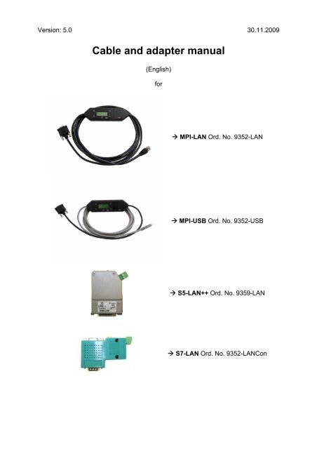
Version: 5.0 30.11.2009<br />
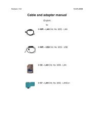
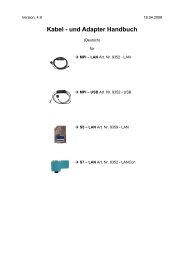
<strong>Cable</strong> <strong>and</strong> <strong>adapter</strong> <strong>manual</strong><br />
(English)<br />
for<br />
� MPI-LAN Ord. No. 9352-LAN<br />
� MPI-USB Ord. No. 9352-USB<br />
� S5-LAN++ Ord. No. 9359-LAN<br />
� S7-LAN Ord. No. 9352-LANCon
Table of content<br />
1. MPI-LAN Ord. No. 9352-LAN............................................................................. 4<br />
1.1. Description................................................................................................ 5<br />
1.2. System requirements................................................................................ 5<br />
1.3. Connection possibilities ............................................................................ 6<br />
1.4. Installation ................................................................................................ 9<br />
1.5. Control elements..................................................................................... 10<br />
1.6. Operating instructions............................................................................. 13<br />
1.6.1. Configure the cable ............................................................................. 13<br />
1.6.1.1. By using the cable operating system ............................................... 13<br />
1.6.2. Using the PLC – VCOM software........................................................ 14<br />
1.6.3. Using a PLC software ......................................................................... 14<br />
1.6.4. Merge two PLCs together by using a network..................................... 37<br />
1.6.5. CP – Mode with ProTool/Pro CS v6.00 ............................................... 41<br />
1.6.6. Option Watchdog ................................................................................ 43<br />
1.7. Menu structure........................................................................................ 46<br />
1.8. Technical data ........................................................................................ 51<br />
2. S7-LAN Ord. No. 9352-LANCon...................................................................... 53<br />
2.1. Description.............................................................................................. 54<br />
2.2. System requirements.............................................................................. 54<br />
2.3. Connection possibilities .......................................................................... 55<br />
2.4. Installation .............................................................................................. 58<br />
2.5. Control elements..................................................................................... 59<br />
2.6. Operating instructions............................................................................. 60<br />
2.6.1. Using the PLC-VCOM software........................................................... 61<br />
2.6.2. Using a PLC software ......................................................................... 62<br />
2.6.3. Direct communication using TCP/IP with Step7© v5.3 (CP mode) ..... 85<br />
2.6.4. Merge two PLCs together by using a network..................................... 97<br />
2.6.5. CP – Mode with ProTool/Pro v6.00 ................................................... 100<br />
2.6.6. Option Watchdog .............................................................................. 102<br />
2.7. Technical data ...................................................................................... 105<br />
3. MPI-LAN / S7-LAN Configuration ................................................................. 106<br />
3.1. By using the Web – Interface................................................................ 106<br />
3.2. Ports ..................................................................................................... 117<br />
4. S5-LAN++ Ord. No. 9359-LAN....................................................................... 118<br />
4.1. Description............................................................................................ 119<br />
4.2. System requirements............................................................................ 119<br />
4.3. Connection possibilities ........................................................................ 120<br />
4.4. Installation ............................................................................................ 123<br />
4.4.1. Installation of the Step5© special driver for S5-LAN++/PG-USB ...... 124<br />
4.5. Control elements................................................................................... 126<br />
4.6. Operating instructions........................................................................... 127<br />
4.6.1. Configure the S5 module .................................................................. 127<br />
4.6.2. Using the PLC-VCOM software......................................................... 128<br />
4.6.3. Using a PLC software ....................................................................... 129<br />
4.6.4. Direct communication with WinCC 6.0 .............................................. 142<br />
4.6.5. S5 – Gateway communication........................................................... 145<br />
4.6.5.1. Specifications of the configuration part.......................................... 147<br />
4.7. Technical data ...................................................................................... 150<br />
4.7.1. Principle Schematics of the S5-LAN++ ............................................. 150<br />
Page 2 <strong>Cable</strong> <strong>and</strong> <strong>adapter</strong> <strong>manual</strong> © by PI 2009
4.7.2. Ports.................................................................................................. 151<br />
5. MPI-USB Ord. No. 9352-USB ........................................................................ 152<br />
5.1. Description............................................................................................ 153<br />
5.2. System requirements............................................................................ 153<br />
5.3. Connection possibilities ........................................................................ 154<br />
5.4. Installation ............................................................................................ 157<br />
5.5. Control elements................................................................................... 158<br />
5.6. Operating instructions........................................................................... 161<br />
5.6.1. Configure the cable ........................................................................... 161<br />
5.6.2. Using the PLC-VCOM software......................................................... 162<br />
5.6.3. Using a PLC software ....................................................................... 162<br />
5.6.4. Configuring the operator panel by using the MPI-USB cable ............ 181<br />
5.7. Menu structure...................................................................................... 181<br />
5.8. Technical data ...................................................................................... 187<br />
6. PLC – VCom................................................................................................... 189<br />
6.1. Description............................................................................................ 189<br />
6.2. Installation ............................................................................................ 189<br />
6.3. Operating instructions........................................................................... 195<br />
6.4. S5 – LAN Manager ............................................................................... 198<br />
6.5. MPI-LAN Manager ................................................................................ 201<br />
7. MPI_DP_PPI Driver........................................................................................ 202<br />
7.1. Description............................................................................................ 202<br />
7.2. Installation ............................................................................................ 202<br />
7.3. Interface Assignment ............................................................................ 205<br />
7.4. Properties ............................................................................................. 206<br />
7.5. extended Properties.............................................................................. 208<br />
7.6. Diagnostics ........................................................................................... 209<br />
7.7. Deinstallation ........................................................................................ 209<br />
8. Troubleshooting ............................................................................................ 211<br />
8.1. Frequently Asked Questions................................................................. 211<br />
© by PI 2009 <strong>Cable</strong> <strong>and</strong> <strong>adapter</strong> <strong>manual</strong> Page 3
1. MPI-LAN Ord. No. 9352-LAN<br />
Page 4 <strong>Cable</strong> <strong>and</strong> <strong>adapter</strong> <strong>manual</strong> © by PI 2009
1.1. Description<br />
The MPI-LAN cable connects the computer with a MPI - or a Profibus - interface<br />
(PLC) by using a TCP/IP network.<br />
1.2. System requirements<br />
Operating systems<br />
- Windows 98 + SE/ME/NT/2000/XP<br />
Software<br />
- PLC – programming software (e.g. PG2000, Step© 7, S7 for Windows,<br />
Microwin)<br />
- PLC - VCom software (see chapter 6)<br />
Hardware<br />
- Network interface card (NIC) 10/100MBit installed in the computer.<br />
The NIC must provide a RJ – 45 interface. Older network interface card types are often<br />
using BNC interfaces.<br />
© by PI 2009 <strong>Cable</strong> <strong>and</strong> <strong>adapter</strong> <strong>manual</strong> Page 5
1.3. Connection possibilities<br />
MPI-LAN directly connected to the computer.<br />
Page 6 <strong>Cable</strong> <strong>and</strong> <strong>adapter</strong> <strong>manual</strong> © by PI 2009
MPI-LAN connected with the computer using a switch or hub.<br />
© by PI 2009 <strong>Cable</strong> <strong>and</strong> <strong>adapter</strong> <strong>manual</strong> Page 7
MPI-LAN Connection possibilities with operator panel<br />
Page 8 <strong>Cable</strong> <strong>and</strong> <strong>adapter</strong> <strong>manual</strong> © by PI 2009
1.4. Installation<br />
Hardware<br />
Connect the MPI-LAN cable (short side) with the MPI interface (9 pins) of the S7 -<br />
PLC. The network connector from the long side of the cable (RJ – 45) should be<br />
connected as described:<br />
MPI-LAN cable to computer:<br />
Connect the network connector from the MPI cable to the network card interface (RJ<br />
– 45) of your computer.<br />
MPI-LAN cable to switch/hub:<br />
Connect the network connector of the MPI cable to the uplink port of your switch/hub.<br />
If you are using an auto - negotiated switch you can put the network connector into a<br />
free port of your choice.<br />
MPI-LAN with a operator panel:<br />
Connect the cable of the operator panel with the PPI/MPI/PROFIBUS – interface of<br />
the PLC. Connect the MPI-LAN cable (short side/9 pin plug) with this interface<br />
(PPI/MPI/PROFIBUS) so that both cables (MPI-LAN <strong>and</strong> Operator Panel) are<br />
plugged into one interface.<br />
Connect the MPI-LAN with the network as described above.<br />
There must be a serial communication with the operator panel if this op is new/used at<br />
the first time. Therefore connect your operator panel with the serial COM interface of<br />
your computer. After the communication has been running successfully the panel is<br />
ready to be connected to the PLC.<br />
The PLC supports the cable with power. The cable provides an alternative power<br />
supply interface which can be connected by a 24V/DC <strong>adapter</strong> (screw clip or a MPI –<br />
net <strong>adapter</strong>). As soon as the cable is supported with power it shows its software<br />
version on the display <strong>and</strong> begins to test its internal components.<br />
Software<br />
To communicate with the PLC, please install the PLC - VCom software, as described<br />
in chapter 6.2.<br />
You also need programming software (e.g. PG 2000, Step© 7, S7 for Windows,<br />
Microwin) to work with the PLC.<br />
© by PI 2009 <strong>Cable</strong> <strong>and</strong> <strong>adapter</strong> <strong>manual</strong> Page 9
1.5. Control elements<br />
a. Keys<br />
b. Default display (Menu Messages)<br />
a. Keys<br />
Key Name Description<br />
� ENTER Change menu <strong>and</strong> confirm input.<br />
� LEFT Go one menu level back. Cancel input (Input will not be saved).<br />
� RIGHT Select sub menu.<br />
� UP Navigate upwards. Increments a value.<br />
� DOWN Navigate downwards. Decrements a value.<br />
Page 10 <strong>Cable</strong> <strong>and</strong> <strong>adapter</strong> <strong>manual</strong> © by PI 2009
. Default display (Menu Messages)<br />
First Line<br />
First Line ►#02PD00▀<br />
Second Line ►!02AG04°<br />
Display description from left to right.<br />
#02 � there are two active stations on the MPI – BUS.<br />
PD � letter definition of the PC - Baud rate.<br />
Display Descriptions<br />
PD 115,2k or baud rate recognition is active.<br />
P? Baud rate recognition <strong>and</strong> access way active.<br />
TD 115,2k or baud rate recognition is active.<br />
(cable is configured as TS – <strong>adapter</strong>)<br />
PG 19,2k<br />
TS 19,2k (cable is configured as TS – <strong>adapter</strong>)<br />
Pg 38,4k<br />
Ts 38,4k (cable is configured as TS – <strong>adapter</strong>)<br />
pG 57,6k<br />
tS 57,6k (cable is configured as TS – <strong>adapter</strong>)<br />
PM PPIMulti (187,5k)<br />
00 � the station number of the MPI – cable. (Default is „0“)<br />
(In the system configuration click on „Set PG/PC interface“. In the<br />
following dialog click „Properties“. Now you can change in the registry card<br />
„MPI“ the „Address“ of the cable.)<br />
(In the PG 2000 software you can find it by clicking on „Options“ �<br />
„Interfaces“. Near the bottom of the dialog you can change the „local address“<br />
of the cable.)<br />
▀ � if this sign appears in the top of the first line, then the cable is communicating<br />
with the PLC. If this sign appears in the bottom of the first line it is<br />
communicating with the computer.<br />
© by PI 2009 <strong>Cable</strong> <strong>and</strong> <strong>adapter</strong> <strong>manual</strong> Page 11
Second Line<br />
! (Exclamation mark) � specifies the connection type to the PLC.<br />
Display Description<br />
! Directly connected to the PLC.<br />
? Not direct connected to the PLC.<br />
! (inverse) Directly connected to the PLC with passive block of the PLC.<br />
? (inverse) Not direct connected to the PLC with passive block of the PLC.<br />
02 � is the station number of a connected <strong>and</strong> active PLC in the MPI - Bus.<br />
Every 750 milliseconds (a ¾ second) another station is displayed, if more than<br />
one has been recognized.<br />
AG � specifies the protocol which is used to communicate with the computer:<br />
Display Description<br />
AG Unknown because there is no connection or an older protocol version<br />
is used.<br />
Ag v5.1 Protocol<br />
ag v5.0 Protocol<br />
04 � Shows the station number of the device, which actual is connected with the<br />
computer software (in this example station number 04).<br />
Configuration specific messages.<br />
The menu message is changing while configuring the following baud rates (see<br />
chapter 1.7 Menu structure for detail):<br />
Baud rate – configuration 1. Line 2. Line<br />
PPI 9,6k – (PPISER96) PPISER96 ACTIVE<br />
PPI 19,2k – (PPISER19) PPISER19 ACTIVE<br />
PPI 187,5k – (PPIMulti) ???PM? ????<br />
PPILAN – (PPILAN) PPILAN ACTIVE<br />
PPIUSB – (PPIUSB) PPIUSB ACTIVE<br />
SONDSER SONDSER 19,2 kBaud 8N1<br />
SONDUSB SONDUSB 38,2 kBaud 7E2<br />
Description 8N1:<br />
8 = Data bits<br />
N = Parity<br />
1 = Stop bit<br />
Page 12 <strong>Cable</strong> <strong>and</strong> <strong>adapter</strong> <strong>manual</strong> © by PI 2009
1.6. Operating instructions<br />
Be sure that your system is supported. If you do not know see chapter 1.2 System<br />
requirements. Also be sure to have connected the cable correctly; otherwise see<br />
chapter 1.3 Connection possibilities <strong>and</strong>/or chapter 1.4 Installation.<br />
1.6.1. Configure the cable<br />
� #01P? °<br />
!02AG °<br />
�<br />
�<br />
�<br />
�<br />
1.6.1.1. By using the cable operating system<br />
° MENU °<br />
°Config°<br />
°Config°<br />
MPI-BUS°<br />
� °MPI/PPI<br />
Baudrate<br />
�<br />
�<br />
�<br />
�<br />
�<br />
MPI-Baud<br />
° Auto °<br />
°Config°<br />
°PG/PC °<br />
� °PG/PC °<br />
Baudrate<br />
�<br />
�<br />
�<br />
�<br />
�<br />
�<br />
�<br />
PG-Baud°<br />
from PC°<br />
°Config°<br />
°IP adr°<br />
°Config°<br />
SNetMask<br />
Take the cable <strong>and</strong> press the Enter – Key �. (Control elements<br />
see chapter 1.6).<br />
Navigate with the Up/Down – Keys �� until you reach the Menu<br />
“Config”. Press Enter �.<br />
Search for the submenu „MPI – BUS“. Enter with �.<br />
Press Enter � to configure the “Baudrate”.<br />
Navigate to the entry “Auto” <strong>and</strong> confirm with �<br />
Press � to return to the “Config” menu. Search for “PG/PC” <strong>and</strong><br />
get in with �.<br />
Press � to get in.<br />
Search for the entry “from PC” <strong>and</strong> press � to set the<br />
configuration.<br />
Go back to the “Config” menu <strong>and</strong> navigate to “IP adr”. In this<br />
menu you should set a valid IP address. To do so navigate with<br />
the �� keys <strong>and</strong> set the values with the �� keys.<br />
Confirm your configuration with �.<br />
Back in the “Konfig“ menu the subnet mask must be set. Therefore<br />
got to the entry “SNetMask“ <strong>and</strong> configure it as described for the<br />
IP address. As soon as you are ready press the enter – key � to<br />
save your configuration.<br />
© by PI 2009 <strong>Cable</strong> <strong>and</strong> <strong>adapter</strong> <strong>manual</strong> Page 13
Now the cable is ready for work. Just get back to the “Message” menu to see the<br />
status.<br />
1.6.2. Using the PLC – VCOM software<br />
1. Start the PLC – VCom application.<br />
2. Press in the section state in the dialog the button „configure“. The assistant starts.<br />
3. Choose the desired MPI cable <strong>and</strong> click „OK“ to go on.<br />
4. If the connection is established the chosen cable is shown in the section state <strong>and</strong><br />
on the left side you can see the status connected.<br />
If you are having problems with using the PLC – VCom dialog, go to chapter 6.3<br />
Operating instructions of the PLC – VCom description.<br />
The virtual COM-Port is only view-, select- <strong>and</strong> accessible when the PLCVCOM<br />
is in the „connected“ state, that means a cable is present <strong>and</strong> usable.<br />
1.6.3. Using a PLC software<br />
a. PG 2000 (v4.41)<br />
b. Set PG/PC interface<br />
c. SIMATIC Step© 7 Manager (v5.2 + SP1)<br />
d. Windows Control Center (WinCC) (v6.0)<br />
e. Windows Control Center flexible 2004 (WinCC flexible) (v5.2.0.0)<br />
f. ProTool/Pro (v6.0 + SP2)<br />
g. Microwin v3.2<br />
h. Microwin v4.0 in the PPI multimaster mode<br />
i. S7 for Windows v5.02<br />
Page 14 <strong>Cable</strong> <strong>and</strong> <strong>adapter</strong> <strong>manual</strong> © by PI 2009
a. PG 2000 (v4.41)<br />
1. Start the PG 2000 software by using the desktop link<br />
or by using the application entry in the start menu.<br />
2. In the menu „Options“ click „Interfaces“.<br />
3. A dialog appears. In the section „Interface“ you can<br />
configure the „PLC – Interface“ (COM – Port).<br />
4. Configure the baud rate in the section „Bus<br />
access“ to „19,2k“. Below change the value for PC<br />
- MPI to „187,5kBaud“.<br />
5. Save your configuration by pressing „OK“.<br />
6. Now the software is ready to establish a<br />
connection to the PLC. cick the symbol „Open“ <strong>and</strong><br />
afterwards press „PLC“. As a alternative action you<br />
can click „File“ � „Open“ � „PLC“.<br />
The connection between PG 2000 <strong>and</strong> the PLC is now established.<br />
A new window appears. Now you can edit the blocks in the PLC.<br />
© by PI 2009 <strong>Cable</strong> <strong>and</strong> <strong>adapter</strong> <strong>manual</strong> Page 15
. Set PG/PC interface<br />
This step is important fort he following software<br />
� SIMATIC Step© 7 Manager (v5.2 + SP1)<br />
� Windows Control Center (WinCC) (v6.0)<br />
� Windows Control Center flexible 2004 (WinCC flexible) v5.2.0.0<br />
� ProTool/Pro (v6.0 + SP2)<br />
� Microwin<br />
If the software you are using is not in the list above you can skip setting up the<br />
PG/PC interface.<br />
1. Open the system configuration by using the start<br />
menu.<br />
2. Click on „Set PG/PC interface“.<br />
3. A Dialog with a list box named „Interface Parameter<br />
Assignment Used:” appears. This box should offer<br />
some „PC - Adapter” <strong>and</strong>/or „TCP/IP” (if you<br />
want to use RFC1006) entries. If you cannot<br />
find these entries go ahead with the steps<br />
PC Adapter or TCP/IP otherwise skip these<br />
steps.<br />
PC - Adapter(Auto, MPI, PROFIBUS)<br />
4. Click on „Choose“ to add these entries to the<br />
PG/PC interface configuration.<br />
5. In this dialog you can deinstall every<br />
installed construction set <strong>and</strong> install the entries in the „Selection“ box. Choose<br />
„PC - Adapter“ from the „Selection“ box on the left side <strong>and</strong> click on „Install“. The<br />
chosen construction set will be<br />
installed <strong>and</strong> a question appears<br />
which asks you to use the<br />
„MPI“ access for the PLC used.<br />
Click „Yes“ if you want to use<br />
the „MPI“ communication type.<br />
Otherwise click „No“ (e.g. if you<br />
want to use the<br />
“PROFIBUS“ communication<br />
type).<br />
Page 16 <strong>Cable</strong> <strong>and</strong> <strong>adapter</strong> <strong>manual</strong> © by PI 2009
TCP/IP RFC1006 Communication<br />
6. Click on „Choose“ to install the elements required by the RFC1006<br />
communication type.<br />
7. „Choose“ „TCP/IP“ <strong>and</strong> click on „Install“. If the installation has been successfully<br />
finished „Close” the dialog.<br />
8. Back in the „Set PG/PC interface“ dialog you will now find the desired entries<br />
called „PC - Adapter(Auto)“ (not supported), „PC - Adapter(MPI)“ <strong>and</strong> „PC -<br />
Adapter(PROFIBUS)“. Now you are able to configure the bus. If you want to use<br />
the „MPI“ communication type go ahead with step b9. Step b12 begins to<br />
describe the „PROFIBUS“ configuration.<br />
MPI configuration<br />
9. A dialog appears. Mark „PC Adapter(MPI)“ Now press „Properties“.<br />
10. In the register card „MPI“ choose the Transmission Rate „187,5 kbit/s“ in the<br />
section „Network Parameters”.<br />
© by PI 2009 <strong>Cable</strong> <strong>and</strong> <strong>adapter</strong> <strong>manual</strong> Page 17
PROFIBUS configuration<br />
11. The register card „Local Connection“ offers<br />
you the possibility to choose the COM –<br />
Port <strong>and</strong> to configure the speed of the MPI<br />
cable. Select the virtual COM – Port<br />
created by the PLC - VCom. Now configure<br />
to the list element „Transmission<br />
rate“19200.<br />
12. Select the entry „PC - Adapter(PROFIBUS)“ <strong>and</strong> click on „Properties“.<br />
13. Set in the registry card „Locale connection“ the<br />
„Connection to:“ parameter to the one simulated<br />
by your PLC - VCom software. (e.g. „COM3“).<br />
Below you can set the „Transmission Rate:“ to<br />
„19200“.<br />
14. Choose the registry card „PROFIBUS“<strong>and</strong> set<br />
the „Transmission Rate:“ to „187,5kbit/s“. Set the<br />
„Profile:“ to „DP“ („Decentral Peripherie“).<br />
15. Save your settings by pressing the „OK“button<br />
<strong>and</strong> close the opened „Set PG/PC -<br />
interface“ dialog.<br />
Page 18 <strong>Cable</strong> <strong>and</strong> <strong>adapter</strong> <strong>manual</strong> © by PI 2009
TCP/IP RFC1006 Configuration<br />
16. For this communcation type just configure the software you want to use.<br />
The interface settings are completed.<br />
Go ahead with the software you want to use.<br />
ProTool/Pro RunTime (RT) Configuration<br />
17. If you want to use the ProTool/Pro RunTime (RT)<br />
applikation you can configure the parameters as<br />
shown by using the entry „DPSONLINE“ in the list<br />
box displayed in the upper part of the dialog of the<br />
„Set PG/PC interface” dialog.<br />
c. SIMATIC Step© 7 Manager (v5.2 + SP1)<br />
Please be sure that the interface configuration is correct as described in point b<br />
1. Start your SIMATIC Step© 7 Manager by using the desktop link or the application<br />
entry in the start menu.<br />
the PLC.<br />
2. Click „PLC“. In the drop - down menu click „Display<br />
Accessible Nodes „.<br />
The connection between the SIMATIC S7 Manager <strong>and</strong><br />
the PLC is now established.<br />
A new window appears. Now you can edit the blocks of<br />
d. Windows Control Center (WinCC) (v6.0)<br />
Please be sure that the interface configuration is correct as described in point b<br />
1. Start WinCC by using the desktop link or the program entry in the start menu.<br />
2. Choose „New” in the menu „File” or click on the white („letter”) symbol to start a<br />
new project.<br />
© by PI 2009 <strong>Cable</strong> <strong>and</strong> <strong>adapter</strong> <strong>manual</strong> Page 19
3. The next dialog offers you several project types<br />
„Single - User Project“, „Multi - User Project“ <strong>and</strong><br />
„Client Project“. The next steps are describing the<br />
„Single - User Project“.<br />
If you are using „Multi - User“ - or „Client“ - Project<br />
please read the WinCC <strong>manual</strong> for detail.<br />
4. “OK“ leads you to a new dialog. Type in the „Project Name“ <strong>and</strong> the „Subfolder“ of<br />
the „Project Path“. With „Create“ the<br />
chosen configuration is confirmed.<br />
6. For a proper working communication<br />
with the PLC there must be defined<br />
how the software has to<br />
communicate with the PLC.<br />
Therefore right click on „Tag<br />
Management“ to open the context<br />
menu. Choose „Add New Driver ...“.<br />
5. Please wait until the project is created.<br />
Afterward the project content is shown<br />
in the left part of the main window.<br />
7. In the „Add new driver“ dialog select the driver which fits to your PLC. For a S7<br />
PLC choose „SIMATIC S7 Protocol Suite.chn“. If you are using a different PLC<br />
please inform yourself which driver fits with your PLC.<br />
It is important that the chosen driver fits with the PLC otherwise the connection cannot<br />
be established.<br />
Page 20 <strong>Cable</strong> <strong>and</strong> <strong>adapter</strong> <strong>manual</strong> © by PI 2009
8. Now you should exp<strong>and</strong> in the „Tag Management“ the branch SIMATIC S7<br />
PROTOCOL SUITE. A lot of protocols for different connection types will appear.<br />
General method for creating a new connection is: Right click on the desired<br />
connection (MPI - > Picture: „MPI“, TCP/IP - > Picture: „TCP/IP“). A context<br />
menu opens. Click on „New Driver Connection…”. This <strong>manual</strong> describes two<br />
connection configurations. MPI (step 9) <strong>and</strong> TCP/IP (step 10 – 17).<br />
Picture: MPI Picture: TCP/IP<br />
MPI<br />
9. Now you are able to type in the name of the<br />
connection. With a click on „Configuration“ a new<br />
dialog will appear. Set up the station address of<br />
the PLC (in this example „2“).<br />
TCP/IP<br />
10. A dialog appears where you can configure the<br />
connection parameters. Set up the IP - Address<br />
of the MPI - LAN cable <strong>and</strong> configure the rack<br />
number as well as the slot number.<br />
Confirm this configuration by pressing<br />
„OK”. (Example configuration: IP -<br />
Address: 192.168.1.55, Rack -<br />
Number: 0, Slot - Nr.: 2)<br />
11. With a right click on the new<br />
connection you can start the<br />
properties dialog. In this dialog<br />
please click on properties.<br />
© by PI 2009 <strong>Cable</strong> <strong>and</strong> <strong>adapter</strong> <strong>manual</strong> Page 21
12. In the properties of the channel unit you<br />
can see all „available connections”.<br />
Choose the newly created one <strong>and</strong> click<br />
again on „Properties”. Now you can see<br />
all the variables which has been<br />
created for this connection. In fact this<br />
connection is a new one so there will be<br />
no variable in the list. To add a new<br />
variable click on „New”.<br />
13. Now set up the name of the variable<br />
(e.g. „S7LAN_MW0”) <strong>and</strong> other<br />
configuration data. Our example has<br />
the following configuration: Name:<br />
„S7LAN_MW0“, Data type: „unsigned<br />
16 - Bit value“, Length: „2“, Address: „MW0“, Format adaptation:<br />
„WordToUnsignedWord“. Click on „Choose” beside the Address to define the<br />
address from the variable. Example configuration: The data area from the variable<br />
is set to „Mark“ <strong>and</strong> the address is set to „Word”. The edit box „MW“ is set to „0”.<br />
14. Confirm all open dialogs with „OK“.<br />
15. The connection needs to know which network interface card it should use to send<br />
data via the Ethernet. Open the „System parameters“ dialog from the context<br />
menu (right click on TCP/IP).<br />
16. Choose the registry card „Unit“ <strong>and</strong> set the „logical device name“ to your network<br />
interface card (usually the name of the NIC begins with a „TCP/IP - > „).<br />
17. Confirm with „OK“.<br />
Now you are able to start the communication. Stop it by pressing<br />
Page 22 <strong>Cable</strong> <strong>and</strong> <strong>adapter</strong> <strong>manual</strong> © by PI 2009
To clean up errors faster the WinCC Software offers a tool named „Channel<br />
Diagnosis”. This tool analyses all connections from your WinCC software. For<br />
demonstration purposes please stop the newly started connection from your WinCC<br />
explorer.<br />
18. Start the software „Channel Diagnosis“ using your link in the start menu.<br />
19. The tool could not detect a running connection so it marked the connection/s with<br />
a red ‘X’ (registry card „Channels/Connections“). Click on the newly created, not<br />
active connection (with the red ‘X’) <strong>and</strong> some information from the connection will<br />
appear in the right part of the dialog. One of these counters is called „Last Error<br />
Code“.<br />
© by PI 2009 <strong>Cable</strong> <strong>and</strong> <strong>adapter</strong> <strong>manual</strong> Page 23
20. Click with the right mouse key on this counter <strong>and</strong> choose „Help” from the context<br />
menu. A yellow window appears (tooltip) with detailed error description.<br />
21. Lets see what happens if the connection runs properly. Start the connection from<br />
your WinCC Explorer. The „Channel Diagnosis“ dialog marks the connection with<br />
a green hook.<br />
Page 24 <strong>Cable</strong> <strong>and</strong> <strong>adapter</strong> <strong>manual</strong> © by PI 2009
e. Windows Control Center flexible 2004 (WinCC flexible) v5.2.0.0<br />
Please be sure that the interface configuration is correct as described in point b<br />
1. Start the WinCC flexible 2004 software by using the desktop link or the program<br />
entry in the start menu.<br />
2. At first click on „Create an empty project“ in the „Start page“.<br />
3. In the „Device selection“mark the<br />
used operator panel (example: „TP<br />
170A“)<strong>and</strong> confirm with „OK“.<br />
4. After the project has been created<br />
right click in the project window on<br />
„Connections“ of the sub menu<br />
„Communication“. In the context<br />
menu click on „Add Connection“.<br />
5. A new configuration window opens in the right part of the main window. Important<br />
for a working connection is:<br />
� the communication driver (set up which PLC you are using (example:<br />
„SIMATIC S7 300/400“))<br />
� the Baud rate (configure the baud rate you have already configured to the<br />
PG/PC interface (e.g. „187500“))<br />
� the address of the terminal (HMI) (in this example „1“)<br />
� the Profile („MPI“ for example)<br />
� the Highest Station Address (HSA) (e.g. „126“)<br />
� the address of the PLC (e.g. „2“)<br />
(see picture on next page)<br />
© by PI 2009 <strong>Cable</strong> <strong>and</strong> <strong>adapter</strong> <strong>manual</strong> Page 25
6. Now you can start with your work. If you have<br />
finished work you can transfer this project to<br />
the panel by reading the next steps.<br />
7. Choose „Transfer Settings“ from the sub<br />
menu „Transfer”.<br />
8. In the new dialog change the „Mode“ to<br />
„MPI/DP“ <strong>and</strong> set the „Station address“ of the<br />
operator panel (e.g. „1“). If desired you can switch the „Delta transfer“ to „On” (in<br />
this example we set it „Off”).<br />
Page 26 <strong>Cable</strong> <strong>and</strong> <strong>adapter</strong> <strong>manual</strong> © by PI 2009
9. Press the button „Transfer“ to start communication with the terminal. Your project<br />
is about to be transferred.<br />
The WinCC flexible software is now able to communicate with your operator panel.<br />
© by PI 2009 <strong>Cable</strong> <strong>and</strong> <strong>adapter</strong> <strong>manual</strong> Page 27
f. ProTool/Pro v6.0 SP2<br />
Please be sure that the interface configuration is correct as described in point b<br />
1. Start ProTool/Pro by using the desktop link or program entry in the start menu.<br />
2. Choose from the menu „File“ the sub menu „New“ or click on the right symbol.<br />
3. The next dialog askes you which<br />
operator panel you are using. Mark the<br />
used panel (e.g. „TP 170A“)<br />
4. „Next“ leads you to a new dialog. Type<br />
in the specfic fields the name of the<br />
PLC device <strong>and</strong> choose the used PLC<br />
in the driver selection (e.g. „SIMATIC<br />
S7 – 300/400 V6.0“).<br />
5. Via „Parameter...“ you are calling an<br />
configuration dialog from the chosen<br />
PLC driver. Set up the station address<br />
of the panel (example „1“) <strong>and</strong> of the PLC<br />
(example „2“). In the sector „Net<br />
parameter“ choose the interface which uses<br />
your cable on the PLC (e.g. „MPI“).<br />
Configure the baud rate to „187.5“.<br />
6. The button „More ...“ leads you to a small<br />
dialog where the „Highest Station<br />
Address“ should be configured to „126“. Set<br />
up the „Number of masters“ (e.g. „1“) <strong>and</strong><br />
confirm with „OK“ until you got back to the „Control Selection“.<br />
7. Go on with „Next“.<br />
9. Confirm with<br />
„OK“ <strong>and</strong><br />
start with<br />
your work. If<br />
you have finished working on this project you can go on<br />
with the next steps.<br />
8. In the main window start the Transfer<br />
Settings dialog by clicking on „File“ �<br />
„Transfer“ � „Settings...“. Choose „MPI<br />
/ PROFIBUS DP“ from the listbox <strong>and</strong><br />
type in the station address of the<br />
operator panel (e.g. „1“).<br />
Page 28 <strong>Cable</strong> <strong>and</strong> <strong>adapter</strong> <strong>manual</strong> © by PI 2009
10. If you want to transfer you project to the panel you have to generate<br />
the project first. This can be done with a click on „File“ � „Compile“.<br />
11. To transfer the project just click on „File“ � „Download“ „Start<br />
Project Download“ or click on the right symbol .<br />
12. Please wait while the project is transferred.<br />
The communication between the operator panel is now<br />
established.<br />
© by PI 2009 <strong>Cable</strong> <strong>and</strong> <strong>adapter</strong> <strong>manual</strong> Page 29
g. Microwin v3.2 (only for S7 200)<br />
Please be sure that the interface configuration is correct as described in point b<br />
1. Start the Microwin software by using the desktop link or the<br />
program entry in the start menu.<br />
2. Click on „Type“ in the menu „PLC”. Configure the „PLC<br />
Type“ (e.g. „CPU 224“) as well as the „CPU Version“ (e.g.<br />
„01.22”) to the dialog.<br />
3. Click on „Communications...” to start the next dialog. In the sector „Address” set<br />
up the „Remote” listbox with the station address of the PLC (e.g. „2”).<br />
Page 30 <strong>Cable</strong> <strong>and</strong> <strong>adapter</strong> <strong>manual</strong> © by PI 2009
If you skipped the point b („Set up PG/PC interface“) you can configure the PG/PC<br />
interface with a click on „Set PG/PC interface“.<br />
4. In the right part of the dialog double click on the blue arrow symbol to test the<br />
communication with the PLC.<br />
5. The sector „Address“ should be updated <strong>and</strong> displays the „PLC Type”. Also the<br />
CPU of the PLC is displayed in the right part of the dialog.<br />
6. Confirm with „OK“ until you get back to the main window.<br />
The communication with the PLC ist now established.<br />
© by PI 2009 <strong>Cable</strong> <strong>and</strong> <strong>adapter</strong> <strong>manual</strong> Page 31
h. Microwin v4.0 using the PPI Multimaster mode<br />
Please be sure that the interface configuration is correct as described<br />
in point b<br />
The PPI Multimaster mode has been developed for the purpose that multiple devices<br />
can communicate parallel with one PLC. The following steps describe how to<br />
configure this mode.<br />
1. The cable must be set to PPIMulti mode. Therefore go to the „Config” menu.<br />
2. Set it to „PPIMulti“ with the cursors of the cables case <strong>and</strong> press return to confirm<br />
this configuration. The menu „Messages” (first menu) displays now „PM“ in the<br />
first line.<br />
3. Now you have to set the PG/PC interface. You can do this by using the Microwin<br />
software. Start the Microwin software.<br />
4. Click on „Set PG/PC Interface“ at the left side of the applikation window. See the<br />
picture on the right for further details.<br />
5. Choose the entry „PC/PPI cable(PPI)“ <strong>and</strong> click on „Properties”.<br />
6. In the registry path „PPI“ you can for example the „HSA“.<br />
Page 32 <strong>Cable</strong> <strong>and</strong> <strong>adapter</strong> <strong>manual</strong> © by PI 2009
7. In the registry path „Local Device“set the COM Port („Connection to”) to the one<br />
provided by the PLC VCom software.<br />
8. Confirm your settings with „OK“ <strong>and</strong> click on „Communications” above the „Set<br />
PG/PC Interface” Button you have used before.<br />
© by PI 2009 <strong>Cable</strong> <strong>and</strong> <strong>adapter</strong> <strong>manual</strong> Page 33
9. Click on „Double click to Refresh „. Now the software is searching for the PLC.<br />
10. If the PLC could be found the dialog changes as shown in the picture below:<br />
Page 34 <strong>Cable</strong> <strong>and</strong> <strong>adapter</strong> <strong>manual</strong> © by PI 2009
i. S7 for Windows v5.02<br />
Please be sure that the interface configuration is correct as described in point b<br />
1. Start the „S7 for Windows” software by using the link on your<br />
desktop or use the link in your start menu (st<strong>and</strong>ard is<br />
„Programs\S7 for Windows\S7 for Windows“)<br />
2. Choose File - >Preferences... to configure the communication<br />
configuration between the computer <strong>and</strong> the PLC.<br />
3. A new dialog appears which provides to set up a lot of<br />
configuration data about the communication with your PLC.<br />
4. Choose the first registry card „Interface“ (st<strong>and</strong>ard) <strong>and</strong> set up the configuration<br />
data as descriped below:<br />
� Area: „Preferences from:“ � PC<br />
� Area: „PLC Type:“ � S7<br />
� Area: „Protocol:“ � MPI - Umsetzer<br />
� Area: „Serial Port:“ � Choose the virtual COM port which has been<br />
created by PLC - VCom (e.g. „COM 4”).<br />
� Area: „Baud Rate“ � Choose the speed you want to use at the bus (e.g.<br />
„115200“)<br />
� Area: „MPI Converter:“<br />
o Activate the checkbox „Only Master at the Bus“ if you have only one<br />
PLC in the bus.<br />
o Leave the fields „ S7W MPI Address“ <strong>and</strong> „MPI Address PLC“ as it is.<br />
o The number in the listbox „Max MPI Address“ must be higher than the<br />
PLC with the highest station address in your MPI bus. Otherwise every<br />
PLC which is higher than this number will not been seen (e.g. if there is<br />
only one PLC in your bus „15“ is more than enough).<br />
© by PI 2009 <strong>Cable</strong> <strong>and</strong> <strong>adapter</strong> <strong>manual</strong> Page 35
5. After the software is configured <strong>and</strong> the PLC - VCom is<br />
connected with the PLC, please click „Select PLC” in the<br />
area „MPI Converter“. A new dialog appears where you<br />
can select the desired PLC. While this dialog opens you<br />
can see right now (in the bottom right of the task bar) the<br />
green blinking PLC VCom icon . This means that the<br />
software is already talking to the PLC.<br />
6. The dialog displays all the PLCs that can be found in your MPI bus. Select the<br />
desired one <strong>and</strong> confirm with „OK”.<br />
7. Close the preferences dialog by pressing the „OK“ button.<br />
8. Back in the main window press the „PC Block List“ button for<br />
testing the new established communication configuration.<br />
9. Please wait a moment for the software to read the desired blocks<br />
from the PLC. The blocks will be displayed in the listbox below<br />
the menu bar (see picture to the right).<br />
The communication between the software <strong>and</strong> your PLC is<br />
established.<br />
If you had any trouble up to this point go ahead in chapter 8.1<br />
Frequently Asked Questions.<br />
Page 36 <strong>Cable</strong> <strong>and</strong> <strong>adapter</strong> <strong>manual</strong> © by PI 2009
1.6.4. Merge two PLCs together by using a network<br />
By merging two PLCs together you will be able to transfer data from one PLC to<br />
another. Merging PLCs together is only possible with two S5/S7 PLCs or one S5 PLC<br />
connected with a S7 PLC.<br />
Each MPI-LAN cable can establish up to 8 connections. A S5 - Gateway up to 2.<br />
For this example we have merged a S7 with a S5 PLC.<br />
As an interface between S7 <strong>and</strong> S5 the MPI-LAN cable <strong>and</strong> the S5 – Gateway<br />
module have been used.<br />
MPI-LAN Configuration<br />
The MPI-LAN cable can be configured by using the Web interface (see chapter 3.1)<br />
or by using the keys on the device.<br />
Menu Call the main menu by pressing � in the start screen.<br />
Message<br />
Menu By pressing the cursor key � or � you can select the submenu<br />
Config “Config” <strong>and</strong> get in with �.<br />
Config Select the menu “S7onS7S5” by using the keys � or � <strong>and</strong> confirm<br />
S7onS7S5<br />
Connect.<br />
00<br />
with �<br />
Set the desired connection (0 … 7) (��) <strong>and</strong> confirm with �. The<br />
connection number will always be displayed in the right top corner.<br />
(Except by setting the IP address because it uses too much space).<br />
Now you have got a few more configurations to do.<br />
Configuration/<br />
Submenu<br />
Description<br />
Type Connection type<br />
CPU No Locale Partner station<br />
DB No Communication data block<br />
DW No Start of the communication range in the given communication data<br />
block.<br />
IP Addr Set up the IP address of the partner.<br />
TSAP TSAP<br />
Polltime Poll time<br />
Type<br />
First Line: Type 00<br />
Second Line:<br />
Type Description<br />
OFF Connection is not used.<br />
DBActive (*1) Establishes the connection by using the TCP protocol.<br />
DBPassiv (*1) Waits until another device establishes the connection.<br />
S7Active (*2) Establishes the connection by using the TCP protocol.<br />
S7Passiv (*2) Waits until another device establishes the connection.<br />
(*1) DB Active <strong>and</strong> Passive are using the function blocks FC 55 (send) <strong>and</strong> FC 56 (receive) for data<br />
exchange.<br />
(*2) S7 Active <strong>and</strong> Passive are using a special bridge function for the data exchange.<br />
© by PI 2009 <strong>Cable</strong> <strong>and</strong> <strong>adapter</strong> <strong>manual</strong> Page 37
CPU No<br />
First Line: CPU 00<br />
Second Line: 24<br />
Enter the station number of the PLC which is used for the data exchange.<br />
DB No<br />
First Line: DBNo 00<br />
Second Line: 000010<br />
Enter the number of the data block which is used for the communication.<br />
DW No<br />
First Line: DWNo 00<br />
Second Line: 000010<br />
Enter the starting data byte of the desired data block.<br />
IP Addr<br />
First Line: 1
Data exchanging with the help of the data blocks<br />
� Structure of the communication data block<br />
Data bytes Access type Description<br />
00 – 09 Read Receive area. At this place the data received over the<br />
network will be saved.<br />
10 – 19 Write Send area. At this place the data will be send over the<br />
network.<br />
20 – 30 Read, Write Length, status <strong>and</strong> control byte for the send or receive<br />
area.<br />
HINT: TXLen defines the real length of data which will be send. RXLen contains the number of bytes<br />
received.<br />
� Format of TXERRRDY <strong>and</strong> RXERRRDY<br />
These bytes are containing the transfer status.<br />
Bit Status Description<br />
0 1 Start of the transfer (TXERRRDY).<br />
Receiving allowed (RXERRRDY).<br />
1 1 An error occurred.<br />
2 1 Transfer completed (TXERRRDY).<br />
Received data (RXERRRDY).<br />
3 – 7 ? Reserved<br />
� Usable data types<br />
The following values are possible with the data types TX.TYP <strong>and</strong> RX.TYP.<br />
Values Type Responsible data types<br />
‚D’, ‚d’<br />
Data block TX.DBNR, RX.DBNR<br />
Byte of the data block TX.DWNR, RX.DWNR<br />
‚E’, ‚e’, ‚I’, ‚i’ Reception byte TX.DWNR, RX.DWNR<br />
‚A’, ‚a’, ‚Q’, ‚q’ Output byte TX.DWNR, RX.DWNR<br />
© by PI 2009 <strong>Cable</strong> <strong>and</strong> <strong>adapter</strong> <strong>manual</strong> Page 39
‚M’, ‚m’, ‚F’, ‚f’ Keeping byte TX.DWNR, RX.DWNR<br />
‚T’, ‚t’ Timer TX.DWNR, RX.DWNR<br />
‚Z’, ‚z’, ‚C’, ‚c’ Counter TX.DWNR, RX.DWNR<br />
� Status values (TXSTATUS, RXSTATUS)<br />
Status values Description<br />
0000h Instruction completed<br />
7000h Instruction will not be processed.<br />
80B0h Construction component does not know the record.<br />
80B1h Wrong length in the parameter.<br />
80C3h Memory temporary used.<br />
80C4h Communication error.<br />
8183h Project planning’s not available or service has not been started yet.<br />
8184h Data type or source data range is wrong.<br />
8185h Length exceeds the maximum size of the source data range or the<br />
destination data range is too small.<br />
� Function blocks<br />
o FC 55 (S7LAN_SEND)<br />
o FC 56 (S7LAN_RECV)<br />
These function blocks are used to send <strong>and</strong> receive data.<br />
Page 40 <strong>Cable</strong> <strong>and</strong> <strong>adapter</strong> <strong>manual</strong> © by PI 2009
1.6.5. CP – Mode with ProTool/Pro CS v6.00<br />
Used Software: ProTool/Pro CS v6.00 SP2<br />
1. Creating a new project<br />
Start the ProTool/Pro CS software <strong>and</strong> click on File � New. (for more Information<br />
about creating projects with ProTool/Pro CS v6.00 read the <strong>manual</strong> of the developer).<br />
2. Choosing a destination device<br />
The destination device must support the Ethernet interface.<br />
3. Choosing a PLC<br />
Enter a typical PLC Name <strong>and</strong> select the used PLC type (e.g. „SIMATIC S7 300/400<br />
V6.0“). After choosing the PLC type click on parameter.<br />
OP parameter<br />
Interface If the desired destination device supports “Ethernet” you<br />
can change the interface to “Ethernet”.<br />
Protocol Communication is established by using the IP protocol.<br />
Address Enter the IP address of your computer.<br />
Subnet mask Enter the subnet mask of your computer.<br />
Routing Activate this check box to reach members outside your<br />
subnet. Requires that the construction components of<br />
© by PI 2009 <strong>Cable</strong> <strong>and</strong> <strong>adapter</strong> <strong>manual</strong> Page 41
the station supports routing (CPUs und CPs). More<br />
information you will get in the "STEP 7 Online Help".<br />
Parameter of the partner<br />
Address Enter the IP Address of the MPI-LAN cable which is<br />
plugged onto the PLC.<br />
Slot Enter the slot number of the destination CPU.<br />
Construction<br />
Enter the construction components.<br />
components<br />
Cyclic operation If this check box is active the PLC optimizes the<br />
operation between ProTool/Pro Runtime <strong>and</strong> the PLC.<br />
This is used to get a better performance. For Parallel<br />
operations of more than one computers the cyclic<br />
operation check box should be deactivated.<br />
Confirm the configuration with “OK“.<br />
4. Complete the project<br />
Click on “Next“ <strong>and</strong> then on “Complete“ to end the project start configuration.<br />
5. Alternative configuration<br />
If you select the group “Controls“ in the left part of the window you can see the<br />
available PLCs in the right part. Right click with the mouse button on the PLC <strong>and</strong><br />
select “Properties” in order to get back to the configuration dialog we used in the<br />
project configuration at the beginning.<br />
At least to get there you have to click<br />
on “Parameter“.<br />
6. Transfer properties<br />
In the file menu click on „Transfer“ �<br />
„Properties…“ <strong>and</strong> the following dialog<br />
appears.<br />
Choose “Ethernet“ so that the<br />
connection can be established in the<br />
CP mode.<br />
If “Ethernet“ is activated you can enter<br />
the “IP address“ of the destination<br />
device (MPI-LAN). Confirm with<br />
“OK“ to complete the configuration.<br />
7. Configuration is complete<br />
Now you can transfer the project.<br />
Page 42 <strong>Cable</strong> <strong>and</strong> <strong>adapter</strong> <strong>manual</strong> © by PI 2009
1.6.6. Option Watchdog<br />
With this Option (you must buy it to use it) you could continueosly check the<br />
MPI/Profibus. The Number of detected Parity errors <strong>and</strong> Spikes are counted <strong>and</strong><br />
saved into a 8 Bit Register. This Register could then be read from the PC or<br />
displayed by a WebBrowser. Try to use the special WebSide „WD.HTM“, the<br />
following Output is displayed.<br />
This side will refresh every second after completely loaded. The Counters are always<br />
reset to 0 when read.<br />
You could also access the S7/MPI-LAN directly. Start in a Comm<strong>and</strong>-Shell<br />
„telnet 192.168.1.56 133“ <strong>and</strong> Press . Telnet will establish a connection to<br />
the S7/MPI-LAN with the IP-Address 192.168.1.55 <strong>and</strong> on Port 133 (Statistic Service),<br />
a blank screen is displayed:<br />
© by PI 2009 <strong>Cable</strong> <strong>and</strong> <strong>adapter</strong> <strong>manual</strong> Page 43
The S7/MPI-LAN sends only data when something is recieved on the open TCP/IP<br />
Socket on Port 133 (regardless of the length).<br />
Press now the -Key several times, then the S7/MPI-LAN will response with<br />
some data:<br />
The Structure of the recieved data is descriped in the next table::<br />
Data Description<br />
30h<br />
30h<br />
31h<br />
00h<br />
32h<br />
35h<br />
35h<br />
00h<br />
Parity – Counter as ASCII-Text, including leading Zeros <strong>and</strong> ending ‚\0’<br />
here „001“<br />
Spike - Counter as ASCII-Text, including leading Zeros <strong>and</strong> ending ‚\0’<br />
here „255“<br />
01h Binary Parity – Counter (8 Bit)<br />
FFh Binary Spike - Counter (8 Bit)<br />
On the MEGA-ToolBox CD is also a console-application including source which<br />
shows an example of access to S7/MPI-LAN.<br />
// WDTest.cpp : Definiert den Einsprungpunkt für die Konsolenanwendung.<br />
//<br />
#include "stdafx.h"<br />
typedef struct {<br />
unsigned char ucASCIIParity[4]; // Anzahl Paritätsfehler seit letzter Abfrage<br />
// 3 Ziffern mit abschließender '\0'<br />
unsigned char ucASCIISpikes[4]; // Anzahl erkannter Spikes seit letzter Abfrage<br />
// 3 Ziffern mit abschließender '\0',<br />
unsigned char ucBINParity; // Binärwert der Anzahl Paritätsfehler<br />
unsigned char ucBINSpikes; // Binärwert der Anzahl Spikes<br />
} S7LANINFO;<br />
Page 44 <strong>Cable</strong> <strong>and</strong> <strong>adapter</strong> <strong>manual</strong> © by PI 2009
int main(int argc, char* argv[])<br />
{<br />
SOCKET sS7LAN;<br />
DWORD dwTimeout = 1000L; // 1 Sekunde Timeout<br />
int NaggleOn = 1;<br />
struct sockaddr_in sS7LANAdr;<br />
struct linger sLinger;<br />
S7LANINFO sInfo;<br />
WSADATA sWSAData;<br />
printf("S7LAN Watchdog Test V1.00\n\n");<br />
memset(&sInfo,0,sizeof(sInfo));<br />
if (WSAStartup(MAKEWORD(1,1),&sWSAData) != 0) {<br />
printf("WSA Startup fehlerhjaft => Abbruch\n");<br />
return(0);<br />
}<br />
sS7LAN = socket(AF_INET, SOCK_STREAM, 0); //0<br />
if (sS7LAN != INVALID_SOCKET) {<br />
// Sende/Empfangstimeout einstellen<br />
setsockopt( sS7LAN, SOL_SOCKET, SO_SNDTIMEO,(char *)&dwTimeout, sizeof(dwTimeout));<br />
setsockopt( sS7LAN, SOL_SOCKET, SO_RCVTIMEO,(char *)&dwTimeout, sizeof(dwTimeout));<br />
// Naggle-Algorithmus aus<br />
setsockopt(sS7LAN, IPPROTO_TCP, TCP_NODELAY,(char*) &NaggleOn, sizeof(NaggleOn));<br />
sS7LANAdr.sin_family = AF_INET;<br />
sS7LANAdr.sin_port = htons(133); // Port 133; Statistic Service<br />
sS7LANAdr.sin_addr.S_un.S_un_b.s_b1 = 192; // IP-Adresse des S7LAN's<br />
sS7LANAdr.sin_addr.S_un.S_un_b.s_b2 = 168;<br />
sS7LANAdr.sin_addr.S_un.S_un_b.s_b3 = 1;<br />
sS7LANAdr.sin_addr.S_un.S_un_b.s_b4 = 56;<br />
if (connect(sS7LAN, (struct sockaddr *)&sS7LANAdr, sizeof(sS7LANAdr)) != SOCKET_ERROR) {<br />
// etwas senden => daraufhin ende S7LAN antwort<br />
send(sS7LAN, (const char *) "A", 1, 0);<br />
// Daten vom S7LAN empfangen<br />
if (recv(sS7LAN, (char *)&sInfo, sizeof(sInfo), 0)) {<br />
printf("Parity: %s Spikes: %s\nParity: %3d Spikes:<br />
%3d\n",&sInfo.ucASCIIParity[0],&sInfo.ucASCIISpikes[0],(unsigned int)<br />
sInfo.ucBINParity,(unsigned int) sInfo.ucBINSpikes );<br />
} else {<br />
printf("Empfang vom S7LAN gestört\n");<br />
}<br />
}<br />
sLinger.l_linger = 0;<br />
sLinger.l_onoff = 1; // unmittelbar schlieîen<br />
shutdown(sS7LAN,2); // Read <strong>and</strong> Write<br />
setsockopt(sS7LAN, SOL_SOCKET, SO_LINGER, (char *)&sLinger, sizeof(sLinger));<br />
closesocket(sS7LAN);<br />
} else {<br />
printf("S7LAN nicht ereichbar\n");<br />
}<br />
} else {<br />
printf("Socket nicht öffenbar\n");<br />
}<br />
return 0;<br />
© by PI 2009 <strong>Cable</strong> <strong>and</strong> <strong>adapter</strong> <strong>manual</strong> Page 45
1.7. Menu structure<br />
a. Graphical Description<br />
b. Info<br />
c. Bus<br />
d. Config<br />
The menu messages are described in the previous chapter 1.6 Operating instructions.<br />
Also it is recommended that you are involved in using the MPI cable. See chapter 1.6<br />
Control Elements for being involved.<br />
a. Graphical Description<br />
With � you will get in the menu of the cable. This menu has the following structure.<br />
° MENU °<br />
Message°<br />
St<strong>and</strong>ard display<br />
(Status)<br />
� ° MENU °<br />
°Config°<br />
� ° MENU °<br />
° Bus °<br />
Configuration BUS display<br />
� °Config°<br />
° Mode °<br />
� ° Bus °<br />
Address°<br />
� ° MENU °<br />
° Info °<br />
<strong>Cable</strong> information<br />
� ° Info °<br />
Version°<br />
<strong>Cable</strong> mode Bus address OS Version<br />
� °Config°<br />
Password<br />
Configuration<br />
password<br />
� °Config°<br />
°Reset °<br />
<strong>Cable</strong> reset<br />
� °Config°<br />
Set Def.<br />
Sets the<br />
configuration to<br />
default<br />
� °Config°<br />
Language<br />
Language<br />
� °Config°<br />
S7toS5S7<br />
Configuration for<br />
the data exchange<br />
of two PLCs<br />
� °Config°<br />
Protocol<br />
Protocol which is<br />
used on the bus<br />
� °Config°<br />
°PG/PC °<br />
PG interface<br />
settings<br />
Page 46 <strong>Cable</strong> <strong>and</strong> <strong>adapter</strong> <strong>manual</strong> © by PI 2009
� °Config°<br />
MPI-BUS°<br />
MPI interface<br />
settings<br />
� °Config°<br />
°IP adr°<br />
IP address of the<br />
cable<br />
� °Config°<br />
SNetMask<br />
Subnetmask of the<br />
cable<br />
� °Config°<br />
Gateway°<br />
Gateway<br />
� °Config°<br />
°DHCP °<br />
De-/Activates the<br />
DHCP client<br />
� °Config°<br />
°Data °<br />
Un-/locks<br />
configuration send<br />
by the computer.<br />
b. Info<br />
Select the menu “Info“ to choose, by pressing the Enter – Key �, the sub menu<br />
“Version“. This menu shows you the operating system version of the cable.<br />
c. Bus<br />
Select the menu “Bus“ to choose, by pressing the Enter – Key �, the sub menu<br />
“Address “. With the Up/Down – Keys �� you can find the connected stations.<br />
The menu “Address “:<br />
° Bus °<br />
Address°<br />
The letters in the second line are describing the station:<br />
Letter Description<br />
D The MPI cable is directly connected to<br />
the PLC.<br />
A This station is active in the bus.<br />
P This station is passive in the bus, for e.g.<br />
some OP’s, FM – blocks also MPI Bus –<br />
Slaves.<br />
The numbers are the address of the station.<br />
© by PI 2009 <strong>Cable</strong> <strong>and</strong> <strong>adapter</strong> <strong>manual</strong> Page 47
d. Config<br />
o Mode<br />
o Password<br />
o Reset<br />
o Set Def.<br />
o Language<br />
o S7toS5S7<br />
o Protocol<br />
o PG/PC<br />
o MPI – BUS<br />
o IP Adr<br />
o SNetMask<br />
o Gateway<br />
o DHCP<br />
o Data<br />
• Mode<br />
Choose this menu to change the cables way of working.<br />
Available selections: “MPI-LAN“ – Normal MPI-LAN mode<br />
“PPIMulti“ – S7 200 Multimaster mode<br />
“PPILAN19“ – S7 200 PPI 19.2KBaud<br />
“SOND_LAN“ - Special LAN baud rate<br />
“SOND_SER“ – Special Serial baud rate<br />
“PPILAN96“ – S7 200 PPI 9.6KBaud<br />
• Password<br />
Choose this menu to change the password of the cable – configuration.<br />
(Default: “0“).<br />
• Reset<br />
Press � to perform a system reset.<br />
• Set Def.<br />
Press the Enter – Key � to load the default configuration.<br />
• Language<br />
In this sub menu you can choose your desired language.<br />
Available selections “German“ und “English“.<br />
• S7toS5S7<br />
This menu is to configure connections to other PLCs. To get more information read<br />
chapter 1.6.2.<br />
Page 48 <strong>Cable</strong> <strong>and</strong> <strong>adapter</strong> <strong>manual</strong> © by PI 2009
• Protocol<br />
Change the protocol version. Choose “Auto“ if you want that the cable takes the<br />
configuration from the PG. If you experience any trouble on the bus change the<br />
protocol to “V5.0 Old”. Because this is version is more stable (but slower) than the”V<br />
5.1” protocol.<br />
• PG/PC<br />
In this menu you can change the connection speed between the programming device<br />
<strong>and</strong> the computer. This works only by using a MPI – II (Ord. No. 9352) cable with the<br />
serial plug connected to the computer.<br />
Available baud rates: “2400“, “4800“, “9.6k“, “19.2k“, “38.4k“, “57.6k“, “115.2k“.<br />
If you are using “from PC“ the cable takes the PG configuration.<br />
• MPI – BUS<br />
You have to choose between these sub menus.<br />
- Baudrate<br />
- Master<br />
- local No<br />
- HSA<br />
- Profile<br />
- CP-Mode<br />
- Baudrate<br />
Change the speed of the MPI/Profibus - Bus.<br />
Available baud rates: “Auto“, “19,2k“, “45,45k“, “93,75k“, “187,5k“,<br />
“500k“, “1,5M“, “3M“, “6M“, “12M“.<br />
HINT: The baud rates “3M“, “6M“ <strong>and</strong> “12M“ can only be configured by cable. These higher baud rates<br />
(from “3M” to “12M”) will be overwritten by the PC. To get sure that this will not happen configure (in<br />
the cables menu) “Lock” in the sub menu “Data”. (This sub menu is also described at the bottom of the<br />
next page)<br />
- Master<br />
In the case that the cable is connected with only one passive station, configure<br />
“Master” to the cable to determine that the cable is configuring itself. In all other<br />
cases please configure “Multimaster“ to the cable.<br />
- local No<br />
Changes the station number of the cable. Hexadecimal values of “00“ to “7E“ are<br />
available.<br />
© by PI 2009 <strong>Cable</strong> <strong>and</strong> <strong>adapter</strong> <strong>manual</strong> Page 49
- HSA<br />
HSA st<strong>and</strong>s for Highest Station Address. Configure the highest station number to the<br />
cable which is connected to the MPI bus. Possible values: “from PC“, “15“, “31“, “63“,<br />
“126“.<br />
If you are using “from PC“ the cable takes the PG configuration.<br />
- Profile<br />
Select “St<strong>and</strong>ard“ to use the st<strong>and</strong>ard PROFIBUS mode. “DP“ (Decentral Peripherie),<br />
“DP/FMS“ (Field Message System) <strong>and</strong> “MPI“ (Multi Point Interface) are deviations of<br />
the PROFIBUS st<strong>and</strong>ard.<br />
- CP-Mode<br />
Sets the CP mode configuration. Sets the following options:<br />
Keep in mind that alle except the StatNo will be set automatically while<br />
communicating.<br />
Option Description<br />
StatNo PLC number.<br />
SlotNo Automatic. Slot number of the PLC.<br />
Function Automatic. Enter the correct communication.<br />
0 = Not defined.<br />
1 = Operating terminal communication.<br />
2 = PG communication.<br />
3 = Step7 basis communication.<br />
• IP Adr<br />
Changes the IP address of the cable. With the cursor > < you can move from<br />
number to number. At least there are 4 x 3 numbers to change for a valid IP Address.<br />
• SNetMask<br />
Changes the Subnet Mask of the cable. Like IP Adr.<br />
• Gateway<br />
Changes the Gateway of the cable. Like IP Adr.<br />
• DHCP<br />
Switches the DHCP Client “ON” or “OFF”.<br />
• Data<br />
Change to “Lock“ if you want that configuration data coming of the computer will be<br />
ignored (only important if you are using 1.5MBit or higher baud rates).<br />
The maximum baud rate of the PC driver is used if you “Unlock” this option.<br />
Page 50 <strong>Cable</strong> <strong>and</strong> <strong>adapter</strong> <strong>manual</strong> © by PI 2009
1.8. Technical data<br />
Type Technical Data<br />
Dimensions without<br />
cables<br />
146x41x29mm (LxBxH)<br />
Case type ABS, V0<br />
<strong>Cable</strong> type UL2464, 28AWG, double shielded<br />
Interfaces to the<br />
MPI – BUS<br />
Profibus<br />
PPI<br />
RS485 (19,2/93,5/187,5/500kBaud -<br />
1,5/3/6/12MBaud)<br />
RS485 (9,6/19,2/45,45/93,75/187,5/500KBaud –<br />
1,5/3/6/12MBaud)<br />
RS485 (9,6/19,2/187,5kBaud)<br />
PC/Network<br />
RJ – 45 (10/100MBit)<br />
Supply Voltage DC + 24V/DC ±20%<br />
The 24V/DC will be taken out of the connected PLC or by<br />
external power supply.<br />
Power reception Type I = 100mA by 24V/DC<br />
(5V/DC input are not used)<br />
Output current 5V/DC This 5V/DC output does not drive any load <strong>and</strong> has a<br />
100R resistor in his series. Use it only as bus termination.<br />
Type of protection IP20<br />
Galv. decoupling The internal electronic (<strong>and</strong> RS232) to the bus driver <strong>and</strong><br />
also to the 24V/DC input are decoupled. The shield of the<br />
MPI/PPI side to the RS232 side is connected through.<br />
Order Description: MPI-LAN <strong>Cable</strong> 3m Ord. No. 9352-LAN<br />
Pinning (MPI) PLC<br />
Pin.<br />
No.<br />
Short form Description Direction (cable – view)<br />
1 NC Not connected<br />
2 M24V Ground 24V/DC Input<br />
3 Ltg_B Data line B Input <strong>and</strong> output<br />
4 RTS - AS Ready to send of AS Input<br />
5 M5V Ground 5V/DC Input<br />
6 P5V 5V/DC Output Output<br />
7 P24V 24V/DC Input Input<br />
8 Ltg_A Data line A Input <strong>and</strong> Output<br />
9 RTS - PG Ready to send of AS Output<br />
Shield At both SUB – D cases<br />
© by PI 2009 <strong>Cable</strong> <strong>and</strong> <strong>adapter</strong> <strong>manual</strong> Page 51
Note:<br />
The SUB – D plugs are shielded. The RTS - AS <strong>and</strong> the M5V must lie on this shield<br />
to detect stations. P5V is a output of the cable <strong>and</strong> is needed for bus terminating<br />
reasons. These 5V/DC are usable <strong>and</strong> secured with a 100R resistor.<br />
Important:<br />
Do not lengthen this side. This side leads both 24V/DC <strong>and</strong> 5V/DC. This would<br />
decrease the quality of the signal on the bus.<br />
To lengthen the MPI - LAN cable, please supply the cable externally with 24V/DC<br />
power, <strong>and</strong> lengthen only signals Ltg_A <strong>and</strong> Ltg_B 1:1. Be sure to put the shield on<br />
the SUB – D plug. Also be sure to use terminating resistors where applicable (at the<br />
bus ends).<br />
Page 52 <strong>Cable</strong> <strong>and</strong> <strong>adapter</strong> <strong>manual</strong> © by PI 2009
2. S7-LAN Ord. No. 9352-LANCon<br />
© by PI 2009 <strong>Cable</strong> <strong>and</strong> <strong>adapter</strong> <strong>manual</strong> Page 53
2.1. Description<br />
The S7-LAN module easily connects the PC with a MPI or Profibus interface by using<br />
a TCP/IP – Network.<br />
2.2. System requirements<br />
Operating Systems<br />
- Windows 98 + SE/ME/NT/2000/XP<br />
Software<br />
- SPS – programming software (e.g. PG2000, Step© 7, S7 for Windows,<br />
Microwin)<br />
- PLC - VCom software (see chapter 6)<br />
Hardware<br />
- Network Interface Card (NIC) 10/100MBit<br />
The NIC must provide a RJ – 45 interface. Older network interface card types are<br />
often using BNC interfaces.<br />
Page 54 <strong>Cable</strong> <strong>and</strong> <strong>adapter</strong> <strong>manual</strong> © by PI 2009
2.3. Connection possibilities<br />
S7-LAN directly connected with the PC.<br />
© by PI 2009 <strong>Cable</strong> <strong>and</strong> <strong>adapter</strong> <strong>manual</strong> Page 55
S7-LAN connected to the PC by using a switch or hub.<br />
Page 56 <strong>Cable</strong> <strong>and</strong> <strong>adapter</strong> <strong>manual</strong> © by PI 2009
S7 - LAN connection possibilities with a operator panel<br />
© by PI 2009 <strong>Cable</strong> <strong>and</strong> <strong>adapter</strong> <strong>manual</strong> Page 57
2.4. Installation<br />
Hardware<br />
The S7-LAN module will be plugged in to the PLC directly. The PLC can be<br />
connected with the module by using a network device as decribed below:<br />
S7-LAN to Switch/Hub<br />
Connect the S7-LAN module with the switch/hub by using a st<strong>and</strong>ard patch cable.<br />
If you are using a crosslink cable so connect this one into the uplink port of your<br />
switch/hub. In the case that you are using a switch with the auto – negotiating<br />
function you can put the network cable into a port of your choice.<br />
S7-LAN to PC<br />
The module gets connected with the PC directly by using a crosslink cable.<br />
S7-LAN with a operator panel<br />
The cable of the panel must be plugged into the PPI/MPI/PROFIBUS interface of the<br />
PLC. Plug the S7-LAN between the panel <strong>and</strong> the PLC (in the same interface).<br />
Connect this module with the network as described above.<br />
There must be a serial communication with the operator panel if this op is new (used<br />
at the first time). Therefore connect your operator panel with the serial COM interface<br />
of your computer. After the communication has been running successfully the panel is<br />
ready to be connected to the PLC.<br />
Power is taken out of the PLC.<br />
Software<br />
To start a communikation with the PLC, please install first the PLC - VCom software.<br />
(Install description can be found in chapter 6.2).<br />
Also you will need a software to work with the PLC (e.g. PG 2000, Step© 7, S7 for<br />
Windows, Microwin).<br />
Page 58 <strong>Cable</strong> <strong>and</strong> <strong>adapter</strong> <strong>manual</strong> © by PI 2009
2.5. Control elements<br />
LED for the network connection status LED for the data transmission of the net<br />
PPI/MPI/Profibus - interface<br />
If you need to you can connect another device here.<br />
LED for the network connection status (green)<br />
The module is connected to the network if this LED is on.<br />
LED for the data transmission of the net (yellow)<br />
If data is send or received by/from the net this LED will blink.<br />
© by PI 2009 <strong>Cable</strong> <strong>and</strong> <strong>adapter</strong> <strong>manual</strong> Page 59
2.6. Operating instructions<br />
To operate with the S7-LAN module by using a S7 PLC you must be sure that your<br />
system fits with the System requirements (chapter 2.2).<br />
Also you should be sure that your module is connected in the right way (see chapter<br />
2.3 Connection possibilities <strong>and</strong> chapter 2.4 Installation).<br />
Page 60 <strong>Cable</strong> <strong>and</strong> <strong>adapter</strong> <strong>manual</strong> © by PI 2009
2.6.1. Using the PLC-VCOM software<br />
Start the PLC – VCom applikation by using the start menu (if not already<br />
started).<br />
In the main dialog press „configure“ in the sector state to start the assistant.<br />
The assistant lists up all modules/cables that can be found in your network.<br />
Additional information like the IP – address will be displayed too.<br />
Make your choice (S7-LAN) <strong>and</strong> click „OK“.<br />
As soon as the sector state (main dialog) displays the chosen module <strong>and</strong> the<br />
message “connected” appears you are ready for the next step.<br />
The PLC - VCom dialog also shows the IP – address of the module <strong>and</strong> the IP –<br />
address from the PC wich is connected with the module as shown in the picture<br />
below.<br />
search or choose a<br />
If you have trouble by using the PLC – VCom software go to chapter 6.3 Control<br />
Elements of the PLC – VCom.<br />
The virtual COM-Port is only view-, select- <strong>and</strong> accessible when the PLCVCOM<br />
is in the „connected“ state, that means a cable is present <strong>and</strong> usable.<br />
© by PI 2009 <strong>Cable</strong> <strong>and</strong> <strong>adapter</strong> <strong>manual</strong> Page 61
2.6.2. Using a PLC software<br />
a. PG 2000 (v4.41)<br />
b. Set PG/PC interface<br />
c. SIMATIC Step© 7 Manager (v5.2 + SP1)<br />
d. Windows Control Center (WinCC) (v6.0)<br />
e. Windows Control Center flexible 2004 (WinCC flexible) (v5.2.0.0)<br />
f. ProTool/Pro (v6.0 + SP2)<br />
g. Microwin v3.2<br />
h. Microwin v4.0 in the PPI multimaster mode<br />
i. S7 for Windows v5.02<br />
a. PG 2000 (v4.41)<br />
1. Start the PG 2000 software by using the desktop link<br />
or by using the application entry in the start menu.<br />
2. In the menu „Options“ click „Interfaces“.<br />
3. A dialog appears. In the section „Interface“ you can<br />
configure the „PLC – Interface“ (COM – Port).<br />
4. Configure the baud rate in the section „Bus<br />
access“ to „19,2k“. Below change the value for PC<br />
- MPI to „187,5kBaud“.<br />
5. Save your configuration by pressing „OK“.<br />
Page 62 <strong>Cable</strong> <strong>and</strong> <strong>adapter</strong> <strong>manual</strong> © by PI 2009
6. Now the software is ready to establish a connection to the PLC.<br />
cick the symbol „Open“ <strong>and</strong> afterwards press „PLC“. As a<br />
alternative action you can click „File“ � „Open“ � „PLC“.<br />
The connection between PG 2000 <strong>and</strong> the PLC is now established.<br />
A new window appears. Now you can edit the blocks in the PLC.<br />
© by PI 2009 <strong>Cable</strong> <strong>and</strong> <strong>adapter</strong> <strong>manual</strong> Page 63
. Set PG/PC interface<br />
This step is important fort he following software<br />
� SIMATIC Step© 7 Manager (v5.2 + SP1)<br />
� Windows Control Center (WinCC) (v6.0)<br />
� Windows Control Center flexible 2004 (WinCC flexible) v5.2.0.0<br />
� ProTool/Pro (v6.0 + SP2)<br />
� Microwin<br />
If the software you are using is not in the list above you can skip setting up the<br />
PG/PC interface.<br />
1. Open the system configuration by using the start<br />
menu.<br />
2. Click on „Set PG/PC interface“.<br />
3. A Dialog with a list box named „Interface Parameter<br />
Assignment Used:” appears. This box should offer<br />
some „PC - Adapter” <strong>and</strong>/or „TCP/IP” (if<br />
you want to use RFC1006) entries. If you cannot<br />
find these entries go ahead with the steps<br />
PC Adapter or TCP/IP otherwise skip these<br />
steps.<br />
PC - Adapter(Auto, MPI, PROFIBUS)<br />
4. Click on „Choose“ to add these entries to the<br />
PG/PC interface configuration.<br />
5. In this dialog you can deinstall every<br />
installed construction set <strong>and</strong> install the entries in the „Selection“ box. Choose<br />
„PC - Adapter“ from the „Selection“ box on the left side <strong>and</strong> click on „Install“. The<br />
chosen construction set will be<br />
installed <strong>and</strong> a question appears<br />
which asks you to use the<br />
„MPI“ access for the PLC used.<br />
Click „Yes“ if you want to use<br />
the „MPI“ communication type.<br />
Otherwise click „No“ (e.g. if you<br />
want to use the<br />
“PROFIBUS“ communication<br />
type).<br />
Page 64 <strong>Cable</strong> <strong>and</strong> <strong>adapter</strong> <strong>manual</strong> © by PI 2009
TCP/IP RFC1006 Communication<br />
6. Click on „Choose“ to install the elements required by the RFC1006<br />
communication type.<br />
7. „Choose“ „TCP/IP“ <strong>and</strong> click on „Install“. If the installation has been successfully<br />
finished „Close” the dialog.<br />
8. Back in the „Set PG/PC interface“ dialog you will now find the desired entries<br />
called „PC - Adapter(Auto)“ (not supported), „PC - Adapter(MPI)“ <strong>and</strong> „PC -<br />
Adapter(PROFIBUS)“. Now you are able to configure the bus. If you want to use<br />
the „MPI“ communication type go ahead with step b9. Step b12 begins to<br />
describe the „PROFIBUS“ configuration.<br />
MPI configuration<br />
9. A dialog appears. Mark „PC Adapter(MPI)“ Now press „Properties“.<br />
10. In the register card „MPI“ choose the Transmission Rate „187,5 kbit/s“ in the<br />
section „Network Parameters”.<br />
© by PI 2009 <strong>Cable</strong> <strong>and</strong> <strong>adapter</strong> <strong>manual</strong> Page 65
PROFIBUS configuration<br />
11. The register card „Local Connection“ offers<br />
you the possibility to choose the COM –<br />
Port <strong>and</strong> to configure the speed of the<br />
module. Select the virtual COM – Port<br />
created by the PLC - VCom. Now configure<br />
to the list element „Transmission<br />
rate“19200.<br />
12. Select the entry „PC - Adapter(PROFIBUS)“ <strong>and</strong> click on „Properties“.<br />
13. Set in the registry card „Locale connection“ the<br />
„Connection to:“ parameter to the one simulated<br />
by your PLC - VCom software. (e.g. „COM3“).<br />
Below you can set the „Transmission Rate:“ to<br />
„19200“.<br />
14. Choose the registry card „PROFIBUS“<strong>and</strong> set the<br />
„Transmission Rate:“ to „187,5kbit/s“. Set the<br />
„Profile:“ to „DP“ („Decentral Peripherie“).<br />
15. Save your settings by pressing the „OK“button<br />
<strong>and</strong> close the opened „Set PG/PC -<br />
interface“ dialog.<br />
Page 66 <strong>Cable</strong> <strong>and</strong> <strong>adapter</strong> <strong>manual</strong> © by PI 2009
TCP/IP RFC1006 Configuration<br />
16. For this communcation type just configure the software you want to use.<br />
The interface settings are completed.<br />
Go ahead with the software you want to use.<br />
ProTool/Pro RunTime (RT) Configuration<br />
17. If you want to use the ProTool/Pro RunTime (RT)<br />
applikation you can configure the parameters as<br />
shown by using the entry „DPSONLINE“ in the list<br />
box displayed in the upper part of the dialog of the<br />
„Set PG/PC interface” dialog.<br />
c. SIMATIC Step© 7 Manager (v5.2 + SP1)<br />
Please be sure that the interface configuration is correct as described in point b<br />
1. Start your SIMATIC Step© 7 Manager by using the desktop link or the application<br />
entry in the start menu.<br />
the PLC.<br />
2. Click „PLC“. In the drop - down menu click „Display<br />
Accessible Nodes „.<br />
The connection between the SIMATIC S7 Manager <strong>and</strong><br />
the PLC is now established.<br />
A new window appears. Now you can edit the blocks of<br />
d. Windows Control Center (WinCC) (v6.0)<br />
Please be sure that the interface configuration is correct as described in point b<br />
1. Start WinCC by using the desktop link or the program entry in the start menu.<br />
2. Choose „New” in the menu „File” or click on the white („letter”) symbol to start a<br />
new project.<br />
© by PI 2009 <strong>Cable</strong> <strong>and</strong> <strong>adapter</strong> <strong>manual</strong> Page 67
3. The next dialog offers you several project types<br />
„Single - User Project“, „Multi - User Project“ <strong>and</strong><br />
„Client Project“. The next steps are describing the<br />
„Single - User Project“.<br />
If you are using „Multi - User“ - or „Client“ - Project<br />
please read the WinCC <strong>manual</strong> for detail.<br />
4. “OK“ leads you to a new dialog. Type in the „Project Name“ <strong>and</strong> the „Subfolder“ of<br />
the „Project Path“. With „Create“ the<br />
chosen configuration is confirmed.<br />
6. For a proper working communication<br />
with the PLC there must be defined<br />
how the software has to<br />
communicate with the PLC.<br />
Therefore right click on „Tag<br />
Management“ to open the context<br />
menu. Choose „Add New Driver ...“.<br />
5. Please wait until the project is created.<br />
Afterward the project content is shown<br />
in the left part of the main window.<br />
7. In the „Add new driver“ dialog select the driver which fits to your PLC. For a S7<br />
PLC choose „SIMATIC S7 Protocol Suite.chn“. If you are using a different PLC<br />
please inform yourself which driver fits with your PLC.<br />
It is important that the chosen driver fits with the PLC otherwise the connection cannot<br />
be established.<br />
Page 68 <strong>Cable</strong> <strong>and</strong> <strong>adapter</strong> <strong>manual</strong> © by PI 2009
8. Now you should exp<strong>and</strong> in the „Tag Management“ the branch SIMATIC S7<br />
PROTOCOL SUITE. A lot of protocols for different connection types will appear.<br />
General method for creating a new connection is: Right click on the desired<br />
connection (MPI - > Picture: „MPI“, TCP/IP - > Picture: „TCP/IP“). A context<br />
menu opens. Click on „New Driver Connection…”. This <strong>manual</strong> describes two<br />
connection configurations. MPI (step 9) <strong>and</strong> TCP/IP (step 10 – 17).<br />
Picture: MPI Picture: TCP/IP<br />
MPI<br />
9. Now you are able to type in the name of the<br />
connection. With a click on „Configuration“ a new<br />
dialog will appear. Set up the station address of<br />
the PLC (in this example „2“).<br />
TCP/IP<br />
10. A dialog appears where you can configure the<br />
connection parameters. Set up the IP - Address<br />
of the module <strong>and</strong> configure the rack number as<br />
well as the slot number. Confirm<br />
this configuration by pressing „OK”.<br />
(Example configuration: IP - Address:<br />
192.168.1.55, Rack - Number: 0, Slot -<br />
Nr.: 2)<br />
11. With a right click on the new<br />
connection you can start the<br />
properties dialog. In this dialog<br />
please click on properties.<br />
© by PI 2009 <strong>Cable</strong> <strong>and</strong> <strong>adapter</strong> <strong>manual</strong> Page 69
12. In the properties of the channel unit you<br />
can see all „available connections”.<br />
Choose the newly created one <strong>and</strong> click<br />
again on „Properties”. Now you can see<br />
all the variables which has been<br />
created for this connection. In fact this<br />
connection is a new one so there will be<br />
no variable in the list. To add a new<br />
variable click on „New”.<br />
13. Now set up the name of the variable<br />
(e.g. „S7LAN_MW0”) <strong>and</strong> other<br />
configuration data. Our example has<br />
the following configuration: Name:<br />
„S7LAN_MW0“, Data type: „unsigned<br />
16 - Bit value“, Length: „2“, Address: „MW0“, Format adaptation:<br />
„WordToUnsignedWord“. Click on „Choose” beside the Address to define the<br />
address from the variable. Example configuration: The data area from the variable<br />
is set to „Mark“ <strong>and</strong> the address is set to „Word”. The edit box „MW“ is set to „0”.<br />
14. Confirm all open dialogs with „OK“.<br />
15. The connection needs to know which network interface card it should use to send<br />
data via the Ethernet. Open the „System parameters“ dialog from the context<br />
menu (right click on TCP/IP).<br />
16. Choose the registry card „Unit“ <strong>and</strong> set the „logical device name“ to your network<br />
interface card (usually the name of the NIC begins with a „TCP/IP - > „).<br />
17. Confirm with „OK“.<br />
Now you are able to start the communication. Stop it by pressing<br />
Page 70 <strong>Cable</strong> <strong>and</strong> <strong>adapter</strong> <strong>manual</strong> © by PI 2009
To clean up errors faster the WinCC Software offers a tool named „Channel<br />
Diagnosis”. This tool analyses all connections from your WinCC software. For<br />
demonstration purposes please stop the newly started connection from your WinCC<br />
explorer.<br />
18. Start the software „Channel Diagnosis“ using your link in the start menu.<br />
19. The tool could not detect a running connection so it marked the connection/s with<br />
a red ‘X’ (registry card „Channels/Connections“). Click on the newly created, not<br />
active connection (with the red ‘X’) <strong>and</strong> some information from the connection will<br />
appear in the right part of the dialog. One of these counters is called „Last Error<br />
Code“.<br />
© by PI 2009 <strong>Cable</strong> <strong>and</strong> <strong>adapter</strong> <strong>manual</strong> Page 71
20. Click with the right mouse key on this counter <strong>and</strong> choose „Help” from the context<br />
menu. A yellow window appears (tooltip) with detailed error description.<br />
21. Lets see what happens if the connection runs properly. Start the connection from<br />
your WinCC Explorer. The „Channel Diagnosis“ dialog marks the connection with<br />
a green hook.<br />
Page 72 <strong>Cable</strong> <strong>and</strong> <strong>adapter</strong> <strong>manual</strong> © by PI 2009
e. Windows Control Center flexible 2004 (WinCC flexible) v5.2.0.0<br />
Please be sure that the interface configuration is correct as described in point b<br />
1. Start the WinCC flexible 2004 software by using the desktop link or the program<br />
entry in the start menu.<br />
2. At first click on „Create an empty project“ in the „Start page“.<br />
3. In the „Device selection“mark the<br />
used operator panel (example: „TP<br />
170A“)<strong>and</strong> confirm with „OK“.<br />
4. After the project has been created<br />
right click in the project window on<br />
„Connections“ of the sub menu<br />
„Communication“. In the context<br />
menu click on „Add Connection“.<br />
5. A new configuration window opens in the right part of the main window. Important<br />
for a working connection is:<br />
� the communication driver (set up which PLC you are using (example:<br />
„SIMATIC S7 300/400“))<br />
� the Baud rate (configure the baud rate you have already configured to the<br />
PG/PC interface (e.g. „187500“))<br />
� the address of the terminal (HMI) (in this example „1“)<br />
� the Profile („MPI“ for example)<br />
� the Highest Station Address (HSA) (e.g. „126“)<br />
� the address of the PLC (e.g. „2“)<br />
(see picture on next page)<br />
© by PI 2009 <strong>Cable</strong> <strong>and</strong> <strong>adapter</strong> <strong>manual</strong> Page 73
6. Now you can start with your work. If you have<br />
finished work you can transfer this project to<br />
the panel by reading the next steps.<br />
7. Choose „Transfer Settings“ from the sub<br />
menu „Transfer”.<br />
8. In the new dialog change the „Mode“ to<br />
„MPI/DP“ <strong>and</strong> set the „Station address“ of the<br />
operator panel (e.g. „1“). If desired you can switch the „Delta transfer“ to „On” (in<br />
this example we set it „Off”).<br />
Page 74 <strong>Cable</strong> <strong>and</strong> <strong>adapter</strong> <strong>manual</strong> © by PI 2009
9. Press the button „Transfer“ to start communication with the terminal. Your project<br />
is about to be transferred.<br />
The WinCC flexible software is now able to communicate with your operator panel.<br />
© by PI 2009 <strong>Cable</strong> <strong>and</strong> <strong>adapter</strong> <strong>manual</strong> Page 75
f. ProTool/Pro v6.0 SP2<br />
Please be sure that the interface configuration is correct as described in point b<br />
1. Start ProTool/Pro by using the desktop link or program entry in the start menu.<br />
2. Choose from the menu „File“ the sub menu „New“ or click on the right symbol.<br />
3. The next dialog askes you which<br />
operator panel you are using. Mark the<br />
used panel (e.g. „TP 170A“)<br />
4. „Next“ leads you to a new dialog. Type<br />
in the specfic fields the name of the<br />
PLC device <strong>and</strong> choose the used PLC<br />
in the driver selection (e.g. „SIMATIC<br />
S7 – 300/400 V6.0“).<br />
5. Via „Parameter...“ you are calling an<br />
configuration dialog from the chosen<br />
PLC driver. Set up the station address<br />
of the panel (example „1“) <strong>and</strong> of the PLC<br />
(example „2“). In the sector „Net<br />
parameter“ choose the interface which uses your<br />
module on the PLC (e.g. „MPI“). Configure the<br />
baud rate to „187.5“.<br />
6. The button „More ...“ leads you to a small dialog<br />
where the „Highest Station Address“ should be<br />
configured to „126“. Set up the „Number of<br />
masters“ (e.g.<br />
„1“) <strong>and</strong> confirm<br />
with „OK“ until<br />
you got back to<br />
the „Control Selection“.<br />
7. Go on with „Next“.<br />
8. In the main window start the Transfer Settings<br />
dialog by clicking on „File“ � „Transfer“ �<br />
„Settings...“. Choose „MPI / PROFIBUS DP“ from<br />
the listbox <strong>and</strong> type in the station address of the<br />
operator panel (e.g. „1“).<br />
9. Confirm with „OK“ <strong>and</strong> start with your work. If you<br />
have finished working on this project you can go on<br />
with the next steps.<br />
Page 76 <strong>Cable</strong> <strong>and</strong> <strong>adapter</strong> <strong>manual</strong> © by PI 2009
10. If you want to transfer you project to the panel you have to generate<br />
the project first. This can be done with a click on „File“ � „Compile“.<br />
11. To transfer the project just click on „File“ � „Download“ „Start<br />
Project Download“ or click on the right symbol .<br />
12. Please wait while the project is transferred.<br />
The communication between the operator panel is<br />
now established.<br />
© by PI 2009 <strong>Cable</strong> <strong>and</strong> <strong>adapter</strong> <strong>manual</strong> Page 77
g. Microwin v3.2 (only for S7 200)<br />
Please be sure that the interface configuration is correct as described in point b<br />
1. Start the Microwin software by using the desktop link or the<br />
program entry in the start menu.<br />
2. Click on „Type“ in the menu „PLC”. Configure the „PLC<br />
Type“ (e.g. „CPU 224“) as well as the „CPU Version“ (e.g.<br />
„01.22”) to the dialog.<br />
3. Click on „Communications...” to start the next dialog. In the sector „Address” set<br />
up the „Remote” listbox with the station address of the PLC (e.g. „2”).<br />
Page 78 <strong>Cable</strong> <strong>and</strong> <strong>adapter</strong> <strong>manual</strong> © by PI 2009
If you skipped the point b („Set up PG/PC interface“) you can configure the PG/PC<br />
interface with a click on „Set PG/PC interface“.<br />
4. In the right part of the dialog double click on the blue arrow symbol to test the<br />
communication with the PLC.<br />
5. The sector „Address“ should be updated <strong>and</strong> displays the „PLC Type”. Also the<br />
CPU of the PLC is displayed in the right part of the dialog.<br />
6. Confirm with „OK“ until you get back to the main window.<br />
The communication with the PLC ist now established.<br />
© by PI 2009 <strong>Cable</strong> <strong>and</strong> <strong>adapter</strong> <strong>manual</strong> Page 79
h. Microwin v4.0 using the PPI Multimaster mode<br />
Please be sure that the interface configuration is correct as described<br />
in point b<br />
The PPI Multimaster mode has been developed for the purpose that multiple devices<br />
can communicate parallel with one PLC. The following steps describe how to<br />
configure this mode.<br />
1. The module must be set to PPIMulti mode. You can set this configuration on the<br />
“General” page of the module. Set “Booting” to “PPIMMaster”<br />
2. Now you have to set the PG/PC interface. You can do this by using the Microwin<br />
software. Start the Microwin software.<br />
3. Click on „Set PG/PC Interface“ at the left side of the applikation window. See the<br />
picture on the right for further details.<br />
4. Choose the entry „PC/PPI cable(PPI)“ <strong>and</strong> click on „Properties”.<br />
5. In the registry path „PPI“ you can for example the „HSA“.<br />
6. In the registry path „Local Device“set the COM Port („Connection to”) to the one<br />
provided by the PLC VCom software.<br />
Page 80 <strong>Cable</strong> <strong>and</strong> <strong>adapter</strong> <strong>manual</strong> © by PI 2009
7. Confirm your settings with „OK“ <strong>and</strong> click on „Communications” above the „Set<br />
PG/PC Interface” Button you have used before.<br />
© by PI 2009 <strong>Cable</strong> <strong>and</strong> <strong>adapter</strong> <strong>manual</strong> Page 81
8. Click on „Double click to Refresh „. Now the software is searching for the PLC.<br />
9. If the PLC could be found the dialog changes as shown in the picture below:<br />
Page 82 <strong>Cable</strong> <strong>and</strong> <strong>adapter</strong> <strong>manual</strong> © by PI 2009
i. S7 for Windows v5.02<br />
Please be sure that the interface configuration is correct as described in point b<br />
1. Start the „S7 for Windows” software by using the link on your<br />
desktop or use the link in your start menu (st<strong>and</strong>ard is<br />
„Programs\S7 for Windows\S7 for Windows“)<br />
2. Choose File - >Preferences... to configure the communication<br />
configuration between the computer <strong>and</strong> the PLC.<br />
3. A new dialog appears which provides to set up a lot of<br />
configuration data about the communication with your PLC.<br />
4. Choose the first registry card „Interface“ (st<strong>and</strong>ard) <strong>and</strong> set up the configuration<br />
data as descriped below:<br />
� Area: „Preferences from:“ � PC<br />
� Area: „PLC Type:“ � S7<br />
� Area: „Protocol:“ � MPI - Umsetzer<br />
� Area: „Serial Port:“ � Choose the virtual COM port which has been<br />
created by PLC - VCom (e.g. „COM 4”).<br />
� Area: „Baud Rate“ � Choose the speed you want to use at the bus (e.g.<br />
„115200“)<br />
� Area: „MPI Converter:“<br />
o Activate the checkbox „Only Master at the Bus“ if you have only one<br />
PLC in the bus.<br />
o Leave the fields „ S7W MPI Address“ <strong>and</strong> „MPI Address PLC“ as it is.<br />
o The number in the listbox „Max MPI Address“ must be higher than the<br />
PLC with the highest station address in your MPI bus. Otherwise every<br />
PLC which is higher than this number will not been seen (e.g. if there is<br />
only one PLC in your bus „15“ is more than enough).<br />
© by PI 2009 <strong>Cable</strong> <strong>and</strong> <strong>adapter</strong> <strong>manual</strong> Page 83
5. After the software is configured <strong>and</strong> the PLC - VCom is<br />
connected with the PLC, please click „Select PLC” in the<br />
area „MPI Converter“. A new dialog appears where you<br />
can select the desired PLC. While this dialog opens you<br />
can see right now (in the bottom right of the task bar) the<br />
green blinking PLC VCom icon . This means that the<br />
software is already talking to the PLC.<br />
6. The dialog displays all the PLCs that can be found in your MPI bus. Select the<br />
desired one <strong>and</strong> confirm with „OK”.<br />
7. Close the preferences dialog by pressing the „OK“ button.<br />
8. Back in the main window press the „PC Block List“ button for<br />
testing the new established communication configuration.<br />
9. Please wait a moment for the software to read the desired blocks<br />
from the PLC. The blocks will be displayed in the listbox below<br />
the menu bar (see picture to the right).<br />
The communication between the software <strong>and</strong> your PLC is<br />
established.<br />
If you had any trouble up to this point go ahead in chapter 8.1<br />
Frequently Asked Questions.<br />
Page 84 <strong>Cable</strong> <strong>and</strong> <strong>adapter</strong> <strong>manual</strong> © by PI 2009
2.6.3. Direct communication using TCP/IP with Step7© v5.3 (CP<br />
mode)<br />
This communcation does not need a simulated virtual COM port (PLC – VCom is not<br />
needed). A direct connection will be established to your network device. The CP<br />
mode is also called ISO protocol or RFC1006.<br />
At the moment it is not possible to exchange a CP completely.<br />
This descritption needs an existing project. Please read the Step 7 <strong>manual</strong> for more<br />
information about creating new projects.<br />
1. Execute the Step 7 software by using the link on your<br />
desktop or use the link in your start menu.<br />
2. Open your existing project <strong>and</strong> start the „Set PG/PC<br />
Interface...“ dialog by using the menu „Options“.<br />
3. In the listbox „Interface Parameter Assignment<br />
Used:“ choose „TCP/IP - > XXX“. The „XXX“ st<strong>and</strong>s for<br />
the network interface card you want to use. Confirm<br />
your input with „OK“.<br />
6.<br />
4. Back in the main<br />
window call, by<br />
using the menu<br />
„Options“,<br />
„Configure<br />
Network“.<br />
A new window<br />
appears.<br />
5. This window<br />
shows the available devices <strong>and</strong> busses (in<br />
this example there is a PLC „CPU 315“ with<br />
the station address “2” using the “MPI” bus).<br />
For the Step 7 software version 5.2 you need the SIMATIC NET<br />
package,<br />
otherwise the Step 7 software will not show the desired entries<br />
(TCP/IP, etc.) because it is not supported.<br />
The Step 7 software version 5.3 has this package included after<br />
installation.<br />
© by PI 2009 <strong>Cable</strong> <strong>and</strong> <strong>adapter</strong> <strong>manual</strong> Page 85
7. In the explorer „Selection of the network“ choose<br />
„Subnets“ <strong>and</strong> do a double click on „Industrial Ethernet“.<br />
The left part of the window should change like the picture<br />
(below) shows.<br />
8. Now add a dummy PLC which will be used for the CP mode<br />
later. In the explorer „Selection of the network“ choose<br />
„SIMATIC 300“ from the branch „Stations“ to add a new virtual<br />
PLC. This takes effect to the left part of the window (see picture<br />
below). A rectangle with a orange (not always orange) marked<br />
area is shown.<br />
9. This is our dummy PLC which is called<br />
„SIMATIC 300(2)“. Change this with a right<br />
click on the object. From the context menu<br />
choose „Object Properties...“ to open the<br />
“Object Properties“ dialog.<br />
Page 86 <strong>Cable</strong> <strong>and</strong> <strong>adapter</strong> <strong>manual</strong> © by PI 2009
10. Type in the edit box “Name“ the<br />
new name of the PLC (e.g. “Dummy<br />
PLC for CP mode“).Confirm the new<br />
name with a click on “OK“.<br />
The rectangle should be updated<br />
by the application.<br />
11. In the explorer “Selection of the network“ choose the branch “Stations” <strong>and</strong> from<br />
there choose the object “PG/PC“. The graphical presentation will be extended<br />
with a „PG/PC(1)“ object.<br />
13. The “Properties - PG/PC“ dialog offers the<br />
possibility to create new interfaces.<br />
Therefore choose the registry card<br />
“Interfaces“. With the registry card<br />
“Interfaces” opened click on “New…”.<br />
14. Select<br />
“Industrial<br />
Ethernet“ from<br />
the selection<br />
box <strong>and</strong> confirm with “OK“.<br />
12. To configure the newly created<br />
object perform a right click on the<br />
„PG/PC(1)“ object <strong>and</strong> in the context<br />
menu choose “Object Properties…“.<br />
© by PI 2009 <strong>Cable</strong> <strong>and</strong> <strong>adapter</strong> <strong>manual</strong> Page 87
15. Now configure the IP address <strong>and</strong> the subnet mask from your computer (e.g. IP<br />
address: „192.168.2.106“, subnet mask: „255.255.255.0“). Before confirming with<br />
“OK” choose “Ethernet(1)“ as the subnet you want to use.<br />
16. The dialog “Properties – PG/PC“ should have two interfaces added to his list.<br />
Page 88 <strong>Cable</strong> <strong>and</strong> <strong>adapter</strong> <strong>manual</strong> © by PI 2009
17. Select the registry card “Assignment“ <strong>and</strong> mark “Ethernet port(1)” by using the list<br />
“Configured Interfaces:”. In the list “Interface Parameter Assignments in the<br />
PG/PC:“ choose “TCP/IP - > XXX“. “XXX“ st<strong>and</strong>s for the network interface card<br />
you want to use.<br />
18. Assign the active connection to the device.<br />
19. If this warning message appears just ignore it.<br />
Press “OK”.<br />
20. Be sure to activate the<br />
checkbox “S7ONLINE<br />
Access:”.<br />
Confirm the dialog with “OK“.<br />
© by PI 2009 <strong>Cable</strong> <strong>and</strong> <strong>adapter</strong> <strong>manual</strong> Page 89
21. Because of your “PG/PC(1)” configuration the graphical presentation should have<br />
changed (as shown in the picture below). The yellow marked connection (green<br />
line) between “PG/PC(1)“ <strong>and</strong> „Ethernet(1)“ shows that the assigned interface<br />
(„Ethernet(1)“) from the “PG/PC(1)“ object is used for the „S7ONLINE - Access“.<br />
22. Now “Save <strong>and</strong> Compile…” your configuration by using<br />
the menu “Network“. The option “Compile changes<br />
only“ is good enough for our purpose.<br />
23. A small window appears with a lot of error <strong>and</strong> warn<br />
messages. Do not panic that is part of the plan. As you<br />
can see in the graphical section the “Dummy PLC for<br />
CP mode“ has a red marked area. This signals that this<br />
object is currently not working. To solve this problem<br />
perform a double click to the “Dummy PLC for CP mode“ or perform a right click<br />
to the object <strong>and</strong> choose “Open Object”.<br />
Page 90 <strong>Cable</strong> <strong>and</strong> <strong>adapter</strong> <strong>manual</strong> © by PI 2009
24. A new window opens (the hardware configuration). On the right you can see the<br />
hardware explorer where you should choose “Rail“ from the branch „SIMATIC<br />
300“ - > „RACK - 300“. The picture below shows how the window should appear<br />
after you have added the “Rail”.<br />
25. In the hardware explorer open the branch: “SIMATIC 300“ - > “CPU - 300“ - ><br />
“CPU 312“. From there double click on “6ES7 312 - 1AD10 - 0AB0“. The<br />
application is now adding this cpu to your rail. The view should have changed as<br />
shown below.<br />
© by PI 2009 <strong>Cable</strong> <strong>and</strong> <strong>adapter</strong> <strong>manual</strong> Page 91
26. In the hardware explorer mark “V2.0“ from the branches “SIMATIC 300“ - ><br />
“Industrial Ethernet“ - > “CP 343 - 1“ - > “6GK7 343 - 1EX11 - 0XE0“ <strong>and</strong> select<br />
one of the green slots at the bottom left (see the dark green marked slot). Now<br />
rapidly click twice on “V2.0“ to add the object to your rail.<br />
27. Before the application can add<br />
the object to your rail you have to<br />
configure it. Therefore set, in the<br />
registry card “Parameters” of the<br />
new dialog, the IP address of the<br />
used S7-LAN module (e.g.<br />
“192.168.1.55“) <strong>and</strong> select<br />
“Ethernet(1)“ in the list “Subnet:”<br />
(the newly created interface).<br />
The subnet mask should fit to the<br />
given IP address<br />
(e.g.“255.255.255.0“). Confirm<br />
with “OK“.<br />
HINT: In our example we used a computer with the IP address 192.168.2.106 <strong>and</strong> a S7-LAN module<br />
with the IP address 192.168.1.55. Because of the different subnets (red marked numbers) of the<br />
devices a direct communication cannot be established. To solve this problem you can change the<br />
subnet mask from the computer to 255.255.252.0. Now the computer is available for exact three<br />
subnets 0, 1 <strong>and</strong> 2. Read the chapter 8.1 “Frequently Asked Questions“ for further informations.<br />
Page 92 <strong>Cable</strong> <strong>and</strong> <strong>adapter</strong> <strong>manual</strong> © by PI 2009
28. Right click on “CPU 312“ in<br />
the bottom left sector <strong>and</strong> in<br />
the context menu choose<br />
“Object Properties…”.<br />
29. In the dialog “Properties – CPU 312 - (R0/S2)“ press the “Properties…“ button. In<br />
the new dialog you can assign the MPI address to the CPU <strong>and</strong> choose the<br />
subnet the CPU should use. Select the “MPI(1)” “Subnet:” we have created in the<br />
steps before. The address (e.g. “10”) of the CPU should be the only one in the<br />
entire network. Also be sure that the next higher address is also free for use (it<br />
will be used later for the CP object). Save your configuration with “OK”.<br />
30. Perform a right click on the<br />
“CP 343 - 1“ object you have<br />
created in the steps 27 <strong>and</strong><br />
28. Choose “Object<br />
Properties…” from the<br />
context menu.<br />
© by PI 2009 <strong>Cable</strong> <strong>and</strong> <strong>adapter</strong> <strong>manual</strong> Page 93
31. Another property dialog will open. Set the name of the CP object to “S7-<br />
LAN“ (optional). Also set the MPI address which should be exact one station<br />
higher than the address you have given your “CPU 312“ in the step 30 (e.g.<br />
„10“ has been set for the “CPU 312“ object. So “11” has been the only right<br />
address for the CP object). Confirm with “OK”.<br />
32. „Save <strong>and</strong> Compile…“ the hardware configuration <strong>and</strong> the network configuration.<br />
Page 94 <strong>Cable</strong> <strong>and</strong> <strong>adapter</strong> <strong>manual</strong> © by PI 2009
33. After you have saved the network configuration the graphical presentation of the<br />
devices <strong>and</strong> busses should appear as shown in the picture below. As you can see<br />
there are no more red marked sections.<br />
The following description assumes that you are already involved in configurating the<br />
S7-LAN module.<br />
If you have any trouble in the following steps please read chapter 2.6 „Operating<br />
instructions“.<br />
33. The last thing you have to do before the connection is established is to configure<br />
the S7-LAN module. You can access the configuration menu vai web browser. In<br />
the address bar you must enter the S7-LAN IP address. Press the “Enter” key to<br />
start the web based configuration menu.<br />
You do not know the S7 - LAN IP address? In this case you can use the PLC –<br />
VCom software to determine the S7-LAN IP address. Tip: The “Configuration“ dialog<br />
shows every connected device (to the computer or the network). See chapter 6 “PLC<br />
– VCom“ for detail.<br />
34. Choose the desired language in the first site <strong>and</strong> click on “CP - Mode” in the<br />
second site. The only option you can configure for the CP mode is the<br />
“Destination - PLC”. You can set “255”. In this case the S7-LAN module connects<br />
automatically to the directly connected PLC. If you are using the IPS7Link<br />
software you could set the station address of the PLC CPU which is connected<br />
directly to your S7-LAN module (in this example “2”). Or type in the station<br />
address of the PLC CPU which you have configured in step 30 for the “CPU 312”<br />
(e.g. “10“).<br />
35. In the menu “MPI/PROFIBUS“ set the “Locale Station Address” which you have<br />
configured to your CP object in the step 32 (e.g. “11”).<br />
36. Back in the main application window (the SIMATIC Manager) set the real existing<br />
PLC into “Online” state. Therefore just click on “Online” in the menu “View”.<br />
© by PI 2009 <strong>Cable</strong> <strong>and</strong> <strong>adapter</strong> <strong>manual</strong> Page 95
37. To test the communication open the branch of<br />
your real existing PLC (e.g. “SIMATIC 300(1)”).<br />
The branch below the PLC is the CPU Type (e.g.<br />
“CPU 315“). A additional red symbol is displayed<br />
next to the st<strong>and</strong>ard CPU symbol. Open this<br />
branch, too. The next branch you should open is<br />
named as „S7 Program“ (e.g. “S7 Program(3)”).<br />
Finally click on “Blocks” to get a complete list of<br />
available blocks from your PLC.<br />
As soon as the blocks are shown, right beside the device explorer, the CP<br />
communication with the PLC over the S7-LAN module is established.<br />
HINT: It is not possible to establish a normal communication <strong>and</strong> a CP communication at the same<br />
time. If you do so only the CP mode should work properly because it has a higher priority.<br />
Page 96 <strong>Cable</strong> <strong>and</strong> <strong>adapter</strong> <strong>manual</strong> © by PI 2009
2.6.4. Merge two PLCs together by using a network<br />
By merging two PLCs together you will be able to transfer data from one PLC to<br />
another. Merging PLCs together is only possible with two S5/S7 PLCs or one S5 PLC<br />
connected with a S7 PLC.<br />
Each S7–LAN module can establish up to 8 connections. A S5 - Gateway up to 2.<br />
For this example we have merged a S7 with a S5 PLC.<br />
As an interface between S7 <strong>and</strong> S5 the S7-LAN <strong>and</strong> the S5 – Gateway module have<br />
been used.<br />
S7-LAN Configuration<br />
Call the configuration site S7 on S5/S7 Bridge of the S7-LAN module. The following<br />
page will appear.<br />
HINT: You have to buy the S7 on S5/S7 license to see this page. Otherwise there will be a page with<br />
the notice that you haven’t bought the license.<br />
Connection-type<br />
Type Description<br />
OFF Connection is not used.<br />
DB Active (*1) Establishes the connection by using the TCP protocol.<br />
DB Passive (*1) Waits until another device establishes the connection with it.<br />
S7 Active (*2) Establishes the connection by using the TCP protocol<br />
S7 Passiv (*2) Waits until another device establishes the connection with it.<br />
(*1) DB Active <strong>and</strong> Passive are using, for data exchange, the function block FC 55 (send) <strong>and</strong> FC 56<br />
(receive).<br />
(*2) S7 Active <strong>and</strong> Passive are using for data exchange a special bridge function.<br />
Station-number<br />
Defines the locale communication partner. This station must be in the same MPI bus<br />
as the S7 module.<br />
Data-block<br />
Determines the data block which is used for communication.<br />
Data-word<br />
Determines the memory range which is used for communication. At least 32 byte for<br />
each connection.<br />
IP-Address<br />
Enter the IP address of the partner which should be connected with the S7 module.<br />
You can enter the IP address of a S5 – Gateway to establish a connection to an S5<br />
PLC.<br />
© by PI 2009 <strong>Cable</strong> <strong>and</strong> <strong>adapter</strong> <strong>manual</strong> Page 97
TSAP<br />
Every connection must be unique. To identify a unique connection you have to enter<br />
the Transport Service Access Point. Both devices must have the same TSAP. Length<br />
must not exceed 16 characters.<br />
Poll time<br />
The module has to read data frequently from the partner. To minimize the traffic on<br />
the network you can rise up this poll time. Every unit delays the polling for 10<br />
milliseconds. For example 20 units delays the module to read every 200 milliseconds<br />
from his partner. Notice that a high value slows the communication down.<br />
If you would like to establish a connection with a S5 Gateway you should set the S7<br />
module to be the active partner (setting DB Active as connection type). Also be sure to<br />
set the poll time between 60 <strong>and</strong> 100 units because the PG port cannot send data<br />
faster.<br />
Data exchanging with the help of the data blocks<br />
� Structure of the communication data block<br />
Data bytes Access type Description<br />
00 – 09 Read Receive buffer. At this place the data received over the<br />
network will be saved.<br />
10 – 19 Write Send buffer. At this place the data will be send over the<br />
network.<br />
20 – 30 Read, Write Length, status <strong>and</strong> control byte for the send or receive<br />
buffer.<br />
HINT: TXLen defines the real length of data which will be send. RXLen contains the number of bytes<br />
received.<br />
Page 98 <strong>Cable</strong> <strong>and</strong> <strong>adapter</strong> <strong>manual</strong> © by PI 2009
� Format of TXERRRDY <strong>and</strong> RXERRRDY<br />
These bytes are containing the transfer status.<br />
Bit Status Description<br />
0 1 Start of the transfer (TXERRRDY).<br />
Receiving allowed (RXERRRDY).<br />
1 1 An error occurred.<br />
2 1 Transfer completed (TXERRRDY).<br />
Received data (RXERRRDY).<br />
3 – 7 ? Reserved<br />
� Usable data types<br />
The following values are possible with the data types TX.TYP <strong>and</strong> RX.TYP.<br />
Values Type Responsible data types<br />
‚D’, ‚d’<br />
Data block TX.DBNR, RX.DBNR<br />
Byte of the data block TX.DWNR, RX.DWNR<br />
‚E’, ‚e’, ‚I’, ‚i’ Reception byte TX.DWNR, RX.DWNR<br />
‚A’, ‚a’, ‚Q’, ‚q’ Output byte TX.DWNR, RX.DWNR<br />
‚M’, ‚m’, ‚F’, ‚f’ Keeping byte TX.DWNR, RX.DWNR<br />
‚T’, ‚t’ Timer TX.DWNR, RX.DWNR<br />
‚Z’, ‚z’, ‚C’, ‚c’ Counter TX.DWNR, RX.DWNR<br />
� Status values (TXSTATUS, RXSTATUS)<br />
Status values Description<br />
0000h Instruction completed<br />
7000h Instruction will not be processed.<br />
80B0h The construction component does not know the record.<br />
80B1h Wrong length in the parameter.<br />
80C3h Memory temporary used.<br />
80C4h Communication error.<br />
8183h Project planning’s not available or service has not been started yet.<br />
8184h Data type or source data range is wrong.<br />
8185h Length exceeds the maximum size of the source data range or the<br />
destination data range is too small.<br />
� Function blocks<br />
o FC 55 (S7LAN_SEND)<br />
o FC 56 (S7LAN_RECV)<br />
These function blocks are used to send <strong>and</strong> receive data.<br />
© by PI 2009 <strong>Cable</strong> <strong>and</strong> <strong>adapter</strong> <strong>manual</strong> Page 99
2.6.5. CP – Mode with ProTool/Pro v6.00<br />
Used Software: ProTool/Pro CS v6.00 SP2<br />
1. Creating a new project<br />
Start the ProTool/Pro CS software <strong>and</strong> click on File � New. (for more Information<br />
about creating projects with ProTool/Pro CS v6.00 read the <strong>manual</strong> of the developer).<br />
2. Choosing a destination device<br />
The destination device must support the Ethernet interface.<br />
3. Choosing a PLC<br />
Enter a typical PLC Name <strong>and</strong> select the used PLC type (e.g. „SIMATIC S7 300/400<br />
V6.0“). After choosing the PLC type click on parameter.<br />
OP parameter<br />
Interface If the desired destination device supports “Ethernet” you<br />
can change the interface to “Ethernet”.<br />
Protocol Communication is established by using the IP protocol.<br />
Address Enter the IP address of your computer.<br />
Subnet mask Enter the subnet mask of your computer.<br />
Routing Activate this check box to reach members outside your<br />
subnet. Requires that the construction components of<br />
Page 100 <strong>Cable</strong> <strong>and</strong> <strong>adapter</strong> <strong>manual</strong> © by PI 2009
the station supports routing (CPUs und CPs). More<br />
information you will get in the "STEP 7 Online Help".<br />
Parameter of the partner<br />
Address Enter the IP Address of the S7-LAN module which is<br />
plugged onto the PLC.<br />
Slot Enter the slot number of the destination CPU.<br />
Construction<br />
Enter the construction components.<br />
components<br />
Cyclic operation If this check box is active the PLC optimizes the<br />
operation between ProTool/Pro Runtime <strong>and</strong> the PLC.<br />
This is used to get a better performance. For Parallel<br />
operations of more than one computers the cyclic<br />
operation check box should be deactivated.<br />
Confirm the configuration with “OK“.<br />
4. Complete the project<br />
Click on “Next“ <strong>and</strong> then on “Complete“ to end the project start configuration.<br />
5. Alternative configuration<br />
If you select the group “Controls“ in the left part of the window you can see the<br />
available PLCs in the right part. Right click with the mouse button on the PLC <strong>and</strong><br />
select “Properties” in order to get back<br />
to the configuration dialog we used in<br />
the project configuration at the<br />
beginning. At least to get there you<br />
have to click on “Parameter“.<br />
6. Transfer Properties<br />
In the file menu click on „Transfer“ �<br />
„Properties…“ <strong>and</strong> the following dialog<br />
appears.<br />
Choose “Ethernet“ so that the<br />
connection can be established in the<br />
CP mode. If “Ethernet“ is activated you<br />
can enter the “IP address“ of the<br />
destination device (S7-LAN). Confirm<br />
with “OK“ to complete the<br />
configuration.<br />
7. Configuration is complete<br />
Now you can transfer the project.<br />
© by PI 2009 <strong>Cable</strong> <strong>and</strong> <strong>adapter</strong> <strong>manual</strong> Page 101
2.6.6. Option Watchdog<br />
With this Option (you must buy it to use it) you could continueosly check the<br />
MPI/Profibus. The Number of detected Parity errors <strong>and</strong> Spikes are counted <strong>and</strong><br />
saved into a 8 Bit Register. This Register could then be read from the PC or<br />
displayed by a WebBrowser. Try to use the special WebSide „WD.HTM“, the<br />
following Output is displayed.<br />
This side will refresh every second after completely loaded. The Counters are always<br />
reset to 0 when read.<br />
You could also access the S7/MPI-LAN directly. Start in a Comm<strong>and</strong>-Shell<br />
„telnet 192.168.1.56 133“ <strong>and</strong> Press . Telnet will establish a connection to<br />
the S7/MPI-LAN with the IP-Address 192.168.1.55 <strong>and</strong> on Port 133 (Statistic Service),<br />
a blank screen is displayed:<br />
Page 102 <strong>Cable</strong> <strong>and</strong> <strong>adapter</strong> <strong>manual</strong> © by PI 2009
The S7/MPI-LAN sends only data when something is recieved on the open TCP/IP<br />
Socket on Port 133 (regardless of the length).<br />
Press now the -Key several times, then the S7/MPI-LAN will response with<br />
some data:<br />
The Structure of the recieved data is descriped in the next table::<br />
Data Description<br />
30h<br />
30h<br />
31h<br />
00h<br />
32h<br />
35h<br />
35h<br />
00h<br />
Parity – Counter as ASCII-Text, including leading Zeros <strong>and</strong> ending ‚\0’<br />
here „001“<br />
Spike - Counter as ASCII-Text, including leading Zeros <strong>and</strong> ending ‚\0’<br />
here „255“<br />
01h Binary Parity – Counter (8 Bit)<br />
FFh Binary Spike - Counter (8 Bit)<br />
On the MEGA-ToolBox CD is also a console-application including source which<br />
shows an example of access to S7/MPI-LAN.<br />
// WDTest.cpp : Definiert den Einsprungpunkt für die Konsolenanwendung.<br />
//<br />
#include "stdafx.h"<br />
typedef struct {<br />
unsigned char ucASCIIParity[4]; // Anzahl Paritätsfehler seit letzter Abfrage<br />
// 3 Ziffern mit abschließender '\0'<br />
unsigned char ucASCIISpikes[4]; // Anzahl erkannter Spikes seit letzter Abfrage<br />
// 3 Ziffern mit abschließender '\0',<br />
unsigned char ucBINParity; // Binärwert der Anzahl Paritätsfehler<br />
unsigned char ucBINSpikes; // Binärwert der Anzahl Spikes<br />
} S7LANINFO;<br />
© by PI 2009 <strong>Cable</strong> <strong>and</strong> <strong>adapter</strong> <strong>manual</strong> Page 103
int main(int argc, char* argv[])<br />
{<br />
SOCKET sS7LAN;<br />
DWORD dwTimeout = 1000L; // 1 Sekunde Timeout<br />
int NaggleOn = 1;<br />
struct sockaddr_in sS7LANAdr;<br />
struct linger sLinger;<br />
S7LANINFO sInfo;<br />
WSADATA sWSAData;<br />
printf("S7LAN Watchdog Test V1.00\n\n");<br />
memset(&sInfo,0,sizeof(sInfo));<br />
if (WSAStartup(MAKEWORD(1,1),&sWSAData) != 0) {<br />
printf("WSA Startup fehlerhjaft => Abbruch\n");<br />
return(0);<br />
}<br />
sS7LAN = socket(AF_INET, SOCK_STREAM, 0); //0<br />
if (sS7LAN != INVALID_SOCKET) {<br />
// Sende/Empfangstimeout einstellen<br />
setsockopt( sS7LAN, SOL_SOCKET, SO_SNDTIMEO,(char *)&dwTimeout, sizeof(dwTimeout));<br />
setsockopt( sS7LAN, SOL_SOCKET, SO_RCVTIMEO,(char *)&dwTimeout, sizeof(dwTimeout));<br />
// Naggle-Algorithmus aus<br />
setsockopt(sS7LAN, IPPROTO_TCP, TCP_NODELAY,(char*) &NaggleOn, sizeof(NaggleOn));<br />
sS7LANAdr.sin_family = AF_INET;<br />
sS7LANAdr.sin_port = htons(133); // Port 133; Statistic Service<br />
sS7LANAdr.sin_addr.S_un.S_un_b.s_b1 = 192; // IP-Adresse des S7LAN's<br />
sS7LANAdr.sin_addr.S_un.S_un_b.s_b2 = 168;<br />
sS7LANAdr.sin_addr.S_un.S_un_b.s_b3 = 1;<br />
sS7LANAdr.sin_addr.S_un.S_un_b.s_b4 = 56;<br />
if (connect(sS7LAN, (struct sockaddr *)&sS7LANAdr, sizeof(sS7LANAdr)) != SOCKET_ERROR) {<br />
// etwas senden => daraufhin ende S7LAN antwort<br />
send(sS7LAN, (const char *) "A", 1, 0);<br />
// Daten vom S7LAN empfangen<br />
if (recv(sS7LAN, (char *)&sInfo, sizeof(sInfo), 0)) {<br />
printf("Parity: %s Spikes: %s\nParity: %3d Spikes:<br />
%3d\n",&sInfo.ucASCIIParity[0],&sInfo.ucASCIISpikes[0],(unsigned int)<br />
sInfo.ucBINParity,(unsigned int) sInfo.ucBINSpikes );<br />
} else {<br />
printf("Empfang vom S7LAN gestört\n");<br />
}<br />
}<br />
sLinger.l_linger = 0;<br />
sLinger.l_onoff = 1; // unmittelbar schlieîen<br />
shutdown(sS7LAN,2); // Read <strong>and</strong> Write<br />
setsockopt(sS7LAN, SOL_SOCKET, SO_LINGER, (char *)&sLinger, sizeof(sLinger));<br />
closesocket(sS7LAN);<br />
} else {<br />
printf("S7LAN nicht ereichbar\n");<br />
}<br />
} else {<br />
printf("Socket nicht öffenbar\n");<br />
}<br />
return 0;<br />
Page 104 <strong>Cable</strong> <strong>and</strong> <strong>adapter</strong> <strong>manual</strong> © by PI 2009
2.7. Technical data<br />
Type Technical Data<br />
Dimensions 65x43x17mm (LxWxH)<br />
Case type ABS, V0, always shielded<br />
Interfaces<br />
to MPI – BUS<br />
to Profibus<br />
to PPI<br />
RS485 (19,2/187,5/500kBaud -<br />
1,5/3/6/12MBaud)<br />
RS485 (9,6/19,2/45,45/93,75/187,5/500KBaud –<br />
1,5/3/6/12MBaud)<br />
RS485 (9,6/19,2/187,5kBaud)<br />
to PC/Network<br />
RJ – 45 (10/100MBit)<br />
Power Supply DC + 24V/DC ±20%<br />
The 24V/DC will be taken out of the PLC.<br />
Current Type I = 80mA at 24V/DC<br />
Protection type IP20<br />
Galv. decoupling The internal electronic <strong>and</strong> the bus are decoupled to the<br />
ethernet.<br />
Order data: S7-LAN module Ord. No. 9352-LANCon<br />
© by PI 2009 <strong>Cable</strong> <strong>and</strong> <strong>adapter</strong> <strong>manual</strong> Page 105
3. MPI-LAN / S7-LAN Configuration<br />
3.1. By using the Web – Interface<br />
1. Start the Web – Browser <strong>and</strong> enter in the address line “http://” <strong>and</strong> the IP address<br />
from the module you are using. The IP address is<br />
shown in the PLC-VCOM software (see chapter 6).<br />
Confirm with ENTER to load the main page (Select<br />
language).<br />
2. In the main page select the desired language to go on with the configuration<br />
pages.<br />
3. If a password for general access is defined, you are asked for it.<br />
On the top of the window you can see the unselected menus (gray background) <strong>and</strong><br />
the selected menu (green background). The configurations are listed up below of the<br />
menu hyperlinks <strong>and</strong> are marked with a yellow background. The button “Save” is<br />
displayed below the configuration part <strong>and</strong> is always on the left.<br />
Content<br />
Set up the main configuration part of the cable.<br />
Operating System<br />
Displays the current operating system version.<br />
Name<br />
Enter the name of your MPI cable<br />
Page 106 <strong>Cable</strong> <strong>and</strong> <strong>adapter</strong> <strong>manual</strong> © by PI 2009
TS-Function<br />
Switches the TeleService function “ON“ or “OFF“.<br />
use BUS-Configuration from PC<br />
Select “YES“ if you want the cable to take the configuration from the PC.<br />
Booting<br />
This configuration sets the mode of the cable.<br />
The following booting modes are available:<br />
Booting mode Description<br />
Automatic Selects the used mode automatically.<br />
MPI/PROFIBUS Use this for the st<strong>and</strong>ard MPI/PROFIBUS configuration.<br />
PPI 9K6 PPI mode with 9600 baud.<br />
PPI 19K2 PPI mode with 19200 baud.<br />
PPI MMaster PPI mode. There are more than 1 Master devices in the bus.<br />
Special Special mode offers you the possibility to configure the used bus<br />
configuration by yourself.<br />
Protocol-Type<br />
Select the protocol version that should be used to communicate on the bus.<br />
Protocol-Type Description<br />
Automatic Selects the protocol type automatically.<br />
V5.1 Faster than v5.0<br />
V5.0 (old) More stable than v5.1.<br />
The following configuration is only available with the booting option set to “Special”.<br />
In the case that you are using another booting option this parameters will be ignored.<br />
Baudrate (only when Booting Special)<br />
Set the desired speed on the bus.<br />
Databit (only when Booting Special)<br />
Defines how many usable bits will be transferred per block. A high value speeds up<br />
the connection.<br />
Parity (only when Booting Special)<br />
To make the transfer more checkable you can set the parity.<br />
Stopbit (only when Booting Special)<br />
Configure how many stop bits should be send per block. A high value could make the<br />
communication more stable.<br />
Network<br />
Special configurations are needed in the network. On this page they can be set more<br />
comfortable.<br />
DHCP-Client<br />
Since the version 1.68 you can start a DHCP client for the MPI-LAN cable. In this<br />
case the IP address of the cable is set automatically. Requires a DHCP server. If<br />
there is no DHCP server in the network the cable sets the IP address automatically to<br />
a st<strong>and</strong>ard value.<br />
© by PI 2009 <strong>Cable</strong> <strong>and</strong> <strong>adapter</strong> <strong>manual</strong> Page 107
IP-Address<br />
To make the module recognizable in the network you have to set the IP address.<br />
This address consists of four numbers separated by a point. Each number can be a<br />
value between 0 <strong>and</strong> 254. It has to be unique which means that the IP address does<br />
not appear more than 1 times in the whole network. Ask your system administrator<br />
for a usable IP address for the cable.<br />
SubNet-Mask<br />
The format of the subnet mask is identical to the format of the IP address. It<br />
describes the subnet (IP address range in the network) of your cable. In the picture<br />
above it is set to 255.255.255.0 which means that the cable is a member of the<br />
subnet 1 (third number of the IP address).<br />
Gateway-Address<br />
For the reason that the cable can receive requests from other subnets you can define<br />
a gateway. The format is identical to the format of the IP address. Usually the<br />
gateway is another computer or a router which routes the received packets to<br />
another subnet.<br />
RFC1006<br />
Also known as CP-Mode (CP = Communication Processor)<br />
Destination-PLC<br />
Enter the PLC number of the device you want to communicate with directly. The<br />
value 255 defines that the MPI-LAN cable takes the PLC it is connected with.<br />
S7-Subnetz-ID<br />
This ID marks the used bus unique. Enter the S7-Subnet-ID of the bus where the<br />
MPI-LAN cable is connected with.<br />
Busparameter<br />
You could choose if at connection start the BUS-Parameter are determined<br />
automaticaly or if the configuration from the S7/MPI-LAN is used (See<br />
MPI/PROFIBUS). The Automatic is only possible when one of the PLC’s is cyclic<br />
distributing the Bus - parameters.<br />
State<br />
In this bloc you see if at minimum one RFC1006 communication is active <strong>and</strong> on a<br />
per channel basis the connected IP-address <strong>and</strong> PLC. Errors are also displayed here.<br />
Page 108 <strong>Cable</strong> <strong>and</strong> <strong>adapter</strong> <strong>manual</strong> © by PI 2009
MPI/PROFIBUS<br />
The MPI/PROFIBUS needs specific configurations, too. This configurations are listed<br />
up on this page.<br />
Baudrate<br />
Sets the speed of communication. Alternatively you can set it to the option “From<br />
PC“ (takes the configuration from the PC) or “Automatic“ (selects the baud rate<br />
automatically).<br />
Highest Station Address<br />
Enter the maximum station address. A high value slows down the communication.<br />
Local Station Address<br />
Enter the station address of the cable. This number must be unique <strong>and</strong> has to be<br />
smaller than the number in the Highest Station Address field.<br />
Profile<br />
Select “St<strong>and</strong>ard“ to use the st<strong>and</strong>ard PROFIBUS mode. “DP“ (Decentral Peripherie),<br />
“DP/FMS“ (Field Message System) <strong>and</strong> “MPI“ (Multi Point Interface) are deviations of<br />
the PROFIBUS st<strong>and</strong>ard.<br />
© by PI 2009 <strong>Cable</strong> <strong>and</strong> <strong>adapter</strong> <strong>manual</strong> Page 109
TUNING<br />
In this dialog some functions are inserted which could not be inserted in the other<br />
dialogs.<br />
Set to Default<br />
The configuration of the S7/MPI-LAN is erased <strong>and</strong> set to default.<br />
There will be an Query to acknowledge the erase, keep in mind that the IP-address<br />
of the S7/MPI-LANs is changed to the default-address 192.168.1.56 <strong>and</strong> additionally<br />
the DHCP-Client is activated.<br />
Change language of WebSide to<br />
Click on the link to change the used language of the WebSide to German.<br />
Restart<br />
The S7/MPI-LAN is restarting straight after the receive of the click, so no response is<br />
possible to send.<br />
Page 110 <strong>Cable</strong> <strong>and</strong> <strong>adapter</strong> <strong>manual</strong> © by PI 2009
Display<br />
In this Dialog you could remotely access the Menü of the display. The usage is<br />
exactly the same as when you are using the built in Keyboard. With „Display“ a<br />
refresh of the LCD-Display is done.<br />
S7 an S5/S7 Bridge<br />
This configuration page makes it possible to define connections with other PLCs for<br />
data exchange. The MPI-LAN cable supports up to 8 connections.<br />
HINT: You have to buy the S7 on S5/S7 license to see this page. Otherwise there will be a page with<br />
the notice that you haven’t bought the license.<br />
Connection-type<br />
Type Description<br />
OFF Connection is not used.<br />
DB Active (*1) Establishes the connection by using the TCP protocol.<br />
DB Passive (*1) Waits until another device establishes the connection with it.<br />
S7 Active (*2) Establishes the connection by using the TCP protocol<br />
S7 Passiv (*2) Waits until another device establishes the connection with it.<br />
(*1) DB Active <strong>and</strong> Passive are using, for data exchange, the function block FC 55 (send) <strong>and</strong> FC 56<br />
(receive).<br />
(*2) S7 Active <strong>and</strong> Passive are using for data exchange a special bridge function.<br />
Station-number<br />
Defines the locale communication partner. This station must be in the same MPI bus<br />
as the MPI cable.<br />
Data-block<br />
Determines the data block which is used for communication.<br />
Data-word<br />
© by PI 2009 <strong>Cable</strong> <strong>and</strong> <strong>adapter</strong> <strong>manual</strong> Page 111
Determines the memory range which is used for communication. At least 32 byte for<br />
each connection.<br />
IP-Address<br />
Enter the IP address of the partner which should be connected with the MPI cable.<br />
You can enter the IP address of a S5 – Gateway to establish a connection to an S5<br />
PLC.<br />
TSAP<br />
Every connection must be unique. To identify a unique connection you have to enter<br />
the Transport Service Access Point. Both devices must have the same TSAP. Length<br />
must not exceed 16 characters.<br />
Poll time<br />
The cable has to read data frequently from the partner. To minimize the traffic on the<br />
network you can rise up this poll time. Every unit delays the polling for 10<br />
milliseconds. For example 20 units delay the module to read every 200 milliseconds<br />
from his partner. Notice that a high value slows the communication down.<br />
If you would like to establish a connection with a S5 Gateway you should set the cable<br />
to be the active partner (setting DB Active as connection type). Also be sure to set the<br />
poll time between 60 <strong>and</strong> 100 units because the PG port cannot send data faster.<br />
More information about connecting two PLCs you can read in chapter 1.6.4.<br />
VarSteuern<br />
With this Option you could access up to 16 variables of PLC’s which are connected<br />
on the same MPI/Profibus as the S7/MPI-LAN. In the Demo version is only a single<br />
oper<strong>and</strong> possible.<br />
If a password for VarModif defined, you encounter a password check at access to<br />
this Dialog, if the password is wrong or not inserted the modification of oper<strong>and</strong>values<br />
is not permitted. With the Button on the bottom of values you could reread the<br />
status value. If the PLC is not accessible or the oper<strong>and</strong> could not be read the Text is<br />
colored red <strong>and</strong> displayed a corresponding error message.<br />
According to the Display format the Modify value is inserted, erroneous inputs are<br />
ignored <strong>and</strong> not transferred to the PLC. The transfer of the value is started with the<br />
buttons “->” on the right side. Only one of the modified value is transferred, after<br />
transfer the status values are reread <strong>and</strong> displayed.<br />
Page 112 <strong>Cable</strong> <strong>and</strong> <strong>adapter</strong> <strong>manual</strong> © by PI 2009
Address Format Input Description<br />
FB40 Hexadecimal 1234 Too much digits (Byte=2digits)<br />
1 2 Spaces are ignored. Value is then 12h <strong>and</strong><br />
will be transferred to PLC<br />
Ab Capitalized/little is ignored, here the value<br />
ABh will be transferred to PLC<br />
AG Last Char is no hexadecimal digit<br />
FD40 Hexadecimal 1234 The value 00001234h is transferred to<br />
PLC<br />
FB40 Binary 11110001 Will be transfer to PLC<br />
12110011 2 is no binary digit<br />
1111111111 Too much digits<br />
1111 0010 Spaces are ignored, Value is transferred to<br />
the PLC<br />
F40.3 Binary 1 Bit is set in the PLC<br />
FW40 Binary 111 The value 0000000000000111 is<br />
transferred to the PLC<br />
FW40 Decimal 1234 The decimal value 1234 is transferred to<br />
the PLC<br />
1a2B No decimal digit (‚a’,’B’)<br />
012 The value 12 is transferred to the PLC<br />
123456 Too much digits<br />
T5 Timer 123.2 The timer-value 123.2 is transferred to the<br />
PLC<br />
1.3 The timer-value 001.3 is transferred to the<br />
PLC<br />
1,3 Error, Comma instead of a dot<br />
1234.2 Too much digits before the dot<br />
123.5 Wrong measure (0-3)<br />
A22.3 Erroneous digit<br />
C12345 Counter 123 The Counter-value 123 is transferred to<br />
the PLC<br />
A12 Erroneous digit<br />
1 The counter-value 001 is transferred to the<br />
PLC<br />
1 2 3 Spaces are ignored, value 123 is<br />
transferred to PLC<br />
© by PI 2009 <strong>Cable</strong> <strong>and</strong> <strong>adapter</strong> <strong>manual</strong> Page 113
ConfigVarModif<br />
In this dialog the oper<strong>and</strong>s for „VarModif“ are configured. When you choose this<br />
dialog a possible defined configration password is checked.<br />
With „cyclic View in seconds“ the reread of the status values of the oper<strong>and</strong>s is done<br />
automatically. The value is in seconds, 0 up to 255. The value 255 is the same as<br />
000, The reread of the status value is only started by the button below the status<br />
value or at seletion of “VarModif”.<br />
With the button „Save“ the configured data is written in a permanent flash memory.<br />
You could select the used PLC, the address of the oper<strong>and</strong> <strong>and</strong> the display format<br />
on a line-by-line basis. If one of the parameters are missing, this line is not used or<br />
displayed in „VarModif“. The PLC could be 1 to 126.<br />
Page 114 <strong>Cable</strong> <strong>and</strong> <strong>adapter</strong> <strong>manual</strong> © by PI 2009
The following oper<strong>and</strong>s are possible, you cpoould alos input the adresses in german<br />
format:<br />
Addresse Description<br />
M12345.1<br />
Flagbit<br />
F12345.1<br />
MB 12<br />
Flagbyte, Spaces are ignored<br />
FB 12<br />
MW1<br />
Flagword<br />
FW1<br />
MD100<br />
Flagdoubleword<br />
FD100<br />
E12345.1<br />
Inputbit<br />
I12345.1<br />
EB 12<br />
Inputbyte, Spaces are ignored<br />
IB 12<br />
AW1<br />
Inputword<br />
QW1<br />
ED100<br />
Inputdoubleword<br />
ID100<br />
A12345.1<br />
Outputbit<br />
Q12345.1<br />
AB 12<br />
Outputbyte, Spaces are ignored<br />
QB 12<br />
AW1<br />
Outputword<br />
QW1<br />
AD100<br />
Outputdoubleword<br />
QD100<br />
T12345 Timerword<br />
Z12345<br />
Counterword<br />
C12345<br />
DB12345.DBX12345.0 Data-Bloc-bit<br />
DB 12345.DBB 12345 Data-Bloc-byte<br />
DB 12345.DBW 12345 Data-Bloc-word<br />
DB 12345.DBD 12345 Data-Bloc-doubleword<br />
The oper<strong>and</strong>s could be displayed in the following display-formats, Binary oper<strong>and</strong>s<br />
(F123.4) are always displayed in binary, regardless the display-format.<br />
Display format Description<br />
Hexadecimal digits 0-9 <strong>and</strong> Chars a-f <strong>and</strong> A-F, Spaces are ignored<br />
Decimal Digits 0-9, Spaces are ignored<br />
SIMATIC Timer max 3 BCD - coded digits 0-9 before the dot <strong>and</strong> one digit<br />
0-3 (0=10ms,1=100ms,2=1s,3=10s) after the dot<br />
Counter Max. 3 BCD – coded digits 0-9<br />
Binary Digits 0-1,max. amount of digits due to the oper<strong>and</strong>-size<br />
© by PI 2009 <strong>Cable</strong> <strong>and</strong> <strong>adapter</strong> <strong>manual</strong> Page 115
Password<br />
In this dialog the passwords are configured. All passwords could be maximal 4 chars<br />
wide. To Display this dialog, the needed password must be checked. According the<br />
configuration the higher prior password is denied:<br />
Passwords Will Check password<br />
None defined none<br />
General-Access General-Access<br />
Variable Modif Variable Modif<br />
Configuration Variable Modif Configuration Variable Modif<br />
General-Access +<br />
Variable Modif<br />
Variable Modif<br />
General-Access +<br />
Configuration Variable Modif<br />
Configuration Variable Modif<br />
Variable Modif +<br />
Configuration Variable Modif<br />
Configuration Variable Modif<br />
General-Access +<br />
Variable Modif +<br />
Configuration Variable Modif<br />
Configuration Variable Modif<br />
The configuration of the passwords are done in normal text-mode, if the usage of a<br />
passowrd is activated but the password is empty, saving the confioguration will<br />
deactivate the password (on the upper image the password for Variable Modif will be<br />
DEACTIVATED on saving)<br />
The general Access-Password is checked at access to the WebSides of the Device<br />
right after the Language Selection:<br />
On all HTML-Pages will then be an additional link „Log out“ on the top right corner,<br />
which could erase ALL the inserted passwords. On the next access to the HTML-<br />
Pages the password is then again checked.<br />
Page 116 <strong>Cable</strong> <strong>and</strong> <strong>adapter</strong> <strong>manual</strong> © by PI 2009
Password Description<br />
General Access-password Checked on the first access to HTML-Pages<br />
after the language selection<br />
Password for Variable Modif Checked when „VariableModif“ is selected, if<br />
the password is correct the modification of<br />
variavles is possible. If the password is wrong<br />
only the status values of the oper<strong>and</strong>s are<br />
Password for Configuration of<br />
Variable Modif<br />
3.2. Ports<br />
Port Type Description<br />
40501 UDP Configuration MPI- / S7-LAN<br />
64738 UDP Communication port<br />
291 UDP NOT-Loader<br />
80 TCP Web browser<br />
102 TCP RFC1006, CP-Mode<br />
64738 TCP Communication port (MPI)<br />
displayed, the modification is locked.<br />
Checked when „ConfigVarMod“ is selected<br />
© by PI 2009 <strong>Cable</strong> <strong>and</strong> <strong>adapter</strong> <strong>manual</strong> Page 117
4. S5-LAN++ Ord. No. 9359-LAN<br />
Page 118 <strong>Cable</strong> <strong>and</strong> <strong>adapter</strong> <strong>manual</strong> © by PI 2009
4.1. Description<br />
The S5-LAN++ module connects the computer with the S5 PLC via network or<br />
directly.<br />
4.2. System requirements<br />
Operating Systems<br />
- Windows 98 + SE/ME/NT/2000/XP<br />
Software<br />
- PLC – programming software (e.g. PG2000, Step© 5, WinCC, S5 für Windows)<br />
- PLC - VCom software (see chapter 6)<br />
Hardware<br />
- Network card 10/100MBit installed in the computer.<br />
© by PI 2009 <strong>Cable</strong> <strong>and</strong> <strong>adapter</strong> <strong>manual</strong> Page 119
4.3. Connection possibilities<br />
S5-LAN++ module directly connected to the computer.<br />
Page 120 <strong>Cable</strong> <strong>and</strong> <strong>adapter</strong> <strong>manual</strong> © by PI 2009
S5-LAN++ module connected to the computer using a switch or hub.<br />
© by PI 2009 <strong>Cable</strong> <strong>and</strong> <strong>adapter</strong> <strong>manual</strong> Page 121
S5-LAN++ connection possibility with Cross-Link-<strong>Cable</strong><br />
Page 122 <strong>Cable</strong> <strong>and</strong> <strong>adapter</strong> <strong>manual</strong> © by PI 2009
4.4. Installation<br />
Hardware<br />
The S5-LAN++ module will be plugged in directly on the S5 PLC. Use the network<br />
interface as described below:<br />
S5-LAN++ to switch/hub<br />
Connect the network cable of the S5-LAN++ module to the switch/hub. If you are<br />
using a crosslink cable, connect this cable to the uplink port of the switch/hub. If you<br />
are using an auto - negotiating switch you can put the network cable to a free port of<br />
your choice.<br />
S5-LAN++ to computer<br />
Use a crosslink cable to connect the S5-LAN++ module with the computer, directly.<br />
Power is taken of the PLC. Alternatively the module can take the power of a 24V/DC<br />
external power supply (if the PLC does not have a 24V/DC power supply e.g. AG -<br />
95U <strong>and</strong> AG - 100U).<br />
HINT: Do not use the 24V output of the AG on a AG - 90U.<br />
Software<br />
To communicate to the PLC, please install the PLC - VCom software, as described in<br />
chapter 6.2.<br />
© by PI 2009 <strong>Cable</strong> <strong>and</strong> <strong>adapter</strong> <strong>manual</strong> Page 123
4.4.1. Installation of the Step5© special driver for S5-LAN++/PG-<br />
USB<br />
Install this special driver if you want to use the configured COM interface (configured<br />
by PLC – VCom) for Siemens Step© 5 with the DOS Box.<br />
HINT: Before installing the Step© 5 special driver be sure to have the PLC – VCom already installed<br />
as described in chapter 6.2.<br />
Before going on with the installation be sure to have no S5 – software running,<br />
otherwise the Step© 5 special driver cannot be installed.<br />
By using the Step© 5 VCom for Windows 98 + SE this driver is not needed because<br />
the driver already provides this function.<br />
1. Insert the Demo - CD into your CD/DVD – Rom drive to start the Toolbox. The<br />
main dialog appears.<br />
If the TOOLBOX does not appear, please start the file Mega.exe on your TOOLBOX –<br />
Disc.<br />
Page 124 <strong>Cable</strong> <strong>and</strong> <strong>adapter</strong> <strong>manual</strong> © by PI 2009
2. To start the driver installation, first exp<strong>and</strong><br />
the tree by clicking on the S5 Product you<br />
want to use. Then click on „S5<br />
Patch“.Choose your language <strong>and</strong> click on<br />
„OK“.<br />
3. Now choose the device/cable – type you<br />
want to install. Choose between „PG -<br />
USB“ <strong>and</strong> „S5-LAN++“. Confirm with „OK“.<br />
4. Start the installation with a click on „Installation“ in the next dialog. The neccessary<br />
files will be copied by the installation wizard. Please wait a moment so that the<br />
wizard can finish the installation.<br />
As soon as the button „Installation“ appears deactivated (grey font) the installation is<br />
finished, successfully.<br />
5. Now close the wizard with a click on „Exit“.<br />
6. You can delete the installation with „De - Installation“.<br />
HINT: If the COM interface from the PLC – VCom is changed after installation of the Step© 5 special<br />
driver you need to reinstall this driver.<br />
© by PI 2009 <strong>Cable</strong> <strong>and</strong> <strong>adapter</strong> <strong>manual</strong> Page 125
4.5. Control elements<br />
LED for 10MB network LED for 100MB network<br />
Communication status S5<br />
Reset the LED off: Device off or is<br />
booting<br />
hardware configuration<br />
LED on: Module is online.<br />
24V/DC plug for external power supply.<br />
Both network LED’s (10MB/100MB) are reacting identical.<br />
LED off: not connected.<br />
LED on: connected (LINK).<br />
LED blinking: working.<br />
Reset the hardware configuration by using a thin stick (like an office clip). Put the<br />
stick in the thin hole beside the status LED. Wait two seconds until the<br />
communication status LED begins to blink. Now you can remove the stick out of the<br />
hole. The module resets itself <strong>and</strong> starts with the configuration “DHCP/AutoIP” <strong>and</strong><br />
“auto Subnet”. As soon as the communication LED is on, the module is ready for<br />
work.<br />
Page 126 <strong>Cable</strong> <strong>and</strong> <strong>adapter</strong> <strong>manual</strong> © by PI 2009
4.6. Operating instructions<br />
Be sure that your system is supported. If you do not know see chapter 4.2 System<br />
requirements. Also be sure to have connected the module correctly; otherwise see<br />
chapter 4.3 Connection possibilities <strong>and</strong>/or chapter 4.4 Installation.<br />
4.6.1. Configure the S5 module<br />
The S5-LAN Manager is installed with the PLC – VCom.<br />
Start the S5-LAN manager using the program entry in the startmenu.<br />
(St<strong>and</strong>ard: PLC – VCom software � S5-LAN manager)<br />
Click here to search for all<br />
S5-LAN++ modules which<br />
are in your local network<br />
The main dialog of the program appears<br />
If you already know the IP address of your<br />
S5-LAN++ module click on „Search certain<br />
adress“ to search for it.<br />
A small dialog with a text box (for the IP<br />
address) opens. Fill the text box with the<br />
desired IP number <strong>and</strong> click „suchen“ to<br />
search for it.<br />
After that the desired cable (if found) will be<br />
displayed in the list box.<br />
The modules that are displayed in the list box can be marked blue with a click. (Only<br />
one entry can be selected at the same time).<br />
To change the configuration of the module (especially the IP address) click<br />
„Einstellungen“. A lot of configuration data can be changed by new dialog.<br />
© by PI 2009 <strong>Cable</strong> <strong>and</strong> <strong>adapter</strong> <strong>manual</strong> Page 127
At the moment only the<br />
„IP – Address“ <strong>and</strong><br />
„Subnet – Mask“ must be<br />
set.<br />
Configure the IP number<br />
<strong>and</strong> the Subnet – Mask<br />
<strong>and</strong> save your<br />
configuration with a click<br />
on „OK“.<br />
The S5-LAN++ module is<br />
now configured.<br />
For more information about the S5 – LAN Manager see chapter 6.4.<br />
Configuring the IP address is not so easy so if you have problems see chapter 8.1<br />
„Frequently Asked Questions“.<br />
4.6.2. Using the PLC-VCOM software<br />
1. Start the PLC – VCom application.<br />
2. Press in the section state of the following dialog the button “configure“. The<br />
assistant starts.<br />
3. Choose the desired module <strong>and</strong> click “OK“ to go on.<br />
4. If the connection is established the chosen module is shown in the section state<br />
<strong>and</strong> on the left side you can see the status connected.<br />
If you are having problems with using the PLC – VCom dialog, go to chapter 6.3<br />
control elements of the PLC – VCom description.<br />
The virtual COM-Port is only view-, select- <strong>and</strong> accessible when the PLCVCOM<br />
is in the „connected“ state, that means a cable is present <strong>and</strong> usable.<br />
Page 128 <strong>Cable</strong> <strong>and</strong> <strong>adapter</strong> <strong>manual</strong> © by PI 2009
4.6.3. Using a PLC software<br />
a. PG 2000 (v4.41)<br />
b. SIMATIC Step© 5 Manager (v5.2 + SP1)<br />
c. Windows Control Center (WinCC) (v6.0)<br />
d. Windows Control Center flexible 2004 (WinCC flexible) (v5.2.0.0)<br />
e. ProTool/Pro (v6.0 + SP2)<br />
f. S5 for Windows v5.02<br />
a. PG 2000 (v4.41)<br />
1. Start the PG 2000 software by using the desktop link<br />
or by using the application entry in the start menu.<br />
2. In the menu „Options“ click „Interfaces“.<br />
3. A dialog appears. In the section „Interface“ you can<br />
configure the „PLC – Interface“ (COM – Port).<br />
4. Configure the baud rate in the section „Bus<br />
access“ to „19,2k“. Below change the value for PC<br />
- MPI to „187,5kBaud“.<br />
5. Save your configuration by pressing „OK“.<br />
© by PI 2009 <strong>Cable</strong> <strong>and</strong> <strong>adapter</strong> <strong>manual</strong> Page 129
6. Now the software is ready to establish a connection to the PLC.<br />
cick the symbol „Open“ <strong>and</strong> afterwards press „PLC“. As a<br />
alternative action you can click „File“ � „Open“ � „PLC“.<br />
The connection between PG 2000 <strong>and</strong> the PLC is now established.<br />
A new window appears. Now you can edit the blocks in the PLC.<br />
Page 130 <strong>Cable</strong> <strong>and</strong> <strong>adapter</strong> <strong>manual</strong> © by PI 2009
. SIMATIC Step© 5 Manager (v5.2 + SP1)<br />
“Minimize” the dialog.<br />
3. This step is necessary so that the Step© 5 software is able<br />
to communicate with the PLC.<br />
menu.<br />
Detailed information about the PLC –<br />
VCom software is described in the<br />
chapter 6<br />
1. Start the PLC – VCom software.<br />
Go to “configure” <strong>and</strong> activate the<br />
checkbox “Zugriff auf MSDOS -<br />
Box”. Mark the S5-LAN++ module<br />
<strong>and</strong> press “OK”.<br />
2. The PLC – VCom dialog displayes<br />
now in the sector “state” the S5-<br />
LAN++ module with the note<br />
“(MSDOS)” (see screenshot).<br />
4. Start the Step© 5<br />
software by using the<br />
desktop link or the<br />
program entry in the start<br />
5. Click on „File“ � „Project“ � „Set“ to start the configuration dialog. Alternatively<br />
you can start this dialog by pressing „F4“ on your keyboard.<br />
© by PI 2009 <strong>Cable</strong> <strong>and</strong> <strong>adapter</strong> <strong>manual</strong> Page 131
6. Configure to “Interface” the used PLC interface (e.g. „AS511“) in the registry card<br />
„AG“. Below you can change the used COM port which has been created by the<br />
PLC – VCom software (e.g. “COM3”).<br />
7. With „F3“ you can change the „Mode“ to „Online“. Th Window should now display<br />
the „PLC type”.<br />
The connection is established as soon as the “Mode” is changing successfully to<br />
“Online”.<br />
Page 132 <strong>Cable</strong> <strong>and</strong> <strong>adapter</strong> <strong>manual</strong> © by PI 2009
c. Windows Control Center (WinCC) (v6.0)<br />
1. Start WinCC by using the desktop link ort he program entry in the start menu.<br />
2. Click on “Datei” � “Neu” or click on the symbol with a white empty letter to open a<br />
new project.<br />
main window.<br />
3. In the next dialog you can choose between: „Single<br />
- User Project“, „Multi - User Project“ <strong>and</strong> „Client<br />
Project“. This <strong>manual</strong> just describes the „Single -<br />
User Project“.<br />
6. To create a communcation between the PLC <strong>and</strong> the<br />
software the software must know with what kind of PLC<br />
it is about to communicate. Therefore click right on “Tag<br />
Management” <strong>and</strong> in the context menu choose “Add<br />
New Driver”.<br />
If you want to use a different project type please<br />
read the WinCC <strong>manual</strong> for detailed information.<br />
4. „OK“ leads you to an dialog where you can<br />
specify the projects name, path <strong>and</strong> subfolder.<br />
The chosen configuration will be created with a<br />
click on „Create“.<br />
5. Please wait until the WinCC software created<br />
your project successfully. The content of your<br />
project will be displayed in the left part of the<br />
7. In the open dialog choose the correct<br />
communication driver. For the S5 SPS you can<br />
choose the „SIMATIC S5 Programmers Port<br />
AS511.chn“.If you are using a different PLC<br />
please inform yourself about which driver fits to<br />
your PLC.<br />
It is important that the chosen communication driver fits to your PLC otherwise the<br />
connection between software <strong>and</strong> PLC cannot be established.<br />
© by PI 2009 <strong>Cable</strong> <strong>and</strong> <strong>adapter</strong> <strong>manual</strong> Page 133
8. In the „Tag Management“ you will find a new sub<br />
menu named like the driver you selected before.<br />
Open this menu <strong>and</strong> you will see a lot more<br />
submenus. Now you should right click on the bus type<br />
that you are using with your PLC (in this example<br />
„MPI“). From the context menu choose „Add New<br />
Connection“.<br />
9. Now you are able to enter the name of the connection.<br />
Click next on „Properties“ to start a new dialog. Just<br />
choose the used COM port from the list box (which has been created by PLC –<br />
VCom) (in this example „\\ \COM3“).<br />
10. Confirm with „OK“ until the main window appears.<br />
Now you can start the communication with <strong>and</strong> stop this communication with a<br />
click on .<br />
Page 134 <strong>Cable</strong> <strong>and</strong> <strong>adapter</strong> <strong>manual</strong> © by PI 2009
d. Windows Control Center flexible 2004 (WinCC flexible) (v5.2.0.0)<br />
1. Start WinCC flexible 2004 by using the desktop link or click on the program entry<br />
in the start menu.<br />
2. At first choose „Create an empty project“ from the „Start page“.<br />
3. In the „Device selection“mark<br />
the used operator panel (e.g.<br />
„TP 170A“) <strong>and</strong> confirm with<br />
„OK“.<br />
4. After the project has been created, right click on “Connections” in the menu<br />
“Communication” from the “Project –Window”. In the context menu click on „Add<br />
Connection“.<br />
5. A new configuration window opens in the right part of the main window.<br />
Important for a working connection is:<br />
- the communication driver (set up which PLC you are using (example: „<br />
SIMATIC S5 AS511 “))<br />
- the “CPU type” (e.g. “S5 95U”)<br />
- the interface parameter in the sector “HMI device” (example: Baud rate „9600“,<br />
Parity „Even“, Data bits „8“, Stop bits „1“).<br />
(see picture on the next page)<br />
© by PI 2009 <strong>Cable</strong> <strong>and</strong> <strong>adapter</strong> <strong>manual</strong> Page 135
6. Now you can start with your work. If you have<br />
finished work you can transfer this project to the<br />
panel by reading the next steps.<br />
7. Choose „Transfer Settings“ from the sub menu<br />
„Transfer”.<br />
8. In the new dialog change the „Mode“ to<br />
„Serial“ <strong>and</strong> set the „Port“ of the operator panel<br />
(e.g. „COM1“). Change the “Baudrate” to “19200”. The „Delta transfer“ is not<br />
supported yet so turn it „Off“.<br />
Page 136 <strong>Cable</strong> <strong>and</strong> <strong>adapter</strong> <strong>manual</strong> © by PI 2009
9. Press the button „Transfer“ to start communication with the terminal. Your project<br />
is about to be transferred.<br />
The WinCC flexible software is now able to communicate with your operator panel.<br />
© by PI 2009 <strong>Cable</strong> <strong>and</strong> <strong>adapter</strong> <strong>manual</strong> Page 137
e. ProTool/Pro v6.0 SP2<br />
1. Start ProTool/Pro by using the desktop link or program entry in the start menu.<br />
2. Choose from the menu „File“ the sub menu „New“ or click on the right<br />
symbol.<br />
3. The next dialog askes you which<br />
operator panel you are using. Mark<br />
the used panel (e.g. „TP 170A“)<br />
4. „Next“ leads you to a new dialog.<br />
Type in the specfic fields the name<br />
of the PLC device <strong>and</strong> choose the<br />
used PLC in the driver selection (e.g.<br />
„SIMATIC S5 – AS511 V6.0“).<br />
5. The button „Parameter...“ calls a dialog<br />
which offers configuration elements for the chosen PLC type. Choose the used<br />
“CPU type” <strong>and</strong> the interface which is connected with the operator panel (e.g. „IF1<br />
A“). Also you have to configure the „Type“, „Data bits“, „Parity“, „Stop bits“ <strong>and</strong> the<br />
„Baud rate“ of the interface.<br />
6. Confirm the dialog <strong>and</strong> go on with “Next”.<br />
Page 138 <strong>Cable</strong> <strong>and</strong> <strong>adapter</strong> <strong>manual</strong> © by PI 2009
7. In the main window start the Transfer Settings dialog<br />
by clicking on „File“ � „Download“ �<br />
„Preferences...“ Choose „Serial“ from the list box <strong>and</strong><br />
set the “Port” of the operator panel (e.g. “COM1”). Now<br />
configure the desired “Baudrate” (e.g. “19200”).<br />
8. Confirm with „OK“ <strong>and</strong> start with your work. If you have finished working on this<br />
project you can go on with the next steps.<br />
9. If you want to transfer you project to the panel you have to generate<br />
the project first. This can be done with a click on „File“ � „Compile“.<br />
10. To transfer the project just click on „File“ �<br />
„Download“ „Start Project Download“ or click on<br />
the right symbol .<br />
11. Please wait while the project is transferred.<br />
The communication between the operator panel is now established.<br />
© by PI 2009 <strong>Cable</strong> <strong>and</strong> <strong>adapter</strong> <strong>manual</strong> Page 139
f. S7 for Windows v5.02<br />
1. Start the “S5/S7 for Windows” software by using the link on<br />
your desktop or use the link in your start menu (st<strong>and</strong>ard is<br />
“Programs\S5 for Windows\S5 for Windows“)<br />
2. Choose File - >Preferences... (top left in the menu bar) to<br />
configure the communication configuration between the<br />
computer <strong>and</strong> the PLC.<br />
3. A new dialog appears which offers the possibility to set up a lot<br />
of configuration data about the communication with your PLC.<br />
4. Choose the first registry card „Interface“ (st<strong>and</strong>ard) <strong>and</strong> set up the configuration<br />
data as descriped below:<br />
� Area: „Preferences from:“ � PC<br />
� Area: „PLC Type:“ � S5<br />
� Area: „Protocol:“ � AS511 (Simatic - S5)<br />
� Area: „Serial Port:“ � Choose the virtual COM port which has been created by<br />
PLC - VCom (e.g. “COM 4”).<br />
� Area: „Baud Rate“ � Choose the speed you want to use at the bus (e.g.<br />
“115200“)<br />
� Area: „MPI Converter:“<br />
o Activate the checkbox „Only Master at the Bus“ if you have only one PLC in<br />
the bus.<br />
o Leave the fields „ S7W MPI Address“ <strong>and</strong> „MPI Address PLC“ as it is.<br />
o The number in the listbox „Max MPI Address“ must be higher than the PLC<br />
with the highest station address in your MPI bus. Otherwise every PLC which<br />
is higher than this number will not been seen (e.g. if there is only one PLC in<br />
your bus „15“ is more than enough).<br />
Page 140 <strong>Cable</strong> <strong>and</strong> <strong>adapter</strong> <strong>manual</strong> © by PI 2009
5. After the software is configured <strong>and</strong> the PLC - VCom is<br />
connected with the PLC, please click “Select PLC” in the<br />
area “MPI Converter“. A new dialog appears where you can<br />
select the desired PLC. While this dialog opens you can see<br />
right now (in the bottom right of the task bar) the green<br />
blinking PLC VCom icon . This means that the software is<br />
already talking to the PLC.<br />
6. The dialog displays all the PLCs that can be found in your MPI bus. Select the<br />
desired one <strong>and</strong> confirm with “OK”.<br />
7. Close the preferences dialog by pressing the „OK“ button.<br />
8. Back in the main window press the „PC Block List“ button for<br />
testing the new established communication configuration.<br />
9. Please wait a moment for the software to read the desired blocks<br />
from the PLC. The blocks will be displayed in the listbox below<br />
the menu bar (see picture to the right).<br />
The communication between the software <strong>and</strong> your PLC is<br />
established.<br />
If you had any trouble up to this point go ahead in chapter 8.1<br />
Frequently Asked Questions.<br />
© by PI 2009 <strong>Cable</strong> <strong>and</strong> <strong>adapter</strong> <strong>manual</strong> Page 141
4.6.4. Direct communication with WinCC 6.0<br />
This communication uses the H1 - ISO - on TCP protocol. Also called RFC1006<br />
protocol. It is used in the S5 world of Siemens to communicate via ethernet with the<br />
CP 1430 TCP. Therefore you have to enter the TSAP <strong>and</strong> SSAP. The S5-LAN++<br />
module accepts every name for SSAP <strong>and</strong> TSAP.<br />
This protocol does also fit with WinCC (choose S5 TCP/IP Layer 4).<br />
HINT: If you want to use this protocol you have to configure 102 as S5 - Server - Port to the S5-<br />
LAN++ module.<br />
The configuration part of the S5-LAN++ module is descripted as a short version from<br />
now on.More information about configurating the S5-LAN++ module you can find in<br />
chapter 4.6 „Operating instructions“.<br />
1. First start the S5-LAN Manager by using the link in your start menu.<br />
2. Press the button „Suche im lokalem Netz“ <strong>and</strong> select the S5-LAN++ module which<br />
should be used for the communication with WinCC.<br />
3. Use the button „Einstellungen“ to open the configuration dialog. Set the „S5 -<br />
Server - Port“ to „102“.<br />
4. Confirm your configuration with „OK“ <strong>and</strong> close the program with “Beenden”.<br />
5. Next step is setting up the PG/PC interface to configurate a useful assignment. Go<br />
to the control panel <strong>and</strong> click on “Set PG/PC interface “.<br />
6. Search in the “Access Point of the Application”<br />
for “TCP_IP:“. If this entry is available go ahead<br />
with step h otherwise choose „“.<br />
7. This dialog offers you the possibility to add a<br />
new access point. Set the name of the “New<br />
Access Point” to „TCP_IP:“ <strong>and</strong> set the<br />
“Description” (e.g. „WinCC S5-LAN++ (TCP/IP)“)<br />
you want to set. Click on “Add“ <strong>and</strong> “Close“ the<br />
dialog.<br />
Page 142 <strong>Cable</strong> <strong>and</strong> <strong>adapter</strong> <strong>manual</strong> © by PI 2009
8. Select the network interface card you want to<br />
use <strong>and</strong> choose in „Access Point of the<br />
Application“ this entry: “TCP_IP: �<br />
TCP/IP � XXX“. ”XXX” st<strong>and</strong>s for your network<br />
interface card. Save the configuration with “OK“.<br />
9. Now start WinCC 6.0. Create a new project or<br />
open a existing one.<br />
10. In the explorer (on the left) you can see<br />
some content of your project. Also there is the<br />
“Tag Management”. Click with the right mouse<br />
key on “Tag Management“ <strong>and</strong> in the context<br />
menu choose “Add new driver...“.<br />
11. Choose the communication driver “SIMATIC S5 Ethernet Layer 4.CHN“. Get<br />
back to the program with “Open”. The “Tag Management” has changed because of<br />
that.<br />
12. Exp<strong>and</strong> the branch “SIMATIC S5 ETHERNET LAYER 4“ <strong>and</strong> perform a right<br />
click on “S5 - Transport (TCP/IP)“. In the context menu choose “New connection...“.<br />
13. In the properties dialog you can set the name of the connection (e.g. “S5-<br />
LAN++“) <strong>and</strong> use the button “Properties“ to set the “IP address“ from the S5-<br />
LAN++ module for this connection.<br />
© by PI 2009 <strong>Cable</strong> <strong>and</strong> <strong>adapter</strong> <strong>manual</strong> Page 143
14. In the section „READ - Function“ activate “Fetch Active“. Both section are<br />
containing “Local TSAP“ <strong>and</strong> “Remote TSAP“ as parameters. You can configure<br />
these parameters as you wish. Confirm the connection parameters with “OK“.<br />
15. Back in the main window you should a the new branch in “S5 - Transport<br />
(TCP/IP)“ from “SIMATIC S5 ETHERNET LAYER 4”.<br />
The settings for a direct communication with WinCC are finished.<br />
Page 144 <strong>Cable</strong> <strong>and</strong> <strong>adapter</strong> <strong>manual</strong> © by PI 2009
4.6.5. S5 – Gateway communication<br />
Requirements: S5-LAN Manager<br />
Supported since firmware version 0.44 of the S5 - Gateway.<br />
Only the connection type “ISO - on - TCP” is supported by the S5 - Gateway. Only 2<br />
connections are possible!<br />
1. Start the S5-LAN Manager <strong>and</strong> search for your S5 - Gateway module. As soon as<br />
it is found select it <strong>and</strong> click on the button “S5 - Gateway - Verbindung”. A dialog<br />
appears where you can set up the gateway connection.<br />
2. In the lower part of the dialog you will find the connection list where you select the<br />
connection you want to edit.<br />
3. At the top of the dialog a edit box called “Name:” allowes you to give the<br />
connection a logical name.<br />
© by PI 2009 <strong>Cable</strong> <strong>and</strong> <strong>adapter</strong> <strong>manual</strong> Page 145
4. Below set up the position of the “Konfigurations - Datenbausteins“ (configuration<br />
datablock). Therefore just set the position of the datablock (DB) to the left edit box<br />
(e.g. “1” for DB1). Then set up the starting point which specifies when the<br />
configuration area starts (the edit box is called “ab DW”).<br />
5. Set the connection type list box (its called “Verbindungs - Typ“ in the dialog) to<br />
“ISO - on - TCP - Verbindung“. This connection type uses the TCP - Port 102.<br />
6. The polling cycle (ms) specifies the elapsed time until the S5 - Gateway reads <strong>and</strong><br />
checks the configuration area wether something has to be done. If this box is set<br />
to zero the configuration area will be read without making a break.<br />
7. Only the IP address of the member (“Partner”) can be set in the address part<br />
(“Adressen”). The IP address of the S5 - Gateway you have to can set as known<br />
by using the S5-LAN Manager (see chapter 6.4).<br />
HINT: If 0.0.0.0 is set as member IP address the IP address will not be checked on connection start up.<br />
In this case every device which knows the TSAP (see Point 9) of the S5 - Gateway can establish a<br />
connection.<br />
8. Configure to both devices the TSAP (Transport - Service - Access - Point). This<br />
one consists of 16 characters <strong>and</strong> identificates the connection. This will be<br />
needed to identify a connection to a IP address which has more than one<br />
connections running.<br />
HINT: Since firmware version 0.45 of the S5 - Gateway every device can use any TSAP to establish a<br />
connection if the member TSAP is not set (TSAP - Length (“Länge”)= 0). Therefore the member just<br />
needs to know the IP address <strong>and</strong> the TSAP of the S5 - Gateway.<br />
9. The communication is compatible to the “ISO - on - TCP - Verbindung“ connection<br />
of the CP343 - 1. In this case only the required connections of the S7 - CP343 - 1<br />
has to be configured. Set the TPDU - size (Transport - Protocol - Data - Unit) to<br />
512. So you have specified that the maximum package size which can be received<br />
or transmitted is 512.<br />
HINT: The communication to the S5 PLC will be set up by using the PG interface. On the PG interface<br />
a baudrate of 9600 Bit/s is used. Of course this needs longer run times for protocols. For that reason<br />
be sure that the member is not too fast by sending data to the S5 - Gateway module. Otherwise a<br />
order jam is possible. An sending interval of at least 600ms (we suggest 1000ms) is required by a data<br />
amount of 256 Byte.<br />
Finally the S5 - Gateway communication is set up.<br />
Page 146 <strong>Cable</strong> <strong>and</strong> <strong>adapter</strong> <strong>manual</strong> © by PI 2009
4.6.5.1. Specifications of the configuration part<br />
Format of the configuration area<br />
Receive<br />
Send<br />
Send<br />
Receive<br />
Reserved for<br />
extensions<br />
Every field in detail:<br />
DL DR DW<br />
7 6 5 4 3 2 1 0 7 6 5 4 3 2 1 0<br />
Reserved RTYP (’D’, ’X’, ’M’, ’E’, ’A’) 0<br />
RDBN (if ’D’ or ’X’ it is the block number) 1<br />
RBEG (if ’D’ or ’X’ it is the StartDW otherwise the StartByte) 2<br />
RLEN (Size of the receive shelf in bytes) 3<br />
reserved 4<br />
Reserved STYP (’D’, ’X’, ’M’, ’E’, ’A’) 5<br />
SDBN (if ’D’ or ’X’ block number) 6<br />
SBEG (if ’D’ or ’X’ it is the StartDW otherwise the StartByte) 7<br />
SLEN (Size of the send shelf in bytes) 8<br />
Reserved 9<br />
TxLEN (Send length in bytes) 10<br />
TxSTAT (Send state) 11<br />
Reserved Reserved DO ER AC 12<br />
NE R T<br />
RxLEN (Receive length in bytes) 13<br />
RxSTAT (Receive state) 14<br />
Reserved Reserved ND ER AC 15<br />
Name Description FB -<br />
Parameter<br />
- name<br />
RTYP Data type of the receive shelf:<br />
’D’ = DB<br />
’X’ = DX<br />
’M’ = Mark<br />
’E’ = Input<br />
’A’ = Output<br />
RDBN If RTYP DB or DX it is a block<br />
number otherwise there is no use.<br />
RBEG Start of the receive shelf. If DB<br />
<strong>and</strong> DX it is the start data word,<br />
otherwise it is the start data byte.<br />
RLEN Length of the receive shelf in byte<br />
(even if DB).<br />
STYP Data type of the send shelf:<br />
’D’ = DB<br />
’X’ = DX<br />
’M’ = Mark<br />
’E’ = Input<br />
’A’ = Output<br />
SDBN If STYP DB or DX it is a block<br />
number otherwise there is no use.<br />
SBEG Start of the send shelf. If DB <strong>and</strong><br />
DX it is the start data word<br />
otherwise it is the start data byte.<br />
Reserved 16<br />
Reserved 17<br />
Reserved 18<br />
Reserved 19<br />
© by PI 2009 <strong>Cable</strong> <strong>and</strong> <strong>adapter</strong> <strong>manual</strong> Page 147<br />
R<br />
R<br />
T<br />
Access<br />
R = read<br />
W = write<br />
S5 - GW PLC<br />
RTYP R W<br />
RDBN R W<br />
RBEG R W<br />
RLEN R W<br />
STYP R W<br />
SDBN R W<br />
SBEG R W
SLEN Length of the send shelf in byte<br />
(even if DB).<br />
SLEN R W<br />
TxLEN Number of bytes which should be<br />
send.<br />
LEN R W<br />
TxSTAT Evaluate send state if DONE or<br />
ERR is 1. If DONE is 1 the<br />
objective is completed without an<br />
error. In this case STAT is 0.<br />
STAT W R<br />
TxACT Start a send objective in the S5 -<br />
LAN.<br />
ACT R/W R/W<br />
TxERR Is 1 if an error occurred. The field<br />
STAT contains an detailed error<br />
code.<br />
ERR W R/W<br />
TxDONE Is 1 if the send objective is<br />
completed successfully.<br />
DONW W R/W<br />
RxLEN Number of bytes received. LEN W R<br />
RxSTAT Evaluate the receive state if<br />
DONE or ERR is 1. If DONE is 1<br />
the objective is completed without<br />
an error. In this case STAT is 0.<br />
STAT W R<br />
RxACT Frees the receive shelf if set to 1. ACT R/W R/W<br />
RxERR Is 1 if an error occurred. The field<br />
STAT contains an detailed error<br />
code.<br />
ERR W R/W<br />
NDR Is 1 if data has been received. In<br />
this case evaluate RxLEN.<br />
NDR W R/W<br />
For an easy communication the FB55Z (S5L_SEND) <strong>and</strong> FB56 (S5L_RECV) are<br />
provided. These blocks are used for the communication between S5 - Gateway <strong>and</strong><br />
the PLC. This FB’s have been developed likely to the S5 communication FC’s (FC5,<br />
FC6, AG - SEND or AG - RECV).<br />
HINT: These blocks are using MW 200 <strong>and</strong> MW 202 as temporary used flags.<br />
Notice that every state (ERR, DONE, NDR) will be set for only one cycle. In this case<br />
execute the required steps (evaluate STAT <strong>and</strong>/or free the receive shelf). Please<br />
take the description of the input <strong>and</strong> output parameters from table above.<br />
The following states can be taken by the STAT field.:<br />
STAT on call of S5L_SEND<br />
DONE ERR STAT Description<br />
1 0 0000H Objective completed without an error.<br />
0 1 8304H Connection is not established<br />
0 1 8185H Send shelf is too small SLEN < LEN<br />
0 1 8184H Wrong data type for the send shelf set.<br />
0 1 FFFFH Generic error.<br />
STAT on call of S5L_RECV<br />
DONE ERR STAT Description<br />
1 0 0000H Data has been received (check LEN <strong>and</strong> get the data)<br />
0 1 8304H Connection is not established<br />
0 1 8185H Receive shelf is too small RLEN < LEN<br />
0 1 8184H Wrong data type for the receive shelf set<br />
0 1 FFFFH Generic error<br />
Page 148 <strong>Cable</strong> <strong>and</strong> <strong>adapter</strong> <strong>manual</strong> © by PI 2009
In the following example the DB20 will be used as a configuration data block. E 4.0<br />
controls the sending action <strong>and</strong> E 4.1 the receiving action. If the E 4.0 is ’1’ 10 Bytes<br />
of the DB100 at DW 0 will be send. E 4.1 frees 10 bytes at DW 100 of the receive<br />
shelf DB100.<br />
:SPA FB 56<br />
Name :S5L_SEND<br />
JDBN : KF +00020<br />
JDBW : KF +00000<br />
STYP : KC D<br />
SDBN : KF +00100<br />
SBEG : KF +00000<br />
SLEN : KF +00010<br />
ACT : E 4.0<br />
LEN : KF +00010<br />
DONE : M 11.0<br />
ERR : M 11.1<br />
STAT : MW 20<br />
:<br />
:SPA FB 56<br />
Name :S5L_RECV<br />
JDBN : KF +00020<br />
JDBW : KF +00000<br />
RTYP : KC D<br />
RDBN : KF +00100<br />
RBEG : KF +00100<br />
RLEN : KF +00010<br />
ACT : E 4.1<br />
LEN : MW 24<br />
NDR : M 13.0<br />
ERR : M 13.1<br />
STAT : MW 22<br />
© by PI 2009 <strong>Cable</strong> <strong>and</strong> <strong>adapter</strong> <strong>manual</strong> Page 149
4.7. Technical data<br />
Type Technical specifications<br />
Dimension 42x15x65mm (LxWxH)<br />
External Supply Voltage 24V/DC DC, max. 80mA GND near<br />
the LED<br />
Connection 10/100 MBit (automatically<br />
recognized)<br />
Included S5-LAN++ module<br />
Virtual COM – Port for<br />
Windows<br />
24V<br />
HINT: If you are using the AG - 90U do not use the 24V output for power supply.<br />
4.7.1. Principle Schematics of the S5-LAN++<br />
LAN connector PG Interface S5<br />
L<br />
A<br />
N<br />
R<br />
J<br />
-<br />
4<br />
5<br />
+24V<br />
GND<br />
external power supply<br />
1:<br />
2: TTY_IN -<br />
3:<br />
4: +24V<br />
5:<br />
7: TTY_OUT -<br />
10: GND<br />
6: TTY_OUT+<br />
8:<br />
9: TTY_IN+<br />
11: +20mA<br />
12:<br />
13: +20mA<br />
14:<br />
15:<br />
Page 150 <strong>Cable</strong> <strong>and</strong> <strong>adapter</strong> <strong>manual</strong> © by PI 2009
4.7.2. Ports<br />
Port Type Description<br />
65467 UDP Searching S5-LAN++ with S5-LAN Manager / PLCVCOM<br />
10010 TCP PG-Port (PLCVCOM)<br />
2002 TCP S5-Server-Port (VIPA)<br />
102 TCP S5-Server-Port (RFC1006)<br />
© by PI 2009 <strong>Cable</strong> <strong>and</strong> <strong>adapter</strong> <strong>manual</strong> Page 151
5. MPI-USB Ord. No. 9352-USB<br />
Page 152 <strong>Cable</strong> <strong>and</strong> <strong>adapter</strong> <strong>manual</strong> © by PI 2009
5.1. Description<br />
The MPI-USB cable connects the computer via USB with a MPI interface (9 pin<br />
interface of the PLC).<br />
5.2. System requirements<br />
Operating Systems<br />
- Windows 98SE/ME/2000/XP<br />
Software<br />
- PLC – programming software (e.g. PG2000, Step© 7, S7 for Windows,<br />
Microwin)<br />
- PLC - VCom software (see chapter 6)<br />
Hardware<br />
- USB 1.1 – interface type a<br />
© by PI 2009 <strong>Cable</strong> <strong>and</strong> <strong>adapter</strong> <strong>manual</strong> Page 153
5.3. Connection possibilities<br />
MPI-USB connected to the computer directly<br />
Page 154 <strong>Cable</strong> <strong>and</strong> <strong>adapter</strong> <strong>manual</strong> © by PI 2009
MPI-USB connected to the computer via USB Hub.<br />
© by PI 2009 <strong>Cable</strong> <strong>and</strong> <strong>adapter</strong> <strong>manual</strong> Page 155
MPI-USB Connection possibilities with a operator panel<br />
Page 156 <strong>Cable</strong> <strong>and</strong> <strong>adapter</strong> <strong>manual</strong> © by PI 2009
5.4. Installation<br />
Hardware<br />
Normal installation (for programming)<br />
The MPI cable will be connected to the S7 PLC via the 9 pin connector (short side of<br />
the cable). The USB connector on the long side of the cable will be connected with<br />
the computer.<br />
MPI-USB as HMI (Human Machine Interface) – <strong>adapter</strong><br />
The HMI – function provides the possibility to connect a operator panel (which has<br />
instead of a MPI interface a USB device <strong>and</strong> underst<strong>and</strong>s the HMI protocol) with a S7<br />
PLC (300/400). Connect the cable between the terminal <strong>and</strong> the PLC. The HMI –<br />
protocol must be part of the operator panel.<br />
MPI-USB with a operator panel<br />
The cable of the panel must be plugged into the PPI/MPI/PROFIBUS interface of the<br />
PLC. Plug the MPI-USB cable (short side) between panel <strong>and</strong> the PLC/in the same<br />
interface.<br />
There must be a serial communication with the operator panel if this op is new/used at<br />
the first time. Therefore connect your operator panel with the serial COM interface of<br />
your computer. After the communication has been running successfully the panel is<br />
ready to be connected to the PLC.<br />
Power is taken of the USB – interface. As soon as the cable is supported with power<br />
it shows its software version <strong>and</strong> begins with a test of its internal components.<br />
Software<br />
To communicate with the PLC, please install the PLC - VCom software, as described<br />
in chapter 6.2.<br />
You also need programming software (e.g. PG 2000, Step© 7, S7 for Windows,<br />
Microwin) to work with the PLC.<br />
© by PI 2009 <strong>Cable</strong> <strong>and</strong> <strong>adapter</strong> <strong>manual</strong> Page 157
5.5. Control elements<br />
a. Keys<br />
b. Default Display (Menu Messages)<br />
a. Keys<br />
Key Name Description<br />
� ENTER Change menu <strong>and</strong> confirm input.<br />
� LEFT Go one menu level back. Cancel input (Input will not be saved).<br />
� RIGHT Select sub menu.<br />
� UP Navigate upwards. Increments a value.<br />
� DOWN Navigate downwards. Decrements a value.<br />
Are there any problems? Just read the chapter 8.1.<br />
Page 158 <strong>Cable</strong> <strong>and</strong> <strong>adapter</strong> <strong>manual</strong> © by PI 2009
. Default Display (Menu Messages)<br />
First Line<br />
First Line ►#02PU00▀<br />
Second Line ►!02AG04°<br />
Description from left to right.<br />
#02 � there are two active stations on the MPI – BUS<br />
PU � letter definition of the PC Baud rate.<br />
Display Descriptions<br />
P? Baud rate recognition <strong>and</strong> access way active.<br />
PU USB connection<br />
00 � station number of the MPI cable. (Default is “0“)<br />
(In the system configuration click on “Set PG/PC interface“. In the<br />
following dialog click “Properties“. Now you can change in the registry card<br />
“MPI“ the “Address“ of the cable.)<br />
(In PG 2000 software you can find this in “Options“ � “Interfaces“. At the<br />
bottom of the dialog you can change the “local address“ of the cable.)<br />
▀ � is this sign at the top of the first line, then the cable is communicating with the<br />
PLC. If this sign is at the bottom of the first line, then the cable is<br />
communicating with the computer.<br />
Second Line<br />
! (Exclamation mark) � specifies the connection type to the PLC.<br />
Display Description<br />
! Directly connected to the PLC.<br />
? Not direct connected to the PLC (participant that is far away).<br />
! Directly connected to the PLC with passive stations which are not in<br />
(inverse)<br />
?<br />
(inverse)<br />
the Token Ring.<br />
Not direct connected to the PLC with passive stations which are not<br />
in the Token Ring.<br />
02 � station number of active <strong>and</strong> connected stations in the MPI – Bus. Every 750<br />
milliseconds another device will be displayed, if more than one station has<br />
been recognized.<br />
© by PI 2009 <strong>Cable</strong> <strong>and</strong> <strong>adapter</strong> <strong>manual</strong> Page 159
AG � the kind of protocol which is executed by the cable to communicate with the<br />
computer.<br />
Display Description<br />
AG Unknown because there is no communication or an older protocol<br />
version (lower than 5.0) is used.<br />
Ag v5.1 Protocol<br />
ag v5.0 Protocol<br />
04 � Shows the station number of the device which is actually connected with the<br />
PC software (in this case station number 04).<br />
Page 160 <strong>Cable</strong> <strong>and</strong> <strong>adapter</strong> <strong>manual</strong> © by PI 2009
5.6. Operating instructions<br />
Be sure that your system is supported. If you do not know see chapter 5.2 System<br />
requirements. Also be sure to have connected the cable correctly; otherwise see<br />
chapter 5.3 Connection possibilities <strong>and</strong>/or chapter 5.4 Installation.<br />
HINT: If you would like to update your MPI-USB cable by using the MPI – KabelManager software you<br />
should be sure that the MPI-USB cable is configured to MPI USB mode. Otherwise the MPI –<br />
KabelManager software will not recognize your cable. In the menu Config - > Mode you can set the<br />
MPI-USB cable to MPI USB mode.<br />
5.6.1. Configure the cable<br />
� #01P? °<br />
!02AG °<br />
�<br />
�<br />
�<br />
�<br />
° MENU °<br />
°Config°<br />
°Config°<br />
MPI-BUS°<br />
� °MPI/PPI<br />
Baudrate<br />
�<br />
�<br />
�<br />
�<br />
�<br />
MPI-Baud<br />
° Auto °<br />
°Config°<br />
°PG/PC °<br />
� °PG/PC °<br />
Baudrate<br />
�<br />
�<br />
PG-Baud°<br />
from PC°<br />
The cable is now ready to work.<br />
Take the cable <strong>and</strong> press the � key. (Control elements see chapter<br />
5.5).<br />
Press � to get to the “Config” menu <strong>and</strong> enter with �.<br />
Search for the submenu “MPI-BUS” <strong>and</strong> get in with �.<br />
To set the baud rate configuration press �.<br />
Navigate to the entry “Auto” <strong>and</strong> confirm your selection with �.<br />
Go back to the “Config” menu <strong>and</strong> navigate down to the “PG/PC”<br />
menu. Enter with �.<br />
Enter the “Baudrate” configuration with �.<br />
Search for the entry “from PC” <strong>and</strong> confirm with �.<br />
© by PI 2009 <strong>Cable</strong> <strong>and</strong> <strong>adapter</strong> <strong>manual</strong> Page 161
5.6.2. Using the PLC-VCOM software<br />
1. Start the PLC – VCom application.<br />
2. Press in the section state of the following dialog the button “configure“. The<br />
assistant starts.<br />
3. Choose the desired MPI cable <strong>and</strong> click “OK“ to go on.<br />
4. If the connection is established the chosen cable is shown in the section area <strong>and</strong><br />
on the left side you can see the status “connected”.<br />
If you are having problems with using the PLC – VCom dialog, go to chapter 6.3<br />
Control Elements of the PLC – VCom description.<br />
The virtual COM-Port is only view-, select- <strong>and</strong> accessible when the PLCVCOM<br />
is in the „connected“ state, that means a cable is present <strong>and</strong> usable.<br />
5.6.3. Using a PLC software<br />
a. PG 2000 (v4.41)<br />
b. Set PG/PC interface<br />
c. SIMATIC Step© 7 Manager (v5.2 + SP1)<br />
d. Windows Control Center (WinCC) (v6.0)<br />
e. Windows Control Center flexible 2004 (WinCC flexible) (v5.2.0.0)<br />
f. ProTool/Pro (v6.0 + SP2)<br />
g. Microwin v3.2<br />
h. Microwin v4.0 in the PPI multimaster mode<br />
i. S7 for Windows v5.02<br />
Page 162 <strong>Cable</strong> <strong>and</strong> <strong>adapter</strong> <strong>manual</strong> © by PI 2009
a. PG 2000 (v4.41)<br />
1. Start the PG 2000 software by using the desktop link or<br />
by using the application entry in the start menu.<br />
2. In the menu “Options“ click “Interfaces“.<br />
3. A dialog appears. In the section “Interface“ you can<br />
configure the “PLC – Interface“ (COM – Port).<br />
4. Configure the baud rate in the section “Bus<br />
access“ to “19,2k“. Below change the value for<br />
PC - MPI to “187,5kBaud“.<br />
5. Save your configuration by pressing “OK“.<br />
6. Now the software is ready to establish a<br />
connection to the PLC. Click the symbol<br />
“Open“ <strong>and</strong> afterwards press “PLC”. Alternative<br />
you can click “File“ � “Open“ � “PLC“.<br />
The connection between PG 2000 <strong>and</strong> the PLC is now<br />
established.<br />
A new window appears. Now you can edit the blocks in the PLC.<br />
© by PI 2009 <strong>Cable</strong> <strong>and</strong> <strong>adapter</strong> <strong>manual</strong> Page 163
. Set PG/PC interface<br />
This step is important fort he following software<br />
� SIMATIC Step© 7 Manager (v5.2 + SP1)<br />
� Windows Control Center (WinCC) (v6.0)<br />
� Windows Control Center flexible 2004 (WinCC flexible) (v5.2.0.0)<br />
� ProTool/Pro (v6.0 + SP2)<br />
� Microwin<br />
If your software is not listed up here you can skip this<br />
point.<br />
1. Open the system configuration by using the start<br />
menu.<br />
2. Click on „Set PG/PC<br />
interface“.<br />
3. A Dialog with a list box named “Interface<br />
Parameter Assignment Used:”<br />
appears. This box should offer some “PC<br />
- Adapter” entries. If you cannot find these<br />
entries go ahead with step 4 otherwise go on<br />
with step 6.<br />
4. Click on „Choose“ to add these entries to<br />
the PG/PC interface configuration.<br />
5. In this dialog you can<br />
deinstall every installed<br />
construction set <strong>and</strong><br />
install the entries in the<br />
„Selection“ box.<br />
Choose „PC -<br />
Adapter“ from the<br />
„Selection“ box on the<br />
left side <strong>and</strong> click on<br />
„Install“. The chosen<br />
construction set will be<br />
installed <strong>and</strong> a question appears which asks you to use the „MPI“ access for the<br />
PLC used. Click „Yes“ if you want to use the „MPI“ communication type.<br />
Otherwise click „No“ (e.g. if you want to use the „PROFIBUS“ communication<br />
type).<br />
Page 164 <strong>Cable</strong> <strong>and</strong> <strong>adapter</strong> <strong>manual</strong> © by PI 2009
6. Back in the „Set PG/PC interface“ dialog you will now find the desired entries<br />
called „PC - Adapter(Auto)“ (not supported), „PC - Adapter(MPI)“ <strong>and</strong> „PC -<br />
Adapter(PROFIBUS)“. Now you are able to configure the bus. If you want to use<br />
the „MPI“ communication type go ahead with step 7. Step 10 begins to describe<br />
the „PROFIBUS“ configuration.<br />
MPI configuration<br />
„PC<br />
Adapter(Auto)“ is not<br />
supported.<br />
7. A dialog appears. Mark “PC<br />
Adapter(MPI)“. Now press “Properties“.<br />
8. In the register card “MPI“ choose the<br />
Transmission Rate “187,5 kbit/s“ in<br />
the section “Network Parameters”.<br />
9. The register card „Local Connection“ offers you the possibility to choose the COM<br />
–Port <strong>and</strong> to configure the speed of the MPI cable. Select the virtual COM – Port<br />
created by the PLC - VCom. Now configure to the list element „Transmission<br />
rate“19200.<br />
© by PI 2009 <strong>Cable</strong> <strong>and</strong> <strong>adapter</strong> <strong>manual</strong> Page 165
PROFIBUS configuration<br />
10. Select the entry „PC - Adapter(PROFIBUS)“ <strong>and</strong> click on „Properties“.<br />
11. Set in the registry card „Locale connection“ the „Connection to:“ parameter to the<br />
one simulated by your PLC - VCom software. (e.g. „COM3“). Below you can set<br />
the „Transmission Rate:“ to „19200“.<br />
12. Choose the registry card „PROFIBUS“<strong>and</strong> set<br />
the „Transmission Rate:“ to “187,5kbit/s“. Set<br />
the „Profile:“ to „DP“ („Decentral Peripherie“).<br />
13. Save your settings by pressing the<br />
„OK“button <strong>and</strong> close the opened „Set PG/PC<br />
- interface“ dialog.<br />
ProTool/Pro RunTime (RT) Configuration<br />
14. If you want to use ProTool/Pro RunTime (RT)<br />
you can “Set the PG/PC interface“ by using<br />
the Access Point “DPSONLINE“.<br />
The interface settings are completed.<br />
Go ahead with the software you want to use.<br />
Page 166 <strong>Cable</strong> <strong>and</strong> <strong>adapter</strong> <strong>manual</strong> © by PI 2009
c. SIMATIC Step© 7 Manager (v5.2 + SP1)<br />
Please be sure that the interface configuration is correct as described in point b<br />
1. Start your SIMATIC Step© 7 Manager by using the desktop link or the application<br />
entry in the start menu.<br />
2. Click “PLC“. In the drop - down menu click “Display<br />
Accessible Nodes “.<br />
The connection between the SIMATIC S7 Manager <strong>and</strong> the PLC is now established.<br />
A new window appears. Now you can edit the blocks of the PLC.<br />
d. Windows Control Center (WinCC) (v6.0)<br />
Please be sure that the interface configuration is correct as described in point b<br />
1. Start WinCC by using the desktop link or the program entry in the start menu.<br />
2. Choose “New” in the menu “File” or click on the white (“letter”) symbol to start a<br />
new project.<br />
3. The next dialog offers you several project types „Single<br />
- User Project“, „Multi - User Project“ <strong>and</strong> „Client<br />
Project“. The next steps are describing the „Single -<br />
User Project“.<br />
If you are using „Multi - User“ - or „Client“ - Project<br />
please read the WinCC <strong>manual</strong> for detail.<br />
© by PI 2009 <strong>Cable</strong> <strong>and</strong> <strong>adapter</strong> <strong>manual</strong> Page 167
6. For a proper working communication with<br />
the PLC there must be defined how the<br />
software has to communicate with the<br />
PLC. Therefore right click on „Tag<br />
Management“ to open the context menu.<br />
Choose „Add New Driver ...“.<br />
8. In the „Tag<br />
Management“ you will<br />
find a new sub menu<br />
named like the driver<br />
4. „OK“ leads you to a new dialog.<br />
Type in the „Project Name“ <strong>and</strong><br />
the „Subfolder“ of the „Project<br />
Path“.With „Create“ the chosen<br />
configuration is confirmed.<br />
5. Please wait until the project is<br />
created. Afterward the project<br />
content is shown in the left part of<br />
the main window.<br />
7. In the „Add new driver“ dialog select the<br />
driver which fits to your PLC. For a S7<br />
PLC choose „SIMATIC S7 Protocol<br />
Suite.chn“. If you are using a different<br />
PLC please inform yourself which driver<br />
fits with your PLC.<br />
It is important that the chosen driver fits with the PLC<br />
otherwise the connection cannot be established.<br />
you selected before. Open this menu <strong>and</strong> you<br />
will see a lot more submenus. Now you should<br />
right click on the bus type that you are using with<br />
your PLC (in this example „MPI“). From the<br />
context menu choose „Add New Connection“.<br />
9. Now you are able to type in the name of the<br />
connection. With a click on „Configuration“ a new<br />
dialog will appear. Set up the station address of<br />
the PLC (in this example „2“).<br />
10. Confirm with „OK“ to get back to the main window.<br />
Now you are able to start the communication<br />
with Stop it by pressing .<br />
Page 168 <strong>Cable</strong> <strong>and</strong> <strong>adapter</strong> <strong>manual</strong> © by PI 2009
e. Windows Control Center flexible 2004 (WinCC flexible) (v5.2.0.0)<br />
Please be sure that the interface configuration is correct as described in point b<br />
1. Start the WinCC flexible 2004 software by using the desktop link or the program<br />
entry in the start menu.<br />
created right click in the project window on<br />
“Connections“ of the sub menu „Communication“. In<br />
the context menu click on „Add Connection“.<br />
2. At first click on „Create an<br />
empty project“ in the<br />
„Start page“.<br />
3. In the „Device<br />
selection“mark the used<br />
operator panel (example:<br />
„TP 170A“)<strong>and</strong> confirm<br />
with „OK“.<br />
4. After the project has been<br />
5. A new configuration window opens in the right part of the main window.<br />
Important for a working connection is:<br />
� the communication driver (set up which PLC you are using (example:<br />
„SIMATIC S7 300/400“))<br />
� the Baud rate (configure the baud rate you have already configured to the<br />
PG/PC interface (e.g. „187500“))<br />
� the address of the terminal (HMI) (in this example „1“)<br />
� the Profile („MPI“ for example)<br />
� the Highest Station Address (HSA) (e.g. „126“)<br />
� the address of the PLC (e.g. „2“)<br />
(see picture on the next page)<br />
© by PI 2009 <strong>Cable</strong> <strong>and</strong> <strong>adapter</strong> <strong>manual</strong> Page 169
6. Now you can start with your work. If you have finished work you can transfer this<br />
project to the panel by reading the next<br />
steps.<br />
this example we set it “Off”).<br />
7. Choose „Transfer Settings“ from the sub<br />
menu „Transfer”.<br />
8. In the new dialog change the „Mode“ to<br />
„MPI/DP“ <strong>and</strong> set the „Station address“ of<br />
the operator panel (e.g. „1“).If desired you<br />
can switch the „Delta transfer“ to “On” (in<br />
Page 170 <strong>Cable</strong> <strong>and</strong> <strong>adapter</strong> <strong>manual</strong> © by PI 2009
9. Press the button „Transfer“ to start communication with the terminal. Your project<br />
is about to be transferred.<br />
The WinCC flexible software is now able to communicate with your operator panel.<br />
© by PI 2009 <strong>Cable</strong> <strong>and</strong> <strong>adapter</strong> <strong>manual</strong> Page 171
f. ProTool/Pro v6.0 SP2<br />
Please be sure that the interface configuration is correct as described in point b<br />
1. Start ProTool/Pro by using the desktop link or program entry in the start menu.<br />
5. Via „Parameter...“ you are calling an configuration<br />
dialog from the chosen PLC driver. Set up the<br />
station address of the panel (example „1“) <strong>and</strong> of the<br />
PLC (example „2“). In the sector „Net<br />
parameter“ choose the interface which uses your<br />
cable on the PLC (e.g. „MPI“). Configure the baud<br />
rate to „187.5“.<br />
6. The button „More ...“ leads you to a small dialog<br />
where the „Highest Station Address“ should be<br />
configured to „126“. Set up the „Number of<br />
masters“ (e.g. „1“) <strong>and</strong> confirm with „OK“ until you<br />
got back to the „Control Selection“.<br />
2. Choose from the menu „File“ the sub<br />
menu „New“ or click on the right<br />
symbol.<br />
3. The next dialog askes you which<br />
operator panel you are using. Mark<br />
the used panel (e.g. „TP 170A“)<br />
4. „Next“ leads you to a new dialog.<br />
Type in the specfic fields the name of<br />
the PLC device <strong>and</strong> choose the used<br />
PLC in the driver selection (e.g.<br />
„SIMATIC S7 – 300/400 V6.0“).<br />
7. Go on with „Next“.<br />
Page 172 <strong>Cable</strong> <strong>and</strong> <strong>adapter</strong> <strong>manual</strong> © by PI 2009
8. In the main window start the Transfer Settings dialog by<br />
clicking on „File“ � „Download“ � „Preferences...“ Choose<br />
„MPI / PROFIBUS DP“ from the listbox <strong>and</strong> type in the station<br />
address of the operator panel (e.g. „1“).<br />
9. Confirm with „OK“ <strong>and</strong> start with your work. If you have finished<br />
working on this project you can go on with the next steps.<br />
10. If you want to transfer you project to the panel you have to<br />
generate the project first. This can be done with a click on<br />
„File“ � „Compile“.<br />
11. To transfer the project just click on „File“ �<br />
„Download“ „Start Project Download“ or click on the<br />
right symbol .<br />
12. Please wait while the project is transferred.<br />
The communication between the operator panel is now established.<br />
© by PI 2009 <strong>Cable</strong> <strong>and</strong> <strong>adapter</strong> <strong>manual</strong> Page 173
g. Microwin v3.2 (only for S7 200)<br />
Please be sure that the interface configuration is correct as described in point b<br />
1. Start the Microwin software by using the desktop link or the<br />
program entry in the start menu.<br />
2. Click on „Type“ in the menu „PLC”. Configure the „PLC<br />
Type“ (e.g. „CPU 224“) as well as the „CPU Version“ (e.g.<br />
„01.22”) to the dialog.<br />
3. Click on „Communications...” to start the next dialog. In the sector „Address” set<br />
up the „Remote” listbox with the station address of the PLC (e.g. „2”).<br />
Page 174 <strong>Cable</strong> <strong>and</strong> <strong>adapter</strong> <strong>manual</strong> © by PI 2009
If you skipped the point b („Set up PG/PC interface“) you can configure the PG/PC<br />
interface with a click on „Set PG/PC interface“.<br />
4. In the right part of the dialog double click on the blue arrow symbol to test the<br />
communication with the PLC.<br />
5. The sector „Address“ should be updated <strong>and</strong> displays the „PLC Type”. Also the<br />
CPU of the PLC is displayed in the right part of the dialog.<br />
6. Confirm with „OK“ until you get back to the main window.<br />
The communication with the PLC ist now established.<br />
© by PI 2009 <strong>Cable</strong> <strong>and</strong> <strong>adapter</strong> <strong>manual</strong> Page 175
h. Microwin v4.0 using the PPI Multimaster mode<br />
Please be sure that the interface configuration is correct as described<br />
in point b<br />
The PPI Multimaster mode has been developed for the purpose that multiple devices<br />
can communicate parallel with one PLC. The following steps describe how to<br />
configure this mode.<br />
1. The cable must be set to PPIMulti mode. Therefore go to the „Config” menu.<br />
2. Set it to „PPIMulti“ with the cursors of the cables case <strong>and</strong> press return to confirm<br />
this configuration. The menu „Messages” (first menu) displays now „PM“ in the<br />
first line.<br />
3. Now you have to set the PG/PC interface. You can do this by using the Microwin<br />
software. Start the Microwin software.<br />
4. Click on „Set PG/PC Interface“ at the left side of the applikation window. See the<br />
picture on the right for further details.<br />
5. Choose the entry „PC/PPI cable(PPI)“ <strong>and</strong> click on „Properties”.<br />
6. In the registry path „PPI“ you can for example the „HSA“.<br />
Page 176 <strong>Cable</strong> <strong>and</strong> <strong>adapter</strong> <strong>manual</strong> © by PI 2009
7. In the registry path „Local Device“set the COM Port („Connection to”) to the one<br />
provided by the PLC VCom software.<br />
8. Confirm your settings with „OK“ <strong>and</strong> click on „Communications” above the „Set<br />
PG/PC Interface” Button you have used before.<br />
© by PI 2009 <strong>Cable</strong> <strong>and</strong> <strong>adapter</strong> <strong>manual</strong> Page 177
9. Click on „Double click to Refresh „. Now the software is searching for the PLC.<br />
10. If the PLC could be found the dialog changes as shown in the picture below:<br />
Page 178 <strong>Cable</strong> <strong>and</strong> <strong>adapter</strong> <strong>manual</strong> © by PI 2009
i. S7 for Windows v5.02<br />
Please be sure that the interface configuration is correct as described in point b<br />
1. Start the „S7 for Windows” software by using the link on your<br />
desktop or use the link in your start menu (st<strong>and</strong>ard is<br />
„Programs\S7 for Windows\S7 for Windows“)<br />
2. Choose File - >Preferences... to configure the communication<br />
configuration between the computer <strong>and</strong> the PLC.<br />
3. A new dialog appears which provides to set up a lot of<br />
configuration data about the communication with your PLC.<br />
4. Choose the first registry card „Interface“ (st<strong>and</strong>ard) <strong>and</strong> set up the configuration<br />
data as descriped below:<br />
� Area: „Preferences from:“ � PC<br />
� Area: „PLC Type:“ � S7<br />
� Area: „Protocol:“ � MPI - Umsetzer<br />
� Area: „Serial Port:“ � Choose the virtual COM port which has been<br />
created by PLC - VCom (e.g. „COM 4”).<br />
� Area: „Baud Rate“ � Choose the speed you want to use at the bus (e.g.<br />
„115200“)<br />
� Area: „MPI Converter:“<br />
o Activate the checkbox „Only Master at the Bus“ if you have only one<br />
PLC in the bus.<br />
o Leave the fields „ S7W MPI Address“ <strong>and</strong> „MPI Address PLC“ as it is.<br />
o The number in the listbox „Max MPI Address“ must be higher than the<br />
PLC with the highest station address in your MPI bus. Otherwise every<br />
PLC which is higher than this number will not been seen (e.g. if there is<br />
only one PLC in your bus „15“ is more than enough).<br />
© by PI 2009 <strong>Cable</strong> <strong>and</strong> <strong>adapter</strong> <strong>manual</strong> Page 179
5. After the software is configured <strong>and</strong> the PLC - VCom is<br />
connected with the PLC, please click „Select PLC” in the<br />
area „MPI Converter“. A new dialog appears where you<br />
can select the desired PLC. While this dialog opens you<br />
can see right now (in the bottom right of the task bar) the<br />
green blinking PLC VCom icon . This means that the<br />
software is already talking to the PLC.<br />
6. The dialog displays all the PLCs that can be found in your MPI bus. Select the<br />
desired one <strong>and</strong> confirm with „OK”.<br />
7. Close the preferences dialog by pressing the „OK“ button.<br />
8. Back in the main window press the „PC Block List“ button for<br />
testing the new established communication configuration.<br />
9. Please wait a moment for the software to read the desired blocks<br />
from the PLC. The blocks will be displayed in the listbox below<br />
the menu bar (see picture to the right).<br />
The communication between the software <strong>and</strong> your PLC is<br />
established.<br />
If you had any trouble up to this point go ahead in chapter 8.1<br />
Frequently Asked Questions.<br />
Page 180 <strong>Cable</strong> <strong>and</strong> <strong>adapter</strong> <strong>manual</strong> © by PI 2009
5.6.4. Configuring the operator panel by using the MPI-USB cable<br />
HINT: The TP070,OP73 over the RS485 interface can be configured by using the MPI-USB cable.<br />
Configuring the MPI-USB cable<br />
1. First go to the menu by pressing the RETURN button at the back of the MPI-USB<br />
cable.<br />
2. Search for the submenu Config by using the UP/DOWN buttons <strong>and</strong> confirm with<br />
RETURN.<br />
3. In the menu Config select the submenu Mode <strong>and</strong> confirm with RETURN.<br />
4. Search for the entry SPEC USB (if the cable is connected by USB). By confirming<br />
with RETURN you will return to the menu Config.<br />
5. Back in the Config menu search for submenu PG/PC <strong>and</strong> open it with RETURN.<br />
6. Configure the submenus as written below:<br />
- Baudrate: 38.4k<br />
- Parity: keine<br />
- Stopbits: 1<br />
- Databits: 8<br />
7. Press several times the BACK button to return to the Message menu the main<br />
menu of the cable. This one should display SONDUSB in the first line the second<br />
line shows now the 38K4 N81.<br />
8. The MPI-USB cable configuration is completed. Now you will be able to set up the<br />
operator panel configuration. For how to set up the operator panel configuration<br />
please read the operator panel <strong>manual</strong> of the manufacturer.<br />
5.7. Menu structure<br />
a. Graphical Description<br />
b. Info<br />
c. Bus<br />
d. Config<br />
The menu “Messages” is described in the previous chapter 5.5 Control elements. Also<br />
it is recommended that you are involved in using the MPI cable. If you are not go back<br />
to chapter 5.6 Operating instructions.<br />
© by PI 2009 <strong>Cable</strong> <strong>and</strong> <strong>adapter</strong> <strong>manual</strong> Page 181
a. Graphical Description<br />
With � you will get in the menu of the cable. This menu has the following structure.<br />
° MENU °<br />
Message°<br />
St<strong>and</strong>ard display<br />
(Status)<br />
� ° MENU °<br />
°Config°<br />
� ° MENU °<br />
° Bus °<br />
Configuration BUS display<br />
� °Config°<br />
° Mode °<br />
� ° Bus °<br />
Address°<br />
� ° MENU °<br />
° Info °<br />
<strong>Cable</strong> information<br />
� ° Info °<br />
Version°<br />
<strong>Cable</strong> mode Bus address OS Version<br />
� °Config°<br />
Password<br />
Configuration<br />
password<br />
� °Config°<br />
°Reset °<br />
<strong>Cable</strong> reset<br />
� °Config°<br />
Set Def.<br />
Sets the<br />
configuration to<br />
default<br />
� °Config°<br />
Language<br />
Language<br />
� °Config°<br />
Protocol<br />
Protocol which is<br />
used on the bus<br />
� °Config°<br />
°PG/PC °<br />
PG interface<br />
settings<br />
� °Config°<br />
MPI-BUS°<br />
MPI interface<br />
settings<br />
� °Config°<br />
USBCurnt<br />
Changes the<br />
current of the<br />
cable<br />
� °Config°<br />
°Data °<br />
Un-/locks<br />
configuration send<br />
by the computer.<br />
Page 182 <strong>Cable</strong> <strong>and</strong> <strong>adapter</strong> <strong>manual</strong> © by PI 2009
. Info<br />
Select the menu “Info“ to choose, by pressing the Enter – Key �, the sub menu<br />
“Version“. This menu shows you the operating system version of the cable.<br />
c. Bus<br />
Select the menu “Bus“ to choose, by pressing the Enter – Key � , the sub menu<br />
“Address“. With the Up/Down – Keys �� you can display the connected stations.<br />
The menu “Address“:<br />
Address°<br />
DA 020°<br />
The letters in the second line are describing the station:<br />
Display Description<br />
D The MPI cable is directly connected to<br />
the PLC.<br />
A This station is active in the bus.<br />
P This station is passive in the bus, for e.g.<br />
some OP’s, FM – blocks also MPI Bus –<br />
Slaves.<br />
The numbers are the address of the station.<br />
b. Config<br />
• Mode<br />
• Mode<br />
• Password<br />
• Reset<br />
• Set Def.<br />
• Language<br />
• Protocol<br />
• PG/PC<br />
• MPI – BUS<br />
• USBCurnt<br />
• Data<br />
Choose this menu to configure the cable mode.<br />
Available modes: “MPI SER“ – MPI serial mode<br />
“PPIUSB19“ – PPI USB 19.2 KBaud<br />
“SOND USB“ – Special USB baud rate<br />
“SOND SER“ – Special serial baud rate<br />
“PPIUSB96“ – PPI USB 9.6KBaud<br />
“PPI 19K2“ – PPI 19,2KBaud<br />
“PPI 9K6“ – PPI 9.6KBaud<br />
“MPI USB“ – MPI USB mode<br />
HINT: “MPI SER”, “SOND SER”, “PPI 19K2” <strong>and</strong> “PPI9K6” does not fit with the MPI-USB cable (Ord.<br />
No. 9352 – LAN).<br />
© by PI 2009 <strong>Cable</strong> <strong>and</strong> <strong>adapter</strong> <strong>manual</strong> Page 183
• Password<br />
Choose this menu to change the configuration password.<br />
• Reset<br />
Press � to perform a system reset.<br />
• Set Def.<br />
Press � to change the cable configuration to default.<br />
• Language<br />
In this menu you can choose the language of your choice. Choose between<br />
“German“ <strong>and</strong> “English“.<br />
• Protocol<br />
Change the protocol version. Choose “Auto“ if you want that the cable takes the<br />
configuration from the PG. If you experience any trouble on the bus with the protocol<br />
version “V 5.1” set the configuration to “V5.0 Old”. The 5.0 version is more stable but<br />
slower than the “V 5.1” protocol version.<br />
• PG/PC<br />
In this menu you can change the connection speed between the programming device<br />
<strong>and</strong> the computer. This works only by using a MPI – II (Ord. No. 9352) cable with the<br />
serial device connected to the computer.<br />
Available baud rates: “2400“, “4800“, “9.6k“, “19.2k“, “38.4k“, “57.6k“, “115.2k“.<br />
If you are using the cable takes the PG configuration.<br />
• MPI – BUS<br />
You have to choose between these sub menus.<br />
- Baudrate<br />
- Master<br />
- local No<br />
- HSA<br />
- Baudrate<br />
Change the speed of the MPI - Bus.<br />
Available baud rates: “Auto“, “19,2k“, “45,45k“, “93,75k“, “187,5k“,<br />
“500k“, “1,5M“, “3M“, “6M“, “12M“.<br />
HINT: The baud rates “3M“, “6M“ <strong>and</strong> “12M“ can only be configured by cable. These higher baud rates<br />
(from “3M” to “12M”) will be overwritten by the PC. To get sure that this will not happen configure (in<br />
Page 184 <strong>Cable</strong> <strong>and</strong> <strong>adapter</strong> <strong>manual</strong> © by PI 2009
the cables menu) “Lock” in the sub menu “Data”. (This sub menu is also described at the bottom of the<br />
next page)<br />
© by PI 2009 <strong>Cable</strong> <strong>and</strong> <strong>adapter</strong> <strong>manual</strong> Page 185
- Master<br />
In the case that the cable is connected with only one passive station, configure<br />
“Master” to the cable to determine that the cable is configuring itself. In all other<br />
cases please configure “Multimaster“ to the cable.<br />
- local No<br />
To change the station number of the cable. Hexadecimal values of “00“ to “7E“ are<br />
available.<br />
- HSA<br />
HSA st<strong>and</strong>s for Highest Station Address. Configure the highest station number to the<br />
cable which is connected to the MPI bus. Possible values: “15“, “31“, “63“, “126“.<br />
If you are using the cable takes the PG configuration.<br />
• USBCurnt<br />
When connecting the cable with the USB interface from the PC the cable tells the PC<br />
how much power it takes. With this menu you can change this configuration (in<br />
special cases).<br />
Available value:<br />
000mA � Only for MPI - II. Because this cable take its power out of the PLC. The<br />
MPI<br />
– USB cable always takes 360mA.<br />
360mA � Default - value. The cable takes power out of the USB interface.<br />
Some computers are blocking the drivers for the communication if the USB HUB<br />
cannot provide enough power.<br />
HINT: In any case the MPI-USB cable takes 360mA. Change the USB current on your own risk. (The<br />
USB device of your PC can be overloaded!)<br />
• Data<br />
Change to “Lock“ if you want that configuration data coming of the computer will be<br />
ignored (only important if you are using 1.5MBit or higher baud rates).<br />
The maximum baud rate of the PC driver is used if you “Unlock” this option.<br />
Page 186 <strong>Cable</strong> <strong>and</strong> <strong>adapter</strong> <strong>manual</strong> © by PI 2009
5.8. Technical data<br />
Type Technical specifications<br />
Dimensions without<br />
cables<br />
146x41x29mm (LxWxH)<br />
Case type ABS, V0<br />
<strong>Cable</strong> type<br />
Interfaces to<br />
UL2464, 28AWG, double shielded<br />
MPI – BUS<br />
RS485 (19,2/93,5/187,5/500kBaud -<br />
1,5/3/6/12MBaud)<br />
PPI<br />
RS485 (9,6/19,2/187,5kBaud)<br />
PC<br />
USB 1.0 Type A - A cable<br />
Supply Voltage DC + 5V/DC,<br />
will be taken out of the USB - interface.<br />
Power reception 360mA by 5V/DC<br />
Output current 5V/DC This 5V/DC output does not drive any load <strong>and</strong> have a<br />
100R resistor in his series. Use this only as bus<br />
termination.<br />
Type of protection IP20<br />
Galv. decoupling The PC as well as the internal electronic are decoupled<br />
from the connected bussystem. The shield of the MPI/PPI<br />
side to the USB side is connected through.<br />
Ordering description: MPI-USB – cable 3m Ord. No. 9352-USB<br />
MPI-USB – cable 5m Ord. No. 9352-USB.05m<br />
Pinning (USB) PC<br />
Pin No. Short form Description Direction (cable – view)<br />
1 Vcc Power supply (DC) Input<br />
2 D - Data line - Input <strong>and</strong> output<br />
3 D+ Data line + Input <strong>and</strong> output<br />
4 GND Ground Input<br />
Important:<br />
Please do not lengthen this side, this side also supports the 5V/DC power supply<br />
(max. cable length are 5 meters)<br />
A longer cable would decrease the quality of the signal on the bus <strong>and</strong> may cause<br />
several errors in the transmission!<br />
© by PI 2009 <strong>Cable</strong> <strong>and</strong> <strong>adapter</strong> <strong>manual</strong> Page 187
Pinning (MPI) PLC<br />
Pin No. Short form Description Direction (cable – view)<br />
1 NC Not connected<br />
2 M24V Ground 24V/DC Input<br />
3 Ltg_B Data line B Input <strong>and</strong> output<br />
4 RTS - AS Ready to send of AS Input<br />
5 M5V Ground 5V/DC Input<br />
6 P5V 5V/DC Output Output<br />
7 P24V 24V/DC Input Input<br />
8 Ltg_A Data line A Input <strong>and</strong> Output<br />
9 RTS - PG Ready to send of AS Output<br />
Shield At both SUB – D cases<br />
Note:<br />
The SUB – D plugs are shielded. The RTS - AS <strong>and</strong> the M5V must lie on this shield<br />
to detect stations. P5V is a output of the cable <strong>and</strong> is needed for bus terminating<br />
reasons. These 5V/DC are usable <strong>and</strong> secured with a 100R resistor.<br />
Important:<br />
Do not lengthen the MPI side. This side leads both 24V/DC <strong>and</strong> 5V/DC. This would<br />
decrease the quality of the signal on the bus.<br />
To lengthen the MPI USB cable, please lengthen only signals Ltg_A <strong>and</strong> Ltg_B 1:1. Be<br />
sure to put the shield on the SUB – D plug. Also be sure to use terminating resistors<br />
where applicable (at the bus ends).<br />
Page 188 <strong>Cable</strong> <strong>and</strong> <strong>adapter</strong> <strong>manual</strong> © by PI 2009
6. PLC – VCom<br />
6.1. Description<br />
The PLC – VCom software creates a new, virtual COM – Port in your system. With<br />
this COM – Port created, your PLC – programming software (e.g. PG 2000, Step©<br />
5/7, S5/S7 für Windows, WinCC, Microwin) can connect with your cable/module.<br />
These cables/modules need to have the PLC – VCom software installed:<br />
• MPI-LAN <strong>Cable</strong> - Ord. No. 9352 – LAN<br />
• S7-LAN Module – Ord. No. 9352-LANCon<br />
• MPI-USB <strong>Cable</strong> - Ord. No. 9352 – USB<br />
• MPI – II <strong>Cable</strong> (USB – Operating) – Ord. No. 9352 + 9352.1<br />
• S5 – LAN Module – Ord. No. 9359 – LAN<br />
The PLC – VCom software package includes the S5 – LAN <strong>and</strong> the MPI-LAN<br />
Manager.<br />
Both are offering you a comfortable way to manage the IP – addresses from your<br />
cables/modules.<br />
6.2. Installation<br />
1. Insert the SOFTW_TREIBER_CD Disc in your CD - ROM drive. Wait until the<br />
SPS Toolbox appears.<br />
If the Toolbox does not appear, please start the file Mega.exe on your<br />
SOFTW_TREIBER_CD – Disc.<br />
© by PI 2009 <strong>Cable</strong> <strong>and</strong> <strong>adapter</strong> <strong>manual</strong> Page 189
with a click “Browse…”. If you are ready<br />
press “Next“ to go on.<br />
4. In the next dialog you can choose the<br />
program folder for your start menu. Go on<br />
with “Next”.<br />
All files will be copied now. This can take a<br />
while on older systems.<br />
2. Click on the product (e.g. S7 -<br />
LAN) you want to use to exp<strong>and</strong><br />
the tree. Now the toolbox displays<br />
the software which could be<br />
needed by this product. Click on<br />
“PLC_VCOM” to start the<br />
installation.<br />
3. After choosing language the<br />
welcome dialog appears in the<br />
chosen language. Click “Next“ to<br />
define the installation path (see<br />
right picture). This can be done<br />
USB driver installation (for MPI-USB/MPI – II using Windows NT/2000/XP)<br />
This part of the description is for the operating systems Windows NT/2000/XP.If you<br />
are using Windows 98SE or ME please read the description on page 128 „USB driver<br />
installation (for MPI-USB/MPI – II using Windows 98SE/ME)“.<br />
5. After installation you will be asked to<br />
install the MPI - USB drivers. If you<br />
want this, please connect first your<br />
MPI-USB <strong>Cable</strong> with your pc, before<br />
clicking “Yes”. Otherwise click “No”<br />
<strong>and</strong> go to step 8. (Only for MPI-USB<br />
<strong>and</strong>/or MPI – II cable)<br />
6. On Windows XP this dialog appears while installation (see left picture). It is the<br />
“Windows Driver Qualifying Question”. Press “continue installation“ to go on.<br />
Page 190 <strong>Cable</strong> <strong>and</strong> <strong>adapter</strong> <strong>manual</strong> © by PI 2009
to go on.<br />
7. After the driver has<br />
been installed, please<br />
disconnect your MPI-<br />
USB <strong>Cable</strong> <strong>and</strong> than<br />
connect it again. This<br />
loads the new<br />
installed driver. “OK”<br />
8. You should answer the next question<br />
with “Yes” if you want that the<br />
PLCVCOM-Software always has<br />
administration-rights (even executed<br />
by a guest), otherwise click “No”.<br />
9. Choosing the COM – Port can be difficult,<br />
because you must be sure that the chosen<br />
port is unused. If the chosen COM – Port is<br />
used by another program the PLC – VCom<br />
software cannot communicate with your<br />
cable/module.<br />
If you are not sure which port is unused, press “OK“. Later you can start this dialog<br />
again by clicking in the application folder of your start menu on “SelectCOM”.<br />
10. The installation ends with a<br />
click on “OK”.<br />
To use the installed PLC – VCom software you have to reboot your system on<br />
Windows 98. On Windows 2000/XP you just have to start the application.<br />
© by PI 2009 <strong>Cable</strong> <strong>and</strong> <strong>adapter</strong> <strong>manual</strong> Page 191
USB driver installation (for MPI-USB/MPI – II using Windows 98SE/ME)<br />
After you have finished the installation of the PLC – VCom software (Step 9 <strong>and</strong> 10)<br />
you now have to install an USB driver. Therefore the software PLC – VCom must be<br />
installed. Otherwise the needed driver file is not available.<br />
12. The “hardware<br />
assistent“ wants you to install<br />
the “USB < - > Serial“ driver.<br />
Click on “Next” to configure<br />
the driver search.<br />
11. Plug the cable into the USB port of your computer<br />
<strong>and</strong> wait until the automatical hardware<br />
recognition starts. Alternative: „Control panel -<br />
>Hardware“.<br />
13. Choose in the next dialog “Search for the best device driver (recommended)“ <strong>and</strong><br />
click on „Next“.<br />
14. Activate the checkbox “Set the driver position:“ <strong>and</strong> deactivate all the others.<br />
15. Click on “Choose…“ <strong>and</strong> choose the path where the PLC – VCom software is<br />
installed. Confirm your configuration with “OK“ <strong>and</strong> click on ”Next“.<br />
Page 192 <strong>Cable</strong> <strong>and</strong> <strong>adapter</strong> <strong>manual</strong> © by PI 2009
© by PI 2009 <strong>Cable</strong> <strong>and</strong> <strong>adapter</strong> <strong>manual</strong> Page 193
16. Now the “Hardware - Assistent“ should show a dialog which is equal to the picture<br />
below. Click on “Next“ to start the installation.<br />
17. After the installation finished successful click on “Ready“ to end this installation.<br />
The installation is finished successfully after you have restarted you system.<br />
The virtual COM-Port is only view-, select- <strong>and</strong> accessible when the PLCVCOM<br />
is in the „connected“ state, that means a cable is present <strong>and</strong> usable.<br />
Page 194 <strong>Cable</strong> <strong>and</strong> <strong>adapter</strong> <strong>manual</strong> © by PI 2009
6.3. Operating instructions<br />
Beside your watch, in your Windows – Taskbar, appears a new Symbol. This one is<br />
for the PLC – VCom software.<br />
It shows the actual connection status with your cable/module.<br />
Status description:<br />
PLC – VCom is connected with your cable/module <strong>and</strong> operational.<br />
PLC – VCom is not connected.<br />
While communicating with your cable/module the status changes frequently.<br />
Send status: Receive status:<br />
Data is send to the cable/module Data is received from the<br />
if this one is green. cable/module if this one is green.<br />
The red symbol indicates that<br />
sending/receiving data has been failed.<br />
If this error appears too often. Read the FAQ in chapter 8.1.<br />
© by PI 2009 <strong>Cable</strong> <strong>and</strong> <strong>adapter</strong> <strong>manual</strong> Page 195
In the section state<br />
the first thing to see<br />
is the cable – type.<br />
The sector virtual Port<br />
shows the COM – Port.<br />
Right beside the cable - type<br />
the connection status.<br />
In the section Program the<br />
first thing you will find is the button Exit. This button<br />
closes the program <strong>and</strong> the COM – Port<br />
With a click on this symbol you can start the PLC – VCom Dialog.<br />
Page 196 <strong>Cable</strong> <strong>and</strong> <strong>adapter</strong> <strong>manual</strong> © by PI 2009<br />
If the cable/module is connected to a network<br />
the IP – adress of the cable appears here.<br />
Switch the Language<br />
to english/german.<br />
IP – address of the<br />
module<br />
Click “configure“ to<br />
The software wich<br />
used the COM –<br />
Port.<br />
“Minimize” the dialog. This button does not<br />
close the program. It just minimizes the<br />
program. You will find the PLC – VCom<br />
symbol in the Windows – taskbar beside the<br />
watch.
2<br />
3<br />
4<br />
Press configure in the PLC – VCom dialog to communicate with your cable/module.<br />
An assistant appears.<br />
1<br />
2<br />
3<br />
4<br />
Every cable/module that can be found will be listed here. Select a cable with<br />
click <strong>and</strong> it will be marked blue. By pressing “OK“ the PLC - VCom<br />
software connects with the chosen one.<br />
With a click on Search you are sending an broadcast to every cable/module<br />
that is connected with your network or your system. Every responding<br />
cable/module will be inserted to the list.<br />
If you already know the IP address of your cable/module you can write it<br />
into this dialog element if Input <strong>manual</strong>ly is active.<br />
If Input <strong>manual</strong>ly is active this Drop - Down element appears active, too.<br />
It offers you the ability to change the LAN - Type.<br />
If LAN – Type S5 – LAN is chosen, another dialog element appears.<br />
This one is for the S5–PG–Port.<br />
Input <strong>manual</strong>ly<br />
Activate this button to type in the desired connection <strong>manual</strong>ly. Therefore the dialog<br />
controls on the left will be activated. Otherwise they will be left deactivated.<br />
MSDOS - Box access<br />
If you are using a software which runs in DOS mode (e.g. STEP 5© from Siemens)<br />
you can activate this button to make sure the software can get access to the PLC.<br />
no Network<br />
Activating this checkbox means that the device you want to be connected with is not<br />
in the network (e.g. MPI-USB cable).<br />
Installation im Gerätemanager<br />
This button should be activated if you want to use software (only S7 for Windows <strong>and</strong><br />
S7 Doctor) which requires your computer to have the COM port installed on your<br />
system. Therefore the COM port will be installed in the device manager from your<br />
control panel (system).<br />
© by PI 2009 <strong>Cable</strong> <strong>and</strong> <strong>adapter</strong> <strong>manual</strong> Page 197<br />
1
With a press on OK the PLC – VCom software connects to the cable/module.<br />
Also it updates the dialog content. In the section state the chosen cable/module<br />
appears <strong>and</strong> the connection status changes to connected.<br />
If this is not true, please go to chapter 8.1 FAQ.<br />
The virtual COM-Port is only view-, select- <strong>and</strong> accessible when the PLCVCOM<br />
is in the „connected“ state, that means a cable is present <strong>and</strong> usable.<br />
1<br />
2<br />
6.4. S5 – LAN Manager<br />
This list contains all available modules. The program does not search for<br />
them on start up so you must press “Search in local Network“ or<br />
“Search a certain address“. Every entry can be marked blue with a click.<br />
With a click on the button “Search in local Network“ you are sending an<br />
broadcast to all modules that are connected with your network. Every<br />
module that responds will be added to the list.<br />
If you already know the IP – address of<br />
your S5 – LAN module click<br />
“Search a certain address“. In the next<br />
dialog type in the IP – address <strong>and</strong><br />
search for it by pressing “search” (as<br />
shown in the picture below).<br />
1<br />
2<br />
3<br />
Page 198 <strong>Cable</strong> <strong>and</strong> <strong>adapter</strong> <strong>manual</strong> © by PI 2009<br />
4<br />
5<br />
6
3<br />
4<br />
5<br />
S5 - Gateway Connections…: This dialog is only available for S5 gateway<br />
modules. It makes it possible to connect with other PLCs.. More detailed<br />
information about the dialog elements you will get in chapter 4.6.5 S5 –<br />
Gateway communication.<br />
To send a firmware file (see point 5) you have to load this file first. Do this with<br />
the button Load firmware file. A dialog to choose the desired firmware file<br />
appears. These firmware files have the extension *.bin for binary. Choose the<br />
desired one <strong>and</strong> confirm with OK. Now firmware spezific information will be<br />
shown in the section Firmwareinfo.<br />
As soon as you have load the firmware file (see point 4) this button gets<br />
activated. Choose the module you want to update <strong>and</strong> press this button to<br />
send the firmware.<br />
Hint: It is highly recommended that you only update your module if there are any problems or you<br />
have got any important information to do so.<br />
While sending the firmware file to the module do not disconnect the module from the<br />
power supply or the network. Doing so will cause a crash <strong>and</strong> there will be the danger<br />
that the module will not work correct.<br />
© by PI 2009 <strong>Cable</strong> <strong>and</strong> <strong>adapter</strong> <strong>manual</strong> Page 199
6<br />
Click on Settings to configure the S5 module in the following dialog.<br />
„OK“ saves the new configuration <strong>and</strong> closes this dialog.<br />
Gerätename<br />
The device name can be a text of your choice. It identifies your module.<br />
S5 - PG - Port<br />
TCP/IP – Port number. This port controls the communication between S5 <strong>and</strong> PD.<br />
This must not be changed at all.<br />
S5 - Server - Port<br />
TCP/IP – Port number. This port controls the S5 - LAN - LINK protocol/VIPA –<br />
protocol.<br />
DHCP/AutoIP<br />
If this box is active the module searches on start up a DHCP – Server. If no server<br />
can be found after 3 tries (can take some seconds), the module searches for an IP –<br />
address of the „Auto - IP“ address range.<br />
auto Subnet<br />
If active, the module is calculating the subnet – mask automatically. For example the<br />
valid subnet – mask for 192.168.0.80 is 255.255.255.0. In this case the dialog<br />
element Subnet – Mask can be empty.<br />
IP - Adresse<br />
The IP – address can be typed in here. (If “DHCP/AutoIP” is not active).<br />
Subnetz - Maske<br />
Here you can change the subnet – mask. If you enter 0.0.0.0 the „auto Subnet“ –<br />
routine is used.<br />
Default - Gateway<br />
The IP – address of the router (if you are using the LAN – module on a router).<br />
Take care that the IP – address of your cable/module (does not matter which LAN -<br />
device) is corresponding with the IP – address of your computer <strong>and</strong> is only given for<br />
the specified device. If you are not sure which IP – address to use ask your network<br />
administrator.<br />
Page 200 <strong>Cable</strong> <strong>and</strong> <strong>adapter</strong> <strong>manual</strong> © by PI 2009
6.5. MPI-LAN Manager<br />
On start up the manager searches automatically for all<br />
network cables.<br />
Mark an entry with a click.<br />
Search devices<br />
With a press on Search devices you are sending a broadcast to all cables that are<br />
connected with your network. Every responding cable will be added to the list.<br />
Properties<br />
Click Properties to start the following dialog.<br />
This one offers you the ability<br />
to enter the IP – address <strong>and</strong> the<br />
name of the cable.<br />
Press “OK“ to save the<br />
configuration.<br />
Set to default<br />
With this function you can send the default configuration to all the S7 - /MPI-LAN<br />
modules in the network. For security reason there are two questions to confirm.<br />
© by PI 2009 <strong>Cable</strong> <strong>and</strong> <strong>adapter</strong> <strong>manual</strong> Page 201
7. MPI_DP_PPI Driver<br />
7.1. Description<br />
The MPI_DP_PPI Driver is directly integrated into the Step-7 Software from Siemens<br />
in the Version 5.3 <strong>and</strong> up. The driver is executable in Windows 2000 <strong>and</strong> Windows<br />
XP Professional. A seamless configuration in Step-7 is now possible. You could use<br />
the driver with the following devices:<br />
• MPI-LAN <strong>Cable</strong> – Art. No. 9352 – LAN<br />
• S7-LAN Module – Art. No. 9352 – LANCON<br />
• MPI-USB <strong>Cable</strong> – Art. No. 9352 – USB<br />
• MPI – II <strong>Cable</strong> (USB – Mode) – Art. No. 9352 + 9352.1<br />
• TeleService (USB – Mode) – Art. No. 9377-ANALOG-OP, 9377-ISDN-<br />
OP, 9377-GSM-OP,<br />
7.2. Installation<br />
1. Insert the SPS-Mega-Toolbox-CD into the CD – Rom Drive of your PC’s. Wait until<br />
the SPS Toolbox is started.<br />
If you have deactivated the Autorun – Feature in Windows,<br />
Start the “MEGA.EXE” from the root of the CD..<br />
Page 202 <strong>Cable</strong> <strong>and</strong> <strong>adapter</strong> <strong>manual</strong> © by PI 2009
2. Search <strong>and</strong> click onto your purchased product (f.e. S7-LAN) to see the contents.<br />
Now start the installation with a click onto „MPI_DP_PPI“ – Installation.<br />
HINT: Keep in mind that this MPI_DP_PPI Driver is only usable for the devices which are descriped in<br />
Chapter 7.1<br />
Now the installation starts.<br />
3.Following the Language selection the<br />
installation starts <strong>and</strong> a welcome-screen<br />
is displayed. Next click onto the button<br />
„Next“.<br />
© by PI 2009 <strong>Cable</strong> <strong>and</strong> <strong>adapter</strong> <strong>manual</strong> Page 203
USB – Driver installation (for MPI-USB/MPI – II <strong>and</strong> TeleService)<br />
The following description is only for the operating systems Windows 2000/XP.<br />
4. You are asked if you want to install the MPI-USB driver. If you wish to do this,<br />
connect your MPI <strong>Cable</strong> (TeleService, MPI-USB or<br />
MPI – II (USB – Mode), for all other Devices this is<br />
not needed) with a USDB-<strong>Cable</strong> to your PC. Press<br />
„Yes“ if you want to install the driver, pressing<br />
„No“ the installation is not done.<br />
5. On Windows XP this dialog appears while<br />
installation (see left picture). It is the “Windows<br />
Driver Qualifying Question”. Press “continue<br />
installation“ to go on.<br />
6. After the driver has been installed, please disconnect your MPI-USB <strong>Cable</strong> <strong>and</strong><br />
than connect it again. This loads the new installed driver. “OK”<br />
Page 204 <strong>Cable</strong> <strong>and</strong> <strong>adapter</strong> <strong>manual</strong> © by PI 2009
7.3. Interface Assignment<br />
The MPI_DP_PPI driver integrates seamless in the Step7 Software Version 5.3 <strong>and</strong><br />
up, running on Windows XP or Windows 2000. Select in the Simatic-Manager the<br />
menu-point „Set PG/PC Interface“ in menu „Options“:<br />
After a short period of time the dialog „Set PG/PC Interface“ is displayed. Choose the<br />
driver „MPI_DP_PPI“ :<br />
With the button „Properties“ the Parameter<br />
are displayed <strong>and</strong> could be changed<br />
accordingly.<br />
Only if you confirm this dialog „Set PG/PC<br />
Interface“ with „OK“, the button<br />
„Diagnostics“ is usefull.<br />
Pressing the button „OK“ the following<br />
message appears, select „OK“ to confirm<br />
the changes:<br />
© by PI 2009 <strong>Cable</strong> <strong>and</strong> <strong>adapter</strong> <strong>manual</strong> Page 205
7.4. Properties<br />
If you pressed the button „Properties“ in the dialog „Set PG/PC Interface“ a new<br />
dialog „MPI/PPI/HMI/TS Adapter einstellen“ is displayed in which the Interface is<br />
configured:<br />
Confirm the selection with „OK“.<br />
1. Choose the device-type.<br />
Attention:<br />
Do not run the virtual COM - Port<br />
„PLC-VCOM“ in paralell onto the same<br />
Computer !<br />
2. The Devices operating in a network,<br />
the IP-address could inserted <strong>manual</strong>ly.<br />
Alternative you could press the button<br />
„...“ next to the IP-adress field.<br />
After a short search in the network, a<br />
dialog is displayed in which you could<br />
choose the desired device:<br />
4. Choose the local MPI-station parameters. Select, if needed an other „stationsaddress“<br />
(0 to 126 possible). The station-address must be unique, no two stations<br />
should use the same station-address.<br />
If you must access a single operator panel or S7-200 PLC (without an other S7-<br />
300/400 PLC in the MPI/Profibus), then you should set the checkbox at „PG/PC is<br />
the only Master in Bus“. The „Timeout“ could be changed as needed<br />
Page 206 <strong>Cable</strong> <strong>and</strong> <strong>adapter</strong> <strong>manual</strong> © by PI 2009
6. Select the correct baudrate of the<br />
MPI/Profibusses.<br />
7. Next, choose the<br />
„highest station address“. The HSA is the<br />
last usable station-address which could<br />
get as active station the token in the<br />
MPI/Profibus. Stations which address is<br />
greater than the HSA could not be<br />
accessed.<br />
5. Choose the Profibus-network<br />
parameters. At first select the type of the<br />
network.<br />
8. Pressing the button „Extended<br />
Properties“ an other dialog is displayed in<br />
which rarely used properties are<br />
changeable.<br />
9. Confirm your changes by pressing the<br />
button „OK“.<br />
With „Cancel“ all Properties are cancelled.<br />
© by PI 2009 <strong>Cable</strong> <strong>and</strong> <strong>adapter</strong> <strong>manual</strong> Page 207
7.5. extended Properties<br />
In this dialog you could<br />
change the timeout at<br />
Connection-start or „Init“,<br />
„Send“ <strong>and</strong> „Receive“. The<br />
default values are in most<br />
cases functional.<br />
For Debug purpose you<br />
could set the checkbox „Log<br />
to file“. A file<br />
„MPI_DP_PPI.LOG“ is<br />
created in the root directory<br />
of the first hard-disc „C:\“.<br />
Page 208 <strong>Cable</strong> <strong>and</strong> <strong>adapter</strong> <strong>manual</strong> © by PI 2009
7.6. Diagnostics<br />
Pressing the button „Diagnostics“ in the dialog „Set PG/PC Interface“ the following<br />
dialog is displayed:<br />
With the button „Test“ a<br />
connection to the device is<br />
established <strong>and</strong> the currently<br />
used parameter are read back,<br />
they are displayed then.<br />
The button „Read“<br />
shows the existing stations in<br />
the MPI/Profibus including the<br />
own local station-address.<br />
7.7. Deinstallation<br />
The MPI_DP_PPI driver is completely deinstallable, precaution is that the driver is<br />
not used at the moment. After a restart of the Computer this is normal.<br />
Start „System Properties“ from the<br />
„Start“ menu. Choose the element<br />
„Software“ with a double-click. Please<br />
wait until the installed software packets<br />
are displayed.<br />
© by PI 2009 <strong>Cable</strong> <strong>and</strong> <strong>adapter</strong> <strong>manual</strong> Page 209
Select then „MPI_DP_PPI Treiber für Step 7“ <strong>and</strong> press the button „Change/Erase “.<br />
You are asked if you really want to uninstall the MPI_DP_PPI driver.<br />
Select „No“ if you are<br />
not shure or you don’t<br />
want to deinstall the<br />
driver.<br />
Confirm this question<br />
with „Yes“ if you want to<br />
de-install the<br />
MPI_DP_PPI driver<br />
completely.<br />
Following the<br />
Deinstallation is starting.<br />
Finishing press the<br />
button „OK“.<br />
Page 210 <strong>Cable</strong> <strong>and</strong> <strong>adapter</strong> <strong>manual</strong> © by PI 2009
8. Troubleshooting<br />
8.1. Frequently Asked Questions<br />
Q: When connecting to a cable this error message appears. Why?<br />
A: The meaning of this error message is that the subnet mask (defined by your<br />
computer) defines a too small area for use. The IP address from your computer<br />
uses an bigger area than defined by the subnet mask. In fact that the subnet<br />
mask masks this IP address out, the cable cannot be recognized.<br />
There are two ways for solving this problem:<br />
1. Solution: Change the IP address from your computer so that it is in the area<br />
defined by the subnet mask. To make this example connectable we had to<br />
change the IP address of the computer to 192.168.001.100.<br />
2. Solution: Alternatively you can rearrange the defined area of the subnet mask, so<br />
that the IP address from your computer can be recognized by the cable. In this<br />
example we need to change the subnet mask to 255.255.252.000 (the 002 of the<br />
computer IP address is meaningful, because the 2 is binary 10, so the subnet<br />
mask masks this IP out because of 255. To correct this mistake we have to<br />
rearrange the area of the subnet mask by changing the second value of the right<br />
to 252. Binary this is 11111100 (you remember the 002 (binary 10) ). With this<br />
subnet mask active we arranged the valid IP address area from 192.168.000.XXX<br />
to 192.168.003.XXX.<br />
© by PI 2009 <strong>Cable</strong> <strong>and</strong> <strong>adapter</strong> <strong>manual</strong> Page 211
Q: My cable is connected with the SPS by using the COM – port but the<br />
communication is not running or stops after a couple of hours.<br />
Both are returning the same error messages if an<br />
error occured.<br />
This error codes will be described below:<br />
A: It is possible to test the COM – port.<br />
Therefore start the PLC – VCom<br />
application <strong>and</strong> right click on the icon in the<br />
top left corner of the dialog (see pricture to<br />
the right). Choose „Info über PLCVCOM...“.<br />
The Info – dialog appears (right picture).<br />
Right click on the PI – Logo (lower half of the<br />
dialog) to start the following dialog.<br />
Now you can test the COM – port.<br />
If this error message comes up please check your cable<br />
connection with the COM – port.<br />
Configure the COM – port to the edit – box<br />
„Zugriff auf“. It must be the one which has the<br />
cable connected to it.<br />
Click on „1x“ to connect with the COM – port.<br />
Click on „DL“ (All time access) to loop this<br />
connection until an error occurs.<br />
If this one appears the COM – port is ready but the<br />
application got a wrong answer from the PLC or the<br />
cable.<br />
This one describes that your COM – port is not avaiable. In<br />
this case be sure that no other program is using the COM –<br />
port. If no one does be sure your COM – port is working<br />
fine<br />
Page 212 <strong>Cable</strong> <strong>and</strong> <strong>adapter</strong> <strong>manual</strong> © by PI 2009