CPT International 01/2015
The leading technical journal for the global foundry industry – Das führende Fachmagazin für die weltweite Gießerei-Industrie
The leading technical journal for the
global foundry industry – Das führende Fachmagazin für die
weltweite Gießerei-Industrie

You also want an ePaper? Increase the reach of your titles
YUMPU automatically turns print PDFs into web optimized ePapers that Google loves.
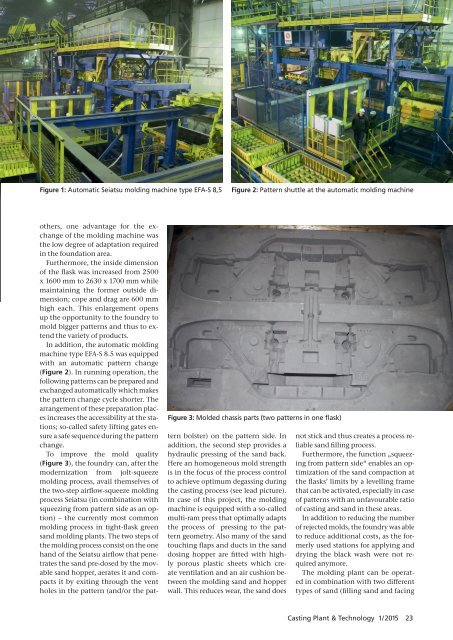
Automatic Seiatsu molding machine type EFA-S 8,5<br />
Pattern shuttle at the automatic molding machine<br />
<br />
others, one advantage for the exchange<br />
of the molding machine was<br />
the low degree of adaptation required<br />
in the foundation area.<br />
Furthermore, the inside dimension<br />
of the flask was increased from 2500<br />
x 1600 mm to 2630 x 1700 mm while<br />
maintaining the former outside dimension;<br />
cope and drag are 600 mm<br />
high each. This enlargement opens<br />
up the opportunity to the foundry to<br />
mold bigger patterns and thus to extend<br />
the variety of products.<br />
In addition, the automatic molding<br />
machine type EFA-S 8.5 was equipped<br />
with an automatic pattern change<br />
( Figure 2). In running operation, the<br />
following patterns can be prepared and<br />
exchanged automatically which makes<br />
the pattern change cycle shorter. The<br />
arrangement of these preparation places<br />
increases the accessibility at the stations;<br />
so-called safety lifting gates ensure<br />
a safe sequence during the pattern<br />
change.<br />
To improve the mold quality<br />
( ), the foundry can, after the<br />
modernization from jolt-squeeze<br />
molding process, avail themselves of<br />
the two-step airflow-squeeze molding<br />
process Seiatsu (in combination with<br />
squeezing from pattern side as an option)<br />
– the currently most common<br />
molding process in tight-flask green<br />
sand molding plants. The two steps of<br />
the molding process consist on the one<br />
hand of the Seiatsu airflow that penetrates<br />
the sand pre-dosed by the movable<br />
sand hopper, aerates it and compacts<br />
it by exiting through the vent<br />
holes in the pattern (and/or the pattern<br />
bolster) on the pattern side. In<br />
addition, the second step provides a<br />
hydraulic pressing of the sand back.<br />
Here an homogeneous mold strength<br />
is in the focus of the process control<br />
to achieve optimum degassing during<br />
the casting process (see lead picture).<br />
In case of this project, the molding<br />
machine is equipped with a so-called<br />
multi-ram press that optimally adapts<br />
the process of pressing to the pattern<br />
geometry. Also many of the sand<br />
touching flaps and ducts in the sand<br />
dosing hopper are fitted with highly<br />
porous plastic sheets which create<br />
ventilation and an air cushion between<br />
the molding sand and hopper<br />
wall. This reduces wear, the sand does<br />
not stick and thus creates a process reliable<br />
sand filling process.<br />
Furthermore, the function „squeezing<br />
from pattern side“ enables an optimization<br />
of the sand compaction at<br />
the flasks’ limits by a levelling frame<br />
that can be activated, especially in case<br />
of patterns with an unfavourable ratio<br />
of casting and sand in these areas.<br />
In addition to reducing the number<br />
of rejected molds, the foundry was able<br />
to reduce additional costs, as the formerly<br />
used stations for applying and<br />
drying the black wash were not required<br />
anymore.<br />
The molding plant can be operated<br />
in combination with two different<br />
types of sand (filling sand and facing<br />
Casting Plant & Technology 1/2<strong>01</strong>5 23