Configuration Software Flexi Soft Designer - Sick
Configuration Software Flexi Soft Designer - Sick
Configuration Software Flexi Soft Designer - Sick

You also want an ePaper? Increase the reach of your titles
YUMPU automatically turns print PDFs into web optimized ePapers that Google loves.
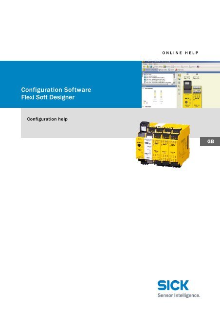
<strong>Configuration</strong> <strong><strong>Soft</strong>ware</strong><br />
<strong>Flexi</strong> <strong>Soft</strong> <strong>Designer</strong><br />
<strong>Configuration</strong> help<br />
O N L I N E H E L P<br />
GB
<strong><strong>Soft</strong>ware</strong> status described<br />
<strong><strong>Soft</strong>ware</strong> / Tool Function Status<br />
<strong>Flexi</strong> <strong>Soft</strong> <strong>Designer</strong> <strong>Configuration</strong> software V1.3.0 SP1<br />
Copyright<br />
Copyright © 2011<br />
SICK AG, Waldkirch<br />
Industrial Safety Systems<br />
Erwin-<strong>Sick</strong>-Str. 1<br />
79183 Waldkirch<br />
Germany<br />
Online Help<br />
<strong>Flexi</strong> <strong>Soft</strong> <strong>Designer</strong><br />
This work is subject to copyright. SICK AG reserves the associated rights. Duplication of this work, in whole or in<br />
part, is only permitted subject to the limits of the statutory provisions of the Copyright Act. Modification or<br />
expurgation of this work is prohibited without the express written permission of SICK AG.<br />
2 © SICK AG • Industrial Safety Systems • Germany • All rights reserved 8014174/2011-04-06<br />
Subject to change without notice
Online Help<br />
<strong>Flexi</strong> <strong>Soft</strong> <strong>Designer</strong><br />
Table of contents<br />
Table of contents<br />
1 About this document ......................................................................................................... 4<br />
2 <strong>Flexi</strong> <strong>Soft</strong> <strong>Designer</strong> – Online Help .................................................................................... 5<br />
2.1 About <strong>Flexi</strong> <strong>Soft</strong> <strong>Designer</strong> <strong>Flexi</strong> <strong>Soft</strong> <strong>Designer</strong> ..................................................... 5<br />
3 Hardware configuration .................................................................................................... 6<br />
3.1 Starting the project ............................................................................................... 6<br />
3.2 Selecting the main unit ......................................................................................... 6<br />
3.3 Selecting the expansion modules ........................................................................ 6<br />
3.4 Selecting the input elements ............................................................................... 7<br />
3.5 Selecting the actuators/displays/outputs ........................................................... 7<br />
3.6 Assigning tag names ............................................................................................. 8<br />
4 Editing the hardware configuration ................................................................................ 9<br />
4.1 Deleting and moving modules .............................................................................. 9<br />
4.2 Deleting or editing an element/discrepancy time/test signal ............................ 9<br />
5 Creating the logical process ..........................................................................................10<br />
5.1 Positioning the input elements ..........................................................................10<br />
5.2 Positioning the function blocks ..........................................................................10<br />
5.3 Positioning the outputs .......................................................................................10<br />
5.4 Simulation ...........................................................................................................11<br />
6 Connecting, transferring and verifying .........................................................................12<br />
7 Report and diagnostics ...................................................................................................13<br />
7.1 Calling and printing the report............................................................................13<br />
7.2 Calling the diagnostics ........................................................................................13<br />
8 Saving the configuration ................................................................................................14<br />
9 Device status values in the <strong>Flexi</strong> <strong>Soft</strong> system ..............................................................15<br />
10 <strong>Flexi</strong> <strong>Soft</strong> <strong>Designer</strong> Extras ..............................................................................................17<br />
10.1 Force mode ..........................................................................................................17<br />
8014174/2011-04-06 © SICK AG • Industrial Safety Systems • Germany • All rights reserved 3<br />
Subject to change without notice
About this document<br />
Chapter 1 Online Help<br />
1 About this document<br />
Function of this document<br />
Target group<br />
Information depth<br />
Important<br />
<strong>Flexi</strong> <strong>Soft</strong> <strong>Designer</strong><br />
Please read this document carefully if you do not have any<br />
previous knowledge of <strong>Flexi</strong> <strong>Soft</strong> <strong>Designer</strong>. It will simplify<br />
your work when dealing with configuration software.<br />
This document will help you when configuring your <strong>Flexi</strong><br />
<strong>Soft</strong> Station, or your <strong>Flexi</strong> Link system. Nevertheless, this<br />
document is no substitute for the <strong>Flexi</strong> <strong>Soft</strong> hardware<br />
operating instructions (document no. 8012478) or the<br />
<strong>Flexi</strong> <strong>Soft</strong> <strong>Designer</strong> operating instructions (document no.<br />
8012480). This document merely serves as a guideline<br />
and not to provide safety-relevant instructions.<br />
The target group for this document consists of people in the<br />
following roles:<br />
Roles Target group<br />
Commissioning and<br />
configuration<br />
Expert personnel, such as<br />
technicians or engineers<br />
This document takes you through the configuration of a <strong>Flexi</strong><br />
<strong>Soft</strong> Station using the <strong>Flexi</strong> <strong>Soft</strong> <strong>Designer</strong> configuration<br />
software.<br />
For information on mounting, installation, maintenance and<br />
troubleshooting, see the <strong>Flexi</strong> <strong>Soft</strong> hardware operating<br />
instructions (document no. 8012478) and the <strong>Flexi</strong> <strong>Soft</strong><br />
<strong>Designer</strong> software operating instructions (document no.<br />
8012480).<br />
You can get further information on <strong>Flexi</strong> <strong>Soft</strong> safety control<br />
and <strong>Flexi</strong> <strong>Soft</strong> <strong>Designer</strong> configuration software from SICK AG,<br />
Division Industrial Safety Systems.<br />
4 © SICK AG • Industrial Safety Systems • Germany • All rights reserved 8014174/2011-04-06<br />
Subject to change without notice
Online Help Chapter 2<br />
<strong>Flexi</strong> <strong>Soft</strong> <strong>Designer</strong><br />
<strong>Flexi</strong> <strong>Soft</strong> <strong>Designer</strong> – Online Help<br />
2 <strong>Flexi</strong> <strong>Soft</strong> <strong>Designer</strong> – Online Help<br />
Simple project configuration<br />
2.1 About <strong>Flexi</strong> <strong>Soft</strong> <strong>Designer</strong><br />
<strong>Flexi</strong> <strong>Soft</strong> <strong>Designer</strong> is a tool that allows you to configure your <strong>Flexi</strong> <strong>Soft</strong> Station. It helps you<br />
when selecting and connecting your modules and elements with simple hardware<br />
configuration and the logic editor.<br />
8014174/2011-04-06 © SICK AG • Industrial Safety Systems • Germany • All rights reserved 5<br />
Subject to change without notice
Hardware configuration<br />
Chapter 3 Online Help<br />
3 Hardware configuration<br />
3.1 Starting the project<br />
When you have started <strong>Flexi</strong> <strong>Soft</strong> <strong>Designer</strong>, select Create new project.<br />
3.2 Selecting the main unit<br />
<strong>Flexi</strong> <strong>Soft</strong> <strong>Designer</strong><br />
Now select a main unit from the Modules section. Use the mouse to drag & drop it into the<br />
configuration area or click on the desired main unit CPU0 or to CPU1 if you want to<br />
3.3 Selecting the expansion modules<br />
connect an EFI-compatible SICK<br />
sensor.<br />
After selecting the main unit, select the required expansion modules. You have three selec-<br />
tion options: gateways for integrating into the PLC, I/O modules, and relays. You can<br />
choose between 7 different<br />
gateways, 2 input and output<br />
modules, 4 relay expansions, as<br />
well as a speed monitor for<br />
standstill and drive monitoring.<br />
6 © SICK AG • Industrial Safety Systems • Germany • All rights reserved 8014174/2011-04-06<br />
Subject to change without notice
Online Help Chapter 3<br />
<strong>Flexi</strong> <strong>Soft</strong> <strong>Designer</strong><br />
Hardware configuration<br />
3.4 Selecting the input elements<br />
When you have selected all the modules, click on Elements at the bottom left.<br />
Now select your sensors/indicators/inputs from the input elements. Use the mouse to<br />
drag it to the intended module. A green mark appearing on the inputs of the expansion<br />
module indicates that these<br />
inputs can still be used. Double<br />
clicking on the required input<br />
element automatically uses the<br />
first free inputs.<br />
3.5 Selecting the actuators/displays/outputs<br />
In Elements, select Actuators/Displays/Outputs and drag the selected elements to the<br />
desired free outputs in the same way as described in 3.4.<br />
8014174/2011-04-06 © SICK AG • Industrial Safety Systems • Germany • All rights reserved 7<br />
Subject to change without notice
Hardware configuration<br />
Chapter 3 Online Help<br />
3.6 Assigning tag names<br />
<strong>Flexi</strong> <strong>Soft</strong> <strong>Designer</strong><br />
When you have selected your hardware, click on the circle icon on the left next to<br />
your CPU to define or change the tag names for the inputs and outputs. You can now<br />
assign your own names in the<br />
window that opens next.<br />
8 © SICK AG • Industrial Safety Systems • Germany • All rights reserved 8014174/2011-04-06<br />
Subject to change without notice
Online Help Chapter 4<br />
<strong>Flexi</strong> <strong>Soft</strong> <strong>Designer</strong><br />
Editing the hardware configuration<br />
4 Editing the hardware configuration<br />
4.1 Deleting and moving modules<br />
To move a module, left click on it and drag it to the desired position while holding down the<br />
left mouse button. To delete it, drag it to the trash can at the bottom left, or right click on<br />
the module and select Remove<br />
module.<br />
4.2 Deleting or editing an element/discrepancy time/test<br />
signal<br />
To delete an element, right click on the element to be deleted and select Remove. To edit<br />
an element, right click on the element and select Edit. Among other things, this is where you<br />
can configure the discrepancy<br />
time and specify whether the<br />
element is connected to test<br />
outputs. The discrepancy time is<br />
the maximum period for which<br />
both inputs can display disallowed<br />
statuses during a dual-channel<br />
evaluation, without the safety<br />
logic evaluating that status as an<br />
8014174/2011-04-06 © SICK AG • Industrial Safety Systems • Germany • All rights reserved 9<br />
Subject to change without notice<br />
error.<br />
The test signals are used to identify short circuits. Different test signal patterns are<br />
created for X1 and X2. In the event of a short circuit, only one of the signal patterns arrives<br />
at the connected inputs, therefore identifying the short circuit.
Creating the logical process<br />
Chapter 5 Online Help<br />
5 Creating the logical process<br />
5.1 Positioning the input elements<br />
5.2 Positioning the function blocks<br />
<strong>Flexi</strong> <strong>Soft</strong> <strong>Designer</strong><br />
In the Inputs window in the logic<br />
editor, select your input<br />
elements on the left and drag<br />
them to the configuration area.<br />
You can hold down Shift while<br />
left clicking to select several<br />
inputs simultaneously.<br />
When you have positioned the input elements in the configuration area, select the<br />
5.3 Positioning the outputs<br />
required function blocks on the<br />
left under Function blocks and<br />
connect them with the input<br />
elements by dragging a<br />
connection line between them.<br />
The function blocks can be<br />
edited by right clicking on them.<br />
The function block is described<br />
in the info folder in the Edit<br />
window.<br />
Now drag the output elements<br />
from the Outputs window on the<br />
left to the configuration area<br />
and connect it with the function<br />
blocks.<br />
10 © SICK AG • Industrial Safety Systems • Germany • All rights reserved 8014174/2011-04-06<br />
Subject to change without notice
Online Help Chapter 5<br />
<strong>Flexi</strong> <strong>Soft</strong> <strong>Designer</strong><br />
Creating the logical process<br />
5.4 Simulation<br />
It is possible to simulate the pro-<br />
grammed logic offline in the<br />
logic editor.<br />
Click on the Start simulation<br />
mode icon ( ) in the toolbar to<br />
activate the simulation mode.<br />
The background of the logic<br />
editor turns green and the simu-<br />
lation toolbar appears.<br />
To start a simulation of the logic, click on the green Start button for a full-speed (almost<br />
real-time) simulation. The timer indicates the time passed. The timer can be reset by<br />
clicking the blue Reset button. To stop a simulation, click on the red Stop button.<br />
8014174/2011-04-06 © SICK AG • Industrial Safety Systems • Germany • All rights reserved 11<br />
Subject to change without notice
Connecting, transferring and<br />
verifying<br />
Chapter 6 Online Help<br />
6 Connecting, transferring and verifying<br />
<strong>Flexi</strong> <strong>Soft</strong> <strong>Designer</strong><br />
When you have configured the hardware and the logic in <strong>Flexi</strong> <strong>Soft</strong> <strong>Designer</strong> and checked it<br />
for correctness, click on the Connect button to establish a<br />
connection to your <strong>Flexi</strong> <strong>Soft</strong> system. You can then transfer your project to the <strong>Flexi</strong> <strong>Soft</strong><br />
system and verify it. Transfer the configuration by clicking on the Transfer button.<br />
Enter SICKSAFE as the password in the window that appears. Then click on<br />
Log in. As long as the <strong>Flexi</strong> <strong>Soft</strong> system is not verified, the application will not start auto-<br />
matically when the power is switched on.<br />
To do this, click on the Receive and Compare <strong>Configuration</strong> icon.<br />
The system opens the Upload and verify result window. If the configuration displayed here<br />
is the one you expected, select Yes for Set device to verified? near the bottom of the<br />
screen. The system is now verified.<br />
As soon a project has been verified by an authorized customer, the maintenance techni-<br />
cian can download the project with his/her password. (For more information on this<br />
subject, see the <strong>Flexi</strong> <strong>Soft</strong> <strong>Designer</strong> operating instructions 8012480)<br />
12 © SICK AG • Industrial Safety Systems • Germany • All rights reserved 8014174/2011-04-06<br />
Subject to change without notice
Online Help Chapter 7<br />
<strong>Flexi</strong> <strong>Soft</strong> <strong>Designer</strong><br />
Report and diagnostics<br />
7 Report and diagnostics<br />
The standard Report view provides a full report for the current project and all configuration<br />
settings, including logic programming and wiring. You can define the scope of the report<br />
for yourself. And you can also enter additional notes on your project.<br />
7.1 Calling and printing the report<br />
To call the report, press the Report button. You can then select the scope of the report<br />
7.2 Calling the diagnostics<br />
from the list on the left. Press<br />
the Refresh report button. The<br />
report is generated and<br />
displayed on the right.<br />
The top half of the Diagnostics window has a list all the messages, information, warnings<br />
and error messages in your system. Clicking on the entries in the list displays details on<br />
the selected message in the<br />
lower half of the window.<br />
Click on the Diagnostics button in the menu bar to switch to the standard Diagnostics<br />
view. The toolbar contains the following commands:<br />
Click on Refresh to export the current list of messages from the system.<br />
8014174/2011-04-06 © SICK AG • Industrial Safety Systems • Germany • All rights reserved 13<br />
Subject to change without notice
Saving the configuration<br />
Chapter 8 Online Help<br />
8 Saving the configuration<br />
<strong>Flexi</strong> <strong>Soft</strong> <strong>Designer</strong><br />
At the end of your project, you can save it. To do this, click on the Project button and<br />
select Save.<br />
14 © SICK AG • Industrial Safety Systems • Germany • All rights reserved 8014174/2011-04-06<br />
Subject to change without notice
Online Help Chapter 9<br />
<strong>Flexi</strong> <strong>Soft</strong> <strong>Designer</strong><br />
Device status values in the <strong>Flexi</strong> <strong>Soft</strong><br />
system<br />
9 Device status values in the <strong>Flexi</strong> <strong>Soft</strong> system<br />
The <strong>Flexi</strong> <strong>Soft</strong> system recognizes different device status values during operation. Some<br />
device status values require intervention by the user. The following table provides a<br />
summary of typical device status values for the <strong>Flexi</strong> <strong>Soft</strong> system.<br />
CPU<br />
MS LED<br />
� Red (1 Hz)<br />
MS LED<br />
� Red (1 Hz)<br />
MS LED<br />
� Green<br />
(1 Hz)<br />
CV LED<br />
� Yellow<br />
(1 Hz)<br />
MS LED<br />
� Green<br />
(1 Hz)<br />
CV LED<br />
� Yellow<br />
MS LED<br />
� Green<br />
MS LED<br />
� Green<br />
Expansion<br />
modules (EM)<br />
MS LED for all EMs<br />
� Red/Green<br />
(1 Hz)<br />
with firmware V1.xx<br />
� Red (1 Hz)<br />
with firmware V2.xx<br />
MS LED for an EM<br />
� Red/Green<br />
(1 Hz) with firmware<br />
V1.xx<br />
MS LED for an EM<br />
� Red/Green<br />
(1 Hz) with firmware<br />
V2.xx<br />
MS LED<br />
� Green (1 Hz)<br />
MS LED<br />
� Green (1 Hz)<br />
MS LED<br />
� Green<br />
MS LED for an EM<br />
� Red (1 Hz)<br />
with firmware V1.xx<br />
MS LED for an EM<br />
� Red/Green<br />
(1 Hz)<br />
with firmware ≥ V2.xx<br />
Q1 … Q4<br />
� Green (1 Hz)<br />
Possible reason Actions<br />
Expansion module missing Add the missing modules as specified<br />
Module with flashing LED is wrong<br />
type or wrong version<br />
Too many EMs connected<br />
System is idle,<br />
configuration not yet verified<br />
System is idle,<br />
<strong>Configuration</strong> verified<br />
System running, no error detected ---<br />
No power supply for expansion<br />
module<br />
by the configuration<br />
Change the modules so that they<br />
match the configuration<br />
Start application in <strong>Flexi</strong> <strong>Soft</strong> <strong>Designer</strong><br />
Start application in <strong>Flexi</strong> <strong>Soft</strong> <strong>Designer</strong><br />
Check the power supply<br />
A1 = 24 V / A2 = 0 V<br />
When the reason for the error has<br />
been removed, the error disappears<br />
automatically after around 8 seconds.<br />
8014174/2011-04-06 © SICK AG • Industrial Safety Systems • Germany • All rights reserved 15<br />
Subject to change without notice
Device status values in the<br />
<strong>Flexi</strong> <strong>Soft</strong> system<br />
Chapter 9 Online Help<br />
MS LED<br />
� Green<br />
MS LED<br />
� Green<br />
MS LED<br />
� Green<br />
MS LED<br />
� Red<br />
MS LED<br />
� Red<br />
MS LED<br />
� Red (2 Hz)<br />
MS LED for an EM<br />
� Red (1 Hz)<br />
with firmware V1.xx<br />
MS LED for an EM<br />
� Red/Green<br />
(1 Hz)<br />
with firmware ≥ V2.xx<br />
Q1,Q2,Q3 or Q4<br />
� Green (1 Hz)<br />
MS LED for an EM<br />
� Red (1 Hz)<br />
with firmware V1.xx<br />
MS LED for an EM<br />
� Red/Green<br />
(1 Hz)<br />
with firmware ≥ V2.xx<br />
I1, I2, I3, I4, I5, I6, I7<br />
or I8<br />
� Green (1 Hz)<br />
MS LED for an EM<br />
� Red (1 Hz)<br />
with firmware V1.xx<br />
MS LED for an EM<br />
� Red/Green<br />
(1 Hz)<br />
with firmware ≥ V2.xx<br />
I1 + I2 or I3 + I4 or I5<br />
+ I6<br />
or I7 + I8<br />
� Green (1 Hz)<br />
MS LED<br />
� Red<br />
MS LED<br />
� Red (2 Hz)<br />
MS LED<br />
� Red<br />
Short circuit in the output wiring Check the output wiring.<br />
Short circuit at 24 V in the wiring<br />
for tested sensors.<br />
• Defective safety mat<br />
• Defective testable<br />
<strong>Flexi</strong> <strong>Soft</strong> <strong>Designer</strong><br />
To reset the error, use the logic to<br />
deactivate the affected outputs or<br />
reset the CPU module by disconnect-<br />
ing it from the power source and then<br />
reconnecting it.<br />
16 © SICK AG • Industrial Safety Systems • Germany • All rights reserved 8014174/2011-04-06<br />
Subject to change without notice<br />
sensor<br />
• Connection between<br />
cable and safety mat<br />
interrupted at I1, I2, …<br />
or I8<br />
• Short circuit at 24 V in<br />
the wiring for tactile<br />
switches<br />
Discrepancy error for dual-channel<br />
inputs when the LEDs flash for the<br />
input pair: I1/I2, I3/I4, I5/I6, I7/I8<br />
No power supply 0 V for XTIO<br />
Internal error in the EM<br />
Internal error in the main unit<br />
Internal error in the expansion<br />
module<br />
Internal error in the main unit or in<br />
the system<br />
Check the input wiring.<br />
Replace the tested sensor.<br />
To reset the error, use the logic to<br />
deactivate the affected inputs or reset<br />
the CPU module by disconnecting it<br />
from the power source and then<br />
reconnecting it.<br />
Check the wiring for the affected input.<br />
Check the connected sensor to ensure<br />
that both inputs switch within the<br />
discrepancy time.<br />
To reset the error, deactivate the<br />
affected inputs or restart the CPU.<br />
Check the power supply for the EM (0 V)<br />
Restart the system. If the error<br />
persists, swap the modules<br />
Check the installation. Restart the<br />
system. If the error persists, swap the<br />
module with the flashing LED<br />
Check the installation. Restart the<br />
system. If the error persists, swap the<br />
module with the flashing LED
Online Help Chapter 10<br />
<strong>Flexi</strong> <strong>Soft</strong> <strong>Designer</strong><br />
<strong>Flexi</strong> <strong>Soft</strong> <strong>Designer</strong> Extras<br />
10 <strong>Flexi</strong> <strong>Soft</strong> <strong>Designer</strong> Extras<br />
10.1 Force mode<br />
In force mode, you can use the software to set the inputs for logic function blocks for a <strong>Flexi</strong><br />
<strong>Soft</strong> system to High or Low while the system is online, regardless of their actual status. The<br />
logic then behaves exactly as if the affected inputs actually have the corresponding status.<br />
Click on Connect to connect to your <strong>Flexi</strong> <strong>Soft</strong> system. Then click in the Hardware con-<br />
figuration view on the Start application button.<br />
Switch to the Logic editor and click on the Start Force Mode button ( ). The system<br />
opens a dialog in which you can enter the time after which force mode is quitted automa-<br />
tically if no further actions are triggered. Select the required time from the selection list<br />
and click on OK. Force mode is started and the background color of the logic editor<br />
changes to red. Left click on the input to change its status.<br />
8014174/2011-04-06 © SICK AG • Industrial Safety Systems • Germany • All rights reserved 17<br />
Subject to change without notice
8014174/2011-04-06<br />
Australia<br />
Phone +61 3 9497 4100<br />
1800 33 48 02 – toll-free<br />
E-mail sales@sick.com.au<br />
Belgium/Luxembourg<br />
Belgium/Luxembourg<br />
Phone +32 (0)2 466 55 66<br />
E-mail info@sick.be<br />
Brasil<br />
Brasil<br />
Phone +55 11 3215 -4900<br />
E-mail sac@sick.com.br<br />
Ceská Ceská Republika<br />
Republika<br />
Phone +420 2 57 91 18 50<br />
E-mail sick@sick.cz<br />
China<br />
China<br />
Phone +852-2763 6966<br />
E-mail ghk@sick.com.hk<br />
Danmark<br />
Danmark<br />
Phone +45 45 82 64 00<br />
E-mail sick@sick.dk<br />
Germany<br />
Germany<br />
Phone +49,2115301 -301<br />
E-mail kundenservice@sick.de<br />
España España<br />
España<br />
Phone +34 93 480 31 00<br />
E-mail info@sick.es<br />
France<br />
France<br />
Phone +33 1 64 62 35 00<br />
E-mail info@sick.fr<br />
Great Great Britain<br />
Britain<br />
Phone +44 (0)1727 831121<br />
E-mail info@sick.co.uk<br />
India<br />
India<br />
Phone +91 -22 -4033 8333<br />
E-mail info@sick-india.com<br />
Israel<br />
Israel<br />
Phone +972-4-999-0590<br />
E-mail info@sick-sensors.com<br />
Italia Italia<br />
Italia<br />
Phone +39 02 27 43 41<br />
E-mail info@sick.it<br />
Japan<br />
Japan<br />
Phone +81 (0)3 3358 1341<br />
E-mail support@sick.jp<br />
Nederlands<br />
Nederlands<br />
Phone +31 (0)30,229 25 44<br />
E-mail info@sick.nl<br />
Norge Norge<br />
Norge<br />
Phone +47 67 81 50 00<br />
E-mail austefjord@sick.no<br />
SICK AG | Waldkirch | Germany | www.sick.com<br />
Austria<br />
Austria<br />
Phone +43 (0)22 36 62 28 8-0<br />
E-mail: office@sick.at<br />
Polska<br />
Polska<br />
Phone +48 22,837 40 50<br />
E-mail info@sick.pl<br />
Republic Republic of of Korea<br />
Korea<br />
Phone +82-2 786 6321/4<br />
E-mail info@sickkorea.net<br />
Republika Republika Slovenija<br />
Slovenija<br />
Phone +386 (0)1 -47 69,990<br />
E-mail office@sick.si<br />
România<br />
România<br />
Phone +40 356 171 120<br />
E-mail office@sick.ro<br />
Russia<br />
Russia<br />
Phone +7 495 775 05 34<br />
E-mail info@sick-automation.ru<br />
Switzerland<br />
Switzerland<br />
Phone +41 41,619 29 39<br />
E-mail: contact@sick.ch<br />
Singapore<br />
Singapore<br />
Phone +656744 3732<br />
E-mail admin@sicksgp.com.sg<br />
South South South Africa<br />
Africa<br />
Phone +2711,472 3737<br />
E-mail info@sickautomation.co.za<br />
Suomi<br />
Suomi<br />
Phone +358 -9 -25 15,800<br />
E-mail sick@sick.fi<br />
Sverige<br />
Sverige<br />
Phone +46 10,110 10 00<br />
E-mail info@sick.se<br />
Taiwan<br />
Taiwan<br />
Phone +886 2 2375 -6288<br />
E-mail sales@sick.com.tw<br />
Türkiye<br />
Türkiye<br />
Phone +90 216 528 50 00<br />
E-mail info@sick.com.tr<br />
United United Arab Arab Emirates<br />
Emirates<br />
Phone +971 4 8865 878<br />
E-mail info@sick.ae<br />
USA/Canada/México<br />
USA/Canada/México<br />
Phone +1 (952)941 -6780<br />
1 800-325-7425 – toll-free<br />
E-mail info@sickusa.com<br />
More representatives and agencies<br />
at www.sick.com<br />
www.sick.com