Configuration Software Flexi Soft Designer - Sick
Configuration Software Flexi Soft Designer - Sick
Configuration Software Flexi Soft Designer - Sick

Create successful ePaper yourself
Turn your PDF publications into a flip-book with our unique Google optimized e-Paper software.
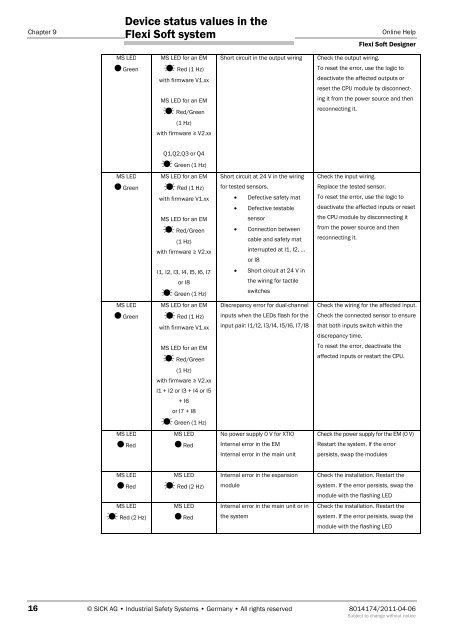
Device status values in the<br />
<strong>Flexi</strong> <strong>Soft</strong> system<br />
Chapter 9 Online Help<br />
MS LED<br />
� Green<br />
MS LED<br />
� Green<br />
MS LED<br />
� Green<br />
MS LED<br />
� Red<br />
MS LED<br />
� Red<br />
MS LED<br />
� Red (2 Hz)<br />
MS LED for an EM<br />
� Red (1 Hz)<br />
with firmware V1.xx<br />
MS LED for an EM<br />
� Red/Green<br />
(1 Hz)<br />
with firmware ≥ V2.xx<br />
Q1,Q2,Q3 or Q4<br />
� Green (1 Hz)<br />
MS LED for an EM<br />
� Red (1 Hz)<br />
with firmware V1.xx<br />
MS LED for an EM<br />
� Red/Green<br />
(1 Hz)<br />
with firmware ≥ V2.xx<br />
I1, I2, I3, I4, I5, I6, I7<br />
or I8<br />
� Green (1 Hz)<br />
MS LED for an EM<br />
� Red (1 Hz)<br />
with firmware V1.xx<br />
MS LED for an EM<br />
� Red/Green<br />
(1 Hz)<br />
with firmware ≥ V2.xx<br />
I1 + I2 or I3 + I4 or I5<br />
+ I6<br />
or I7 + I8<br />
� Green (1 Hz)<br />
MS LED<br />
� Red<br />
MS LED<br />
� Red (2 Hz)<br />
MS LED<br />
� Red<br />
Short circuit in the output wiring Check the output wiring.<br />
Short circuit at 24 V in the wiring<br />
for tested sensors.<br />
• Defective safety mat<br />
• Defective testable<br />
<strong>Flexi</strong> <strong>Soft</strong> <strong>Designer</strong><br />
To reset the error, use the logic to<br />
deactivate the affected outputs or<br />
reset the CPU module by disconnect-<br />
ing it from the power source and then<br />
reconnecting it.<br />
16 © SICK AG • Industrial Safety Systems • Germany • All rights reserved 8014174/2011-04-06<br />
Subject to change without notice<br />
sensor<br />
• Connection between<br />
cable and safety mat<br />
interrupted at I1, I2, …<br />
or I8<br />
• Short circuit at 24 V in<br />
the wiring for tactile<br />
switches<br />
Discrepancy error for dual-channel<br />
inputs when the LEDs flash for the<br />
input pair: I1/I2, I3/I4, I5/I6, I7/I8<br />
No power supply 0 V for XTIO<br />
Internal error in the EM<br />
Internal error in the main unit<br />
Internal error in the expansion<br />
module<br />
Internal error in the main unit or in<br />
the system<br />
Check the input wiring.<br />
Replace the tested sensor.<br />
To reset the error, use the logic to<br />
deactivate the affected inputs or reset<br />
the CPU module by disconnecting it<br />
from the power source and then<br />
reconnecting it.<br />
Check the wiring for the affected input.<br />
Check the connected sensor to ensure<br />
that both inputs switch within the<br />
discrepancy time.<br />
To reset the error, deactivate the<br />
affected inputs or restart the CPU.<br />
Check the power supply for the EM (0 V)<br />
Restart the system. If the error<br />
persists, swap the modules<br />
Check the installation. Restart the<br />
system. If the error persists, swap the<br />
module with the flashing LED<br />
Check the installation. Restart the<br />
system. If the error persists, swap the<br />
module with the flashing LED